Abstract
Al/Mg dissimilar welds were successfully fabricated by refill friction stir spot welding using a grooved sleeve tool. Influences of sleeve penetration depth and rotational speed on the weld formation and mechanical performance were systematically evaluated in terms of welding parameter optimization, interfacial bonding mechanism, hardness distribution and welded joint strength. The results indicated that the success of joining Al alloy to Mg alloy significantly depends on tool sleeve penetration depth. The interfacial bonding mechanism compromised both metallurgical bonding and mechanical inter-locking. Intermetallic compound layers of Al3Mg2 and Al12Mg17 were formed at the Al/Mg interface. The thickness of the intermetallic compound (IMC) layer at the weld center increased from 20–30 μm to 40 μm when the rotational speed increased from 1000 to 2000 rpm. The minimum hardness was 80 HV in Al 7075 and 52 HV in ZEK 100; both were measured in the heat affected zone. The welded joint lap shear strength decreased, and the scatter increased with the increasing of rotation speed, whose maximum was 3.6 kN when the rotational speed was 1000 rpm. In addition, the failure mechanism was determined by tool rotational speed, and found to be interfacial failure under a rotational speed of 1000 rpm and nugget pullout under a rotational speed of 2000 rpm.
1. Introduction
With the purpose of reducing structural weight and providing environmental protection, lightweight materials such as Al and Mg alloys have been used to replace conventional steel structures in the automotive, aerospace, high speed rail, and shipbuilding industries [1]. The application of hybrid structures has gained increasing attention because it is the best option to combine the advantages of the dissimilar materials [2]. However, it is extremely challenging to fabricate reliable Al/Mg dissimilar welds due to the formation of brittle intermetallic compounds (IMCs). Currently, several approaches have been adopted to join Al/Mg dissimilar welds, including: (i) mechanical joining technology such as self-pierce riveting [3]; (ii) fusion welding such as laser welding [4,5,6], cold metal transfer welding [7], TIG welding [8], and resistance spot welding [9]; and (iii) solid-state joining technology such as ultrasonic spot welding [10,11,12], friction stir welding (FSW) [13,14,15,16], and conventional friction stir spot welding (FSSW) [16,17].
Self-pierce riveting can result in a poor working environment, low production efficiency, and high cost. By comparison, fusion welding technologies can cause bulk IMC formation and defects such as porosity and cracking [5,6,7,8,9]. It should be noted that it is necessary to form an IMC layer to promote metallurgical bonding at the Al/Mg interface. Compared to these joining methods, solid-state welding technologies have significant advantages because they suppress temperature rise and therefore can avoid bulk IMCs and defect formation, which commonly occur in fusion welding, although IMC formation remains inevitable during the solid-state welding process. The above-mentioned conventional FSSW has been exploited based on the basic fundaments of linear FSW [18]. As a solid-state joining technology, conventional FSSW has the same merits as FSW [19]. However, an undesirable keyhole depression is left in the weld center after pin tool retraction, which results in stress concentration and significantly decreases the weld strength [20].
To overcome the disadvantages in conventional FSSW, pinless FSSW and short traverse FSW variants, such as swept FSW, stitch FSW and swing FSW, have been explored to improve the effective bonded area and weld integrity [21]. Nevertheless, pinless FSSW is not suitable to join relatively thick sheet material (≥1.0 mm) [22], and short traverse FSW variant processes are relatively complex for mass production. Thus, Schilling and Dos Santos developed refill FSSW based on the retractable tool used in FSW at Helmholtz-Zentrum Geesthacht, Germany, in 1999 [23]. As shown in Figure 1, the refill FSSW process was performed using a tool comprising three parts: a stationary clamping ring, an outer sleeve, and an inner pin. The tool’s detailed processes were discussed in previous research [24]. The role of the clamping ring is to hold the workpiece firmly and avoid material loss during the welding process. The sleeve and pin can rotate in the same direction and accelerate via their connection to one motor, and move up and down independently via the use of separate actuators [25].
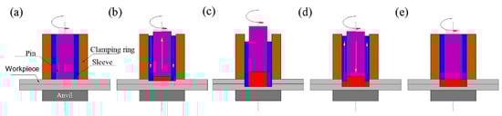
Figure 1.
Schematic illustration of refill FSSW: (a) surface preheating to soften workpiece material, (b) sleeve penetration, (c) stirring after penetration, (d) sleeve retracts, and (e) surface dwell to flatten weld surface.
Refill FSSW has been successfully applied to join high strength Al alloy [26,27] and Mg alloy [28,29], and dissimilar welds such as Mg/steel [29,30], Al/steel [31,32,33], and Al/Mg [34,35,36,37,38,39]. Wang et al. reported that Al–Zn coating was beneficial to suppress the formation of the faster growing Al3Mg2 phase at the Al/Mg interface, and Al–Si coatings led to a significant reduction in the IMC reaction layer thickness, which further increased welded joint lap shear strength [36,38]. Suhuddin et al. found fine equiaxed grains of Al12Mg17 was formed in the weld center [37], and distribution of IMCs introduced by material flow affected welded joint lap shear strength [35]. Dong et al. demonstrated that the maximum temperature was 425 °C during the refill FSSW of Al/Mg, and the weld strength decreased with the increase in the IMC thickness [34].
Based on the open literature, a 9.0 mm diameter threaded sleeve is commonly used to facilitate material flow and chip removal. It is relatively difficult to fabricate a defect-free weld via welding parameter optimization using a threaded sleeve. Recently, Shen et al. found that a grooved sleeve can significantly increase plastic deformation, and created a mechanical inter-locking joining mechanism in Al 7075 similar and Al 6022/Al 7075 dissimilar welds [40,41]. More than 95% of this plastic deformation energy is dissipated as heat and conducts to the surroundings, and only <5% of the energy is stored in the microstructure, such as crystal defects and grain boundaries [42]. Therefore, it is of interest to apply the grooved sleeve tool to joining the Al/Mg dissimilar weld. Thus, the present article discusses the interfacial bonding and mechanical performance of Al/Mg dissimilar welds using a grooved sleeve.
2. Materials and Methods
The base materials chosen for this study were 0.9 mm thick Al 7075-T6 and 1.5 mm thick ZEK100-O Mg alloy, and were provided by Ford Motor Co and Magnesium Elektron, respectively. The base materials’ measured chemical compositions are listed in Table 1. Mechanical properties of the as-received substrate materials are listed in Table 2. Al 7075 is characterized by high strength and ZEK 100 Mg alloy has excellent formability at room temperature. The spot welds were fabricated using a 25 mm × 100 mm coupon with a 25 mm × 25 mm overlap area according to the American Welding Society (AWS) standard D 17.2/D17.2M [43]. It should be noted that no surface treatment was performed before the welding process; the Al alloy was placed on top of Mg alloy sheet, and the weld was fabricated in the center of the overlapped area.

Table 1.
The measured chemical composition of substrate materials (wt%).
Table 2.
Mechanical properties of substrate materials.
The welding process was carried out using a Harms & Wende RPS100 refill FSSW machine (Coldwater Machine Co., Coldwater, OH, USA). The welding tool used in this investigation was machined from H13 steel, and the diameter of the clamping ring, sleeve, and pin were 14.5, 9.0, and 6.4 mm, respectively. Three equally distributed grooves were fabricated on the sleeve bottom, whose detailed geometries were provided elsewhere [40,41]. The tool rotational speed was 1000, 1500, and 1800 rpm, which was constant during the entire welding period once it was selected. The sleeve penetration depth was 0.6, 0.9, and 1.2 mm, respectively. The welding time was 4 s, where the dwell time was 2 s, and the penetration and retraction times were 1 s regardless of the penetration depth.
After the welding operation, the weld was sectioned through the weld center by water jet cutting. The weld macro/microstructure was observed using an OLYMPUS NTB 3558 optical microscope after the weld cross-section was prepared using a standard metallographic technique and chemically etched by Keller’s reagent (2 mL HF + 3 mL HCl + 5 mL HNO3 + 190 mL water). The IMC distribution was identified on the as-polished sample using a JEOL JSM-6460 scanning electron microscope (SEM) system. All of the chemical compositions measured by EDX spectroscopy were reported as wt%. The hardness was measured using a 432SVD Vickers micro-hardness tester (Buehler Ltd., Lake Bluff, IL, USA), in the mid-thickness of top and bottom sheets using a holding time of 10 s and a force of 50 g. The overlap shear tests were performed using a CHANGCHUN CSS-44100 electronic universal testing machine (Sinotest Equipment Co., Ltd., Changchun, China) with a displacement rate of 10 mm/min. All of the overlap shear welded joint strengths reported are the average of at least three individual specimens.
3. Results and Discussion
3.1. Welding Parameter Optimization
To achieve a stable joining process and avoid the effect of repetitive preheating generated from friction between each component of the welding tool, an interval time of 5 minutes was applied during the welding of each spot weld. A preliminary operation was conducted to confirm the effect of the tool sleeve penetration depth on the weld formation. Similar to the joining of Al alloy to zinc coated steel by refill FSSW [31], the weld separated through the Al/Mg interface or the nugget was pulled out immediately after the joining process, regardless of the rotational speed, when the tool sleeve penetration depth was 0.6 and 1.2 mm (<66.7% or >133.3% of the top Al alloy), respectively. Therefore, the penetration depth was set to be 0.9 mm in the following investigation.
As shown in Figure 2a, metallurgical bonding was not achieved at the Al/Mg interface when the weld was fabricated using a penetration depth of 0.6 mm. It can be observed that the oxide layer cladded on the workpiece surface was not broken up into fine particles, and thus dispersed into the matrix due to insufficient heat input, although plastic deformation with an annular flute pattern was formed due to sleeve penetration. It should be noted that the plastic deformation thickness was much thicker than the sleeve penetration depth, which was equal to sleeve penetration depth when the welds were fabricated using a threaded sleeve tool [26,27,28,29].
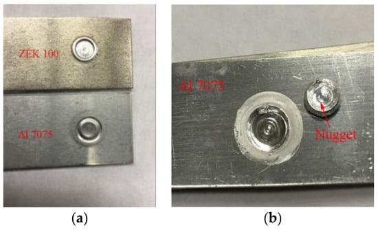
Figure 2.
The failed welds directly after welding operation: (a) interfacial failure and (b) nugget.
It can be observed from Figure 2b that the nugget was completely pulled out by the welding tool when the weld was fabricated using a sleeve penetration depth of 1.2 mm; the tool’s diameter corresponded to that of the sleeve. Failure of the joining can be attributed to excessive heating and bulk brittle IMC formation. In addition, it is notable that the top Al 7075 sheet was still joined to the bottom ZEK100 sheet, and the welding area was shiny, which indicated that superplasticity of ZEK 100 Mg alloy can be achieved at elevated temperatures.
3.2. Microstructure and Interfacial Bonding
A typical cross-section and microstructure of the weld fabricated using a rotational speed of 1000 rpm is presented in Figure 3 to investigate the localized microstructure. The top Al 7075 microstructure has been extensively investigated in previous research [26,27,36]; thus, the present study only focused on interfacial bonding. As indicated in Figure 3a, defect-free Al/Mg dissimilar welds can be fabricated using a grooved sleeve tool, and no defects such as bonding ligament, incomplete refill, or lack of mixing can be observed in the weld. These defects are commonly formed in the welds fabricated using a threaded tool due to insufficient material flow [24,25,26]. It should be noted that the dark area between the top and lower sheets was not due to cracking or other defects, which resulted from removal of interfacial material during the polishing. In addition, the top Al 7075 sheet material penetrated into the bottom ZEK100 sheet material underneath the sleeve, and thus the ZEK100 sheet material was displaced upward, which created a mechanical inter-locking joining mechanism around the weld boundary.
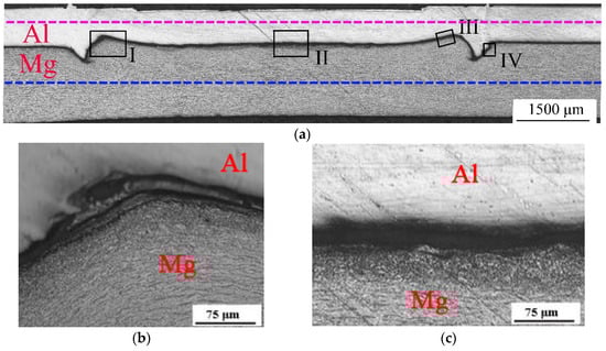
Figure 3.
Microstructure of the weld fabricated using a rotational speed of 1000 rpm: (a) overall cross-section, (b) magnified view in region of I and (c) region II.
Magnified views of regions I and II in Figure 3a are shown in Figure 3b,c, respectively. It can be clearly observed that a continuous IMC layer with non-uniform thickness was formed on the whole faying surface due to the metallurgical reaction between Al and Mg sheet materials. Compared to the dynamic recrystallization layer, which was equal to the penetration depth when a threaded sleeve was applied, a layer of bottom Mg alloy sheet material underwent dynamic recrystallization due to severe plastic deformation at the elevated temperature imposed by the grooved tool (see Figure 3b,c). This dynamic recrystallization zone is commonly referred to as the stir zone (SZ). The material flow pattern can be identified through the grain bending in Figure 3b, where the material underwent moderate plastic deformation and temperature, and thus formed a thermo-mechanically affected zone (TMAZ). The material located between the TMAZ and the base material (BM) only experienced a thermal cycle and formed a heat affected zone (HAZ). In addition, the IMC layer was thicker at the weld boundary than in the weld center because considerably more frictional heat was generated due to higher linear velocity at the weld boundary.
SEM images in the locations of II-IV in Figure 3a are shown in Figure 4a–c to investigate the Al/Mg interfacial bonding in detail. The chemical composition distributions in regions II, III, and IV are indicated in Figure 5a–c to identify IMCs, respectively. As shown in Figure 4a, the IMC thickness ranged from 20 to 30 μm at the weld center. The chemical composition in the location of E in Figure 4a was 60.32%Al and 39.68%Mg (see Figure 5a), which is consistent with Al3Mg2 according to the Al–Mg phase diagram. However, the IMC thickness exceeded 40 μm at the weld center (see Figure 6a), when the weld was fabricated using a rotational speed of 2000 rpm, because more heat was generated from tool rotation (torque). The chemical composition in the location of B in Figure 6a was 52.19%Al and 47.09%Mg, which was supposed to be Al3Mg2 (see Table 3). In addition, cracking can be observed at the IMC layer, which probably occurred during the sample reparation or can be attributed to the residual stress during the cooling period.
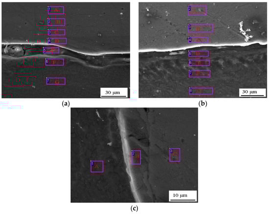
Figure 4.
SEM image in the region of (a) II, (b) III, (c) IV in Figure 3a.
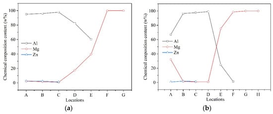
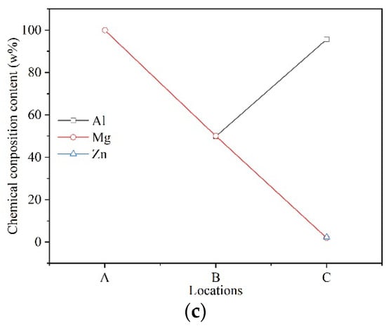
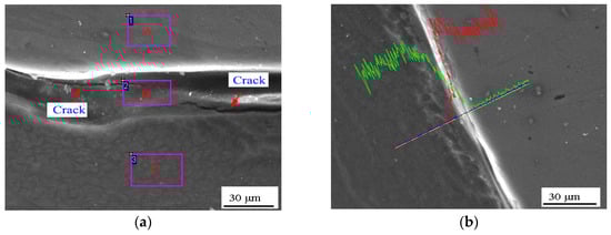
Figure 6.
IMC layer at (a) weld center and (b) boundary of the weld fabricated using a rotational speed of 1500 rpm.
Table 3.
EDX quantification results (wt%) indicated in Figure 6a.
It is interesting to observe from Figure 4b that the IMC layer was relatively thin at the weld boundary (ranging from 10 to 20 μm). The chemical composition in the location of D in Figure 4b was 24.74%Al and 75.25%Mg (see Figure 5b), which is consistent with Al12Mg17 with a small amount of Mg in solution. Furthermore, metallurgical bonding was achieved at the weld external periphery, where the IMC layer thickness ranged from 5 to 10 μm (see Figure 4c). The chemical composition in the location of B was 49.9%Al and 50.1%Mg, which is consistent with Al3Mg2. The thickness of the IMC layer located at the weld boundary increased to approximately 10 μm (see Figure 6b), when the weld was fabricated using a rotational speed of 2000 rpm.
Overall, the IMC layer was considerably thicker in the weld center because the heat input during FSSW remained at a single spot compared to that of linear FSW [44], and the heat can be easily dissipated into the surrounding cold substrate materials. Furthermore, Rosakis et al. reported that more than 95% of the plastic deformation energy dissipated as heat [42], and Awang et al. found that only 3.14% of the heat was generated from plastic deformation during FSSW of Al 6061 alloy [45]. These findings readily explain the thin IMC layer formed at the weld boundary, although the grooved sleeve produced more plastic deformation compared to the threaded sleeve.
3.3. Mechanical Properties
The hardness distribution was conducted along the mid-thickness of the top Al 7075 and bottom ZEK100 Mg alloy sheet of the weld fabricated using a rotational speed of 1500 rpm. The measurement locations are marked by red and blue chain-dotted lines in Figure 3a, respectively. As a precipitation-hardened alloy, the hardness of Al 7075 sheet materials is mainly governed by the state and distribution of the precipitates rather than grain size [46]. As shown in Figure 7, the top Al 7075 material hardness was significantly softened in the welded zone, which can be attributed to coarsening or dissolution of Mg2Zn and Al2CuMg phase precipitates due to the thermal cycle imposed by the welding tool. It should be noted that the hardness slightly increased to approximately 100 HV in the SZ because the hardness was measured after one week of natural ageing, which can cause reprecipitation of Mg (Zn2, AICu) and Mg32(Al, Zn)49 particles. The minimum hardness was 80 HV in the HAZ, where the material only experienced frictional heat and caused coarsening of the precipitates.
Figure 7.
Hardness distribution in the mid-thickness of the Al and Mg sheet of the weld fabricated using a rotational speed of 1500 rpm.
Regarding ZEK100 Mg alloy, the peak hardness value was measured in the SZ, which is higher than that of the substrate material due to the presence of fine grain microstructure according to the Hall–Petch relationship. A hardness reduction was measured in HAZ (approximately 52 HV), which can be attributed to coarsening of grain size [34]. It is notable that the HAZ was relatively wide in both the top Al alloy and bottom Mg alloy sheet, and was approximately 10 mm.
The relationship between rotational speed and welded joint lap shear strength is presented in Figure 8. It can be observed that the welded joint lap shear strength decreased, and the scatter became smaller with the rotational speed. A maximum value of 3.6 kN was achieved when the weld was fabricated using a rotational speed of 1000 rpm because a mechanical inter-locking joining mechanism was created and the IMC layer was relatively thinner when the weld was manufactured under a lower heat input welding condition (see Figure 3 and Figure 4). The welded joint lap shear strength decreased to a minimum level of 1.82 kN when the weld was fabricated using a rotational speed of 2000 rpm, which can be attributed to the thick IMC layer formed at the Al/Mg interface (see Figure 6a).
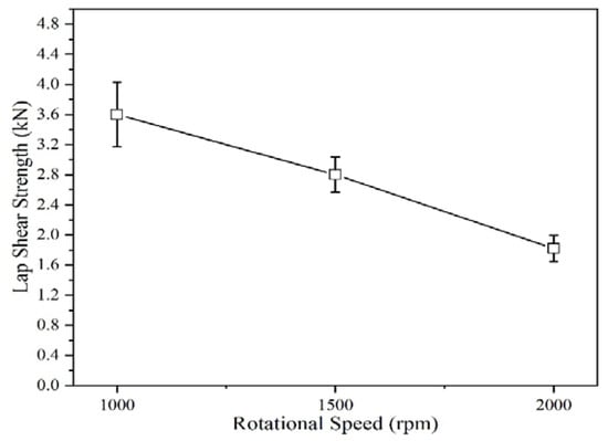
Figure 8.
Relationship between rotational speed and lap shear strength of the welds.
The failure mode of the welds tested under lap shear loading is shown in Figure 9, which compromised nugget pullout and interfacial failure. As shown in Figure 9a, the nugget was pulled out from the bottom ZEK100 Mg alloy sheet around the weld boundary when the weld was fabricated using a rotational speed of 1000 rpm, and the nugget remained on the top Al 7075 sheet. As shown in Figure 3a, the top Al 7075 sheet material penetrated into the bottom Mg sheet, which significantly reduced the effective thickness of Mg ally. Furthermore, the IMC layer was formed at the weld boundary, and thus the crack initiated at the weld boundary and then propagated along the Al/Mg interface, and ultimately failed on the bottom ZEK100 Mg alloy sheet. As shown in Figure 9b, the weld failure mode was interfacial failure when the weld was manufactured using a rotational speed of 2000 rpm because the IMC layer was relatively thick at both the weld center and boundary (see Figure 6).
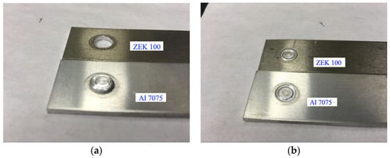
Figure 9.
Failure mode of the Al/Mg dissimilar welds under lap shear loadings: (a) nugget pullout and (b) interfacial failure.
4. Conclusions
This paper is the first to report the joining mechanism of Al/Mg dissimilar friction stir spot welds using a grooved sleeve tool. The following conclusions can be drawn based on the experimental observations.
The penetration depth plays a crucial role in determining the success of joining Al alloy to Mg alloy, and an Al/Mg dissimilar weld cannot be achieved when the tool sleeve penetration depth is <66.7% or >133.3% of the top Al alloy.
The joining mechanism compromised mechanical inter-locking and metallurgical bonding. The IMC layer thickness was determined by the rotational speed, which ranged from 20 to 30 μm at the weld center when the weld was fabricated using a rotational speed of 1000 rpm, and exceeded 40 μm when the weld was fabricated using a rotational speed of 2000 rpm.
The welded joint lap shear strength decreased with the increase in rotational speed, and a maximum weld strength of 3.6 kN can be achieved. The weld failure modes included nugget pullout and interfacial failure, of which nugget pullout was the preferable failure mode.
Author Contributions
Conceptualization, Z.S. and X.L.; methodology, Y.D.; validation, W.H. and H.C.; investigation, W.L.; resources, D.L. and A.P.G.; data curation, Z.S.; writing—original draft preparation, Z.S.; writing—review and editing, Z.S.; supervision, A.P.G. All authors have read and agreed to the published version of the manuscript.
Funding
This research was funded by National Natural Science Foundation of China, grant number 51975479.
Institutional Review Board Statement
Not applicable.
Informed Consent Statement
Not applicable.
Data Availability Statement
The data and methods used in the research are presented in sufficient detail in the document for other researchers to replicate the work.
Acknowledgments
We gratefully acknowledge Chris Gobbi and Michael Booth for their help with the grooved tool manufacture.
Conflicts of Interest
The authors declare no conflict of interest.
References
- Sun, R.; Li, L.; Zhu, Y.; Guo, W.; Peng, P.; Cong, B.; Sun, J.; Che, Z.; Li, B.; Guo, C.; et al. Microstructure, residual stress and tensile properties control of wire-arc additive manufactured 2319 aluminum alloy with laser shock peening. J. Alloy. Compd. 2018, 747, 255–265. [Google Scholar] [CrossRef]
- Shen, Z.; Chen, Y.; Haghshenas, M.; Nguyen, T.; Galloway, J.; Gerlich, A.; Hagheshenas, M. Interfacial microstructure and properties of copper clad steel produced using friction stir welding versus gas metal arc welding. Mater. Charact. 2015, 104, 1–9. [Google Scholar] [CrossRef]
- Luo, A.; Lee, T.; Carter, J. Self-Pierce Riveting of Magnesium to Aluminum Alloys. SAE Int. J. Mater. Manuf. 2011, 4, 158–165. [Google Scholar] [CrossRef]
- Yang, J.; Su, J.H.; Yu, Z.S.; Zhang, G.Z.; Lin, S.B.; Li, Y.L.; Zhou, N.Y. Influence of Ni interlayer width on interfacial reactions and mechanical properties in laser welding/brazing of Al/Mg lap joint. Sci. Technol. Weld. Join. 2019, 25, 37–44. [Google Scholar] [CrossRef]
- Yang, J.; Yu, Z.; Li, Y.; Zhang, H.; Zhou, N. Laser welding/brazing of 5182 aluminium alloy to ZEK100 magnesium alloy using a nickel interlayer. Sci. Technol. Weld. Join. 2018, 23, 543–550. [Google Scholar] [CrossRef]
- Pańcikiewicz, K.; Świerczyńska, A.; Hućko, P.; Tumidajewicz, M. Laser Dissimilar Welding of AISI 430F and AISI 304 Stainless Steels. Materials 2020, 13, 4540. [Google Scholar] [CrossRef]
- Wang, J.; Feng, J.C.; Wang, Y.X. Microstructure of Al–Mg dissimilar weld made by cold metal transfer MIG welding. Mater. Sci. Technol. 2008, 24, 827–831. [Google Scholar] [CrossRef]
- Liu, P.; Li, Y.; Geng, H.; Wang, J. Microstructure characteristics in TIG welded joint of Mg/Al dissimilar materials. Mater. Lett. 2007, 61, 1288–1291. [Google Scholar] [CrossRef]
- Hayat, F. The effects of the welding current on heat input, nugget geometry, and the mechanical and fractural properties of resistance spot welding on Mg/Al dissimilar materials. Mater. Des. 2011, 32, 2476–2484. [Google Scholar] [CrossRef]
- Patel, V.K.; Bhole, S.D.; Chen, D.L. Microstructure and mechanical properties of dissimilar welded Mg–Al joints by ultrasonic spot welding technique. Sci. Technol. Weld. Join. 2012, 17, 202–206. [Google Scholar] [CrossRef]
- Wang, L.; Wang, Y.; Prangnell, P.; Robson, J. Modeling of Intermetallic Compounds Growth Between Dissimilar Metals. Met. Mater. Trans. A 2015, 46, 4106–4114. [Google Scholar] [CrossRef]
- Wang, Y.; Prangnell, P.B. The significance of intermetallic compounds formed during interdiffusion in aluminum and magnesium dissimilar welds. Mater. Charact. 2017, 134, 84–95. [Google Scholar] [CrossRef]
- Firouzdor, V.; Kou, S. Al-to-Mg Friction Stir Welding: Effect of Material Position, Travel Speed, and Rotation Speed. Met. Mater. Trans. A 2010, 41, 2914–2935. [Google Scholar] [CrossRef]
- Sato, Y.S.; Park, S.H.C.; Michiuchi, M.; Kokawa, H. Constitutional liquation during dissimilar friction stir welding of Al and Mg alloys. Scr. Mater. 2004, 50, 1233–1236. [Google Scholar] [CrossRef]
- Venkateswaran, P.; Xu, Z.-H.; Li, X.; Reynolds, A.P. Determination of mechanical properties of Al–Mg alloys dissimilar friction stir welded interface by indentation methods. J. Mater. Sci. 2009, 44, 4140–4147. [Google Scholar] [CrossRef]
- Sato, Y.S.; Shiota, A.; Kokawa, H.; Okamoto, K.; Yang, Q.; Kim, C. Effect of interfacial microstructure on lap shear strength of friction stir spot weld of aluminium alloy to magnesium alloy. Sci. Technol. Weld. Join. 2010, 15, 319–324. [Google Scholar] [CrossRef]
- Rao, H.; Yuan, W.; Badarinarayan, H. Effect of process parameters on mechanical properties of friction stir spot welded mag-nesium to aluminum alloys. Mater. Design 2015, 66, 235–245. [Google Scholar] [CrossRef]
- Sakano, R. Development of spot FSW robot system for automobile body members. In Proceedings of the 3rd International Sym-posium of Friction Stir Welding, Kobe, Japan, 27–28 September 2004. [Google Scholar]
- Zhao, H.; Shen, Z.; Booth, M.; Wen, J.; Fu, L.; Gerlich, A.P. Calculation of welding tool pin width for friction stir welding of thin overlapping sheets. Int. J. Adv. Manuf. Technol. 2018, 98, 1721–1731. [Google Scholar] [CrossRef]
- Shen, Z.; Yang, X.; Zhang, Z.; Cui, L.; Yin, Y. Mechanical properties and failure mechanisms of friction stir spot welds of AA 6061-T4 sheets. Mater. Des. 2013, 49, 181–191. [Google Scholar] [CrossRef]
- Shen, Z.; Ding, Y.; Gerlich, A.P. Advances in friction stir spot welding. Crit. Rev. Solid State Mater. Sci. 2020, 45, 457–534. [Google Scholar] [CrossRef]
- Li, W.; Chu, Q.; Yang, X.; Shen, J.; Vairis, A.; Wang, W. Microstructure and morphology evolution of probeless friction stir spot welded joints of aluminum alloy. J. Mater. Process. Technol. 2018, 252, 69–80. [Google Scholar] [CrossRef]
- Schilling, C.; dos Santos, J. Method and Device for Joining at Least Two Adjoining Work Pieces by Friction Welding. U.S. Patent No 6,722,556, 2004. [Google Scholar]
- Shen, Z.; Yang, X.; Yang, S.; Zhang, Z.; Yin, Y. Microstructure and mechanical properties of friction spot welded 6061-T4 alu-minum alloy. Mater. Design 2014, 54, 766–778. [Google Scholar] [CrossRef]
- Rosendo, T.; Parra, B.; Tier, M.; da Silva, A.; Santos, J.D.; Strohaecker, T.; Alcântara, N. Mechanical and microstructural inves-tigation of friction spot welded AA6181-T4 aluminium alloy. Mater. Design 2011, 32, 1094–1100. [Google Scholar] [CrossRef]
- Shen, Z.; Yang, X.; Zhang, Z.; Cui, L.; Li, T. Microstructure and failure mechanisms of refill friction stir spot welded 7075-T6 aluminum alloy joints. Mater. Des. 2013, 44, 476–486. [Google Scholar] [CrossRef]
- Shen, Z.; Chen, Y.; Hou, J.S.C.; Yang, X.; Gerlich, A.P. Influence of processing parameters on microstructure and mechanical performance of refill friction stir spot welded 7075-T6 aluminium alloy. Sci. Technol. Weld. Join. 2015, 20, 48–57. [Google Scholar] [CrossRef]
- Campanelli, L.C.; Suhuddin, U.F.H.; Antonialli, A.Í.S.; Santos, J.F.D.; de Alcantara, N.G.; Bolfarini, C. Metallurgy and me-chanical performance of AZ31 magnesium alloy friction spot welds. J. Mater. Process. Technol. 2013, 213, 515–521. [Google Scholar] [CrossRef]
- Shen, Z.; Ding, Y.; Chen, J.; Gerlich, A. Comparison of fatigue behavior in Mg/Mg similar and Mg/steel dissimilar refill friction stir spot welds. Int. J. Fatigue 2016, 92, 78–86. [Google Scholar] [CrossRef]
- Chen, Y.; Chen, J.; Amirkhiz, B.S.; Worswick, M.; Gerlich, A. Microstructures and properties of Mg alloy/DP600 steel dis-similar refill friction stir spot welds. Sci. Technol. Weld. Join. 2015, 20, 494–501. [Google Scholar] [CrossRef]
- Shen, Z.; Chen, J.; Ding, Y.; Hou, J.; Amirkhiz, B.S.; Chan, K.; Gerlich, A.P. Role of interfacial reaction on the mechanical performance of Al/steel dissimilar refill friction stir spot welds. Sci. Technol. Weld. Join. 2018, 23, 462–477. [Google Scholar] [CrossRef]
- Suhuddin, U.F.H.; Fischer, V.; Kostka, A.; Dos Santos, J.F. Microstructure evolution in refill friction stir spot weld of a dissimilar Al–Mg alloy to Zn-coated steel. Sci. Technol. Weld. Join. 2017, 22, 658–665. [Google Scholar] [CrossRef]
- Shen, Z.; Ding, Y.; Chen, J.; Amirkhiz, B.S.; Wen, J.; Fu, L.; Gerlich, A. Interfacial bonding mechanism in Al/coated steel dissimilar refill friction stir spot welds. J. Mater. Sci. Technol. 2019, 35, 1027–1038. [Google Scholar] [CrossRef]
- Dong, Z.; Song, Q.; Ai, X.; Lv, Z. Effect of joining time on intermetallic compound thickness and mechanical properties of refill friction stir spot welded dissimilar Al/Mg alloys. J. Manuf. Process. 2019, 42, 106–112. [Google Scholar] [CrossRef]
- Suhuddin, U.; Fischer, V.; Kroeff, F.; dos Santos, J. Microstructure and mechanical properties of friction spot welds of dissimilar AA5754 Al and AZ31 Mg alloys. Mater. Sci. Eng. A 2014, 590, 384–389. [Google Scholar] [CrossRef]
- Wang, Y.; Al-Zubaidy, B.; Prangnell, P.B. The Effectiveness of Al-Si Coatings for Preventing Interfacial Reaction in Al-Mg Dissimilar Metal Welding. Met. Mater. Trans. A 2017, 49, 162–176. [Google Scholar] [CrossRef]
- Suhuddin, U.; Fischer, V.; dos Santos, J. The thermal cycle during the dissimilar friction spot welding of aluminum and magne-sium alloy. Scr. Mater. 2013, 68, 87–90. [Google Scholar] [CrossRef]
- Wang, Y.; Prangnell, P.B. Evaluation of Zn-rich coatings for IMC reaction control in aluminum-magnesium dissimilar welds. Mater. Charact. 2018, 139, 100–110. [Google Scholar] [CrossRef]
- Chai, P.; Hu, W.; Ji, S.; Ai, X.; Lv, Z.; Song, Q. Refill Friction Stir Spot Welding Dissimilar Al/Mg Alloys. J. Mater. Eng. Perform. 2019, 28, 6174–6181. [Google Scholar] [CrossRef]
- Shen, Z.; Ding, Y.; Gopkalo, O.; Diak, B.; Gerlich, A. Effects of tool design on the microstructure and mechanical properties of refill friction stir spot welding of dissimilar Al alloys. J. Mater. Process. Technol. 2018, 252, 751–759. [Google Scholar] [CrossRef]
- Shen, Z.; Ding, Y.; Chen, J.; Fu, L.; Liu, X.C.; Chen, H.; Guo, W.; Gerlich, A.P. Microstructure, static and fatigue properties of refill friction stir spot welded 7075-T6 aluminium alloy using a modified tool. Sci. Technol. Weld. Join. 2019, 24, 587–600. [Google Scholar] [CrossRef]
- Rosakis, P.; Rosakis, A.; Ravichandran, G.; Hodowany, J. A thermodynamic internal variable model for the partition of plastic work into heat and stored energy in metals. J. Mech. Phys. Solids 2000, 48, 581–607. [Google Scholar] [CrossRef]
- AWS D17. Specification for Resistance Welding for Aerospace Applications; American Welding Society: Miami, FL, USA, 2007. [Google Scholar]
- Yang, Y.; Dong, H.; Kou, S. Liquation tendency and liquid-film formation in friction stir spot welding. Weld. J. 2008, 87, 202s–211s. [Google Scholar]
- Awang, M.; Mucino, V.H. Energy Generation during Friction Stir Spot Welding (FSSW) of Al 6061-T6 Plates. Mater. Manuf. Process. 2010, 25, 167–174. [Google Scholar] [CrossRef]
- Rhodes, C.; Mahoney, M.; Bingel, W.; Spurling, R.; Bampton, C. Effects of friction stir welding on microstructure of 7075 aluminum. Scr. Mater. 1997, 36, 69–75. [Google Scholar] [CrossRef]
Publisher’s Note: MDPI stays neutral with regard to jurisdictional claims in published maps and institutional affiliations. |
© 2021 by the authors. Licensee MDPI, Basel, Switzerland. This article is an open access article distributed under the terms and conditions of the Creative Commons Attribution (CC BY) license (https://creativecommons.org/licenses/by/4.0/).