Article

Effect of Synthesis Method of Nickel–Samarium-Doped Ceria Anode on Distribution of Triple-Phase Boundary and Electrochemical Performance

by
Muhammed Ali Shaikh Abdul
1,
Ahmad Zubair Yahaya
1,
Mustafa Anwar
2,
Mun Teng Soo
3,
Andanastuti Muchtar
1,4,* and
Vadim M. Kovrugin
5,*
1
Fuel Cell Institute, Universiti Kebangsaan Malaysia, Bangi 43600, Malaysia
2
U.S.-Pakistan Center for Advanced Studies in Energy, National University of Sciences and Technology, H-12, Islamabad 44000, Pakistan
3
Hi-Tech Instruments Sdn. Bhd, 19, Jalan BP 4/8, Bandar Bukit Puchong, Puchong 47120, Malaysia
4
Department of Mechanical and Manufacturing Engineering, Faculty of Engineering and Built Environment, Universiti Kebangsaan Malaysia, Bangi 43600, Malaysia
5
Institute of Condensed Matter Chemistry of Bordeaux (ICMCB-CNRS), 33600 Pessac, France
*
Authors to whom correspondence should be addressed.
Crystals 2021, 11(5), 513; https://doi.org/10.3390/cryst11050513
Submission received: 28 February 2021 / Revised: 8 April 2021 / Accepted: 20 April 2021 / Published: 6 May 2021
(This article belongs to the Special Issue Synthesis and Crystal Chemistry of Potential Electrode Materials)

Abstract

:
Two-dimensional (2D) electron back scattered diffraction (EBSD) is a powerful tool for microstructural characterization of crystalline materials. EBSD enables visualization and quantification of the effect of synthesis methods on the microstructure of individual grains, thus correlating the microstructure to mechanical and electrical efficiency. Therefore, this work was designed to investigate the microstructural changes that take place in the Ni-SDC cermet anode under different synthesis methods, such as the glycine–nitrate process (GNP) and ball-milling. EBSD results revealed that different grain size and distribution of Ni and SDC phases considerably influenced the performance of the Ni–SDC cermet anodes. The performance of the Ni–SDC cermet anode from GNP was considerably higher than that of Ni-SDC from ball-milling, which is attributed to the triple-phase boundary (TPB) density and phase connectivity. Due to the poor connectivity between the Ni and SDC phases and the development of large Ni and SDC clusters, the Ni-SDC cermet anode formed by ball milling had a lower mechanical and electrical conductivity. Moreover, the Ni–SDC cermet anode sample obtained via GNP possessed sufficient porosity and did not require a pore former. The length and distribution of the active TPB associated with phase connectivity are crucial factors in optimizing the performance of Ni-SDC cermet anode materials. The single cell based on the Ni–SDC composite anode prepared through GNP exhibited a maximum power density of 227 mW/cm2 and 121 mW/cm2 at 800 °C in H2 and CH4, respectively.

Graphical Abstract

1. Introduction

Solid oxide fuel cells (SOFCs) are highly efficient energy conversion devices that convert chemical energy into electrical energy [1]. A state-of-the-art SOFC consists of three different layers, namely, the anode and cathode electrodes and a middle layer sandwiched between them that serves as an ion-conducting electrolyte [2]. The anode is a dominant component of the SOFC and provides active sites for oxidation of hydrogen by reacting with oxide ions from the solid electrolyte, and facilitating fuel access and product removal [3]. Nickel oxide–samarium-doped ceria (NiO–SDC) composites have been widely explored as a high-performance anode material for intermediate-temperature SOFCs (IT-SOFCs) because of their high hydrogen catalytic activity and internal reformation of hydrocarbon fuels [4]. The combination of NiO and SDC has significantly improved the catalytic activity of the anode toward oxidation hydrogen fuel and promoted excellent internal reformation of hydrocarbon fuels [5]. However, the performance of NiO-SDC composite anode materials strongly depends on the microstructural properties of the synthesized powders [6].
Numerous preparation techniques and approaches have been used to prepare NiO–SDC composite anode oxide materials, the most common and traditional method of which is mechanical mixing [7]. In this method, NiO and SDC powders are separately prepared and then mechanically mixed in wet medium using a high-speed ball milling machine [8]. However, this method cannot be relied on to achieve a uniform distribution of NiO particles in the NiO-SDC composite matrix, and this non-uniformity could lead to reduced catalytic activity and, consequently, increased area-specific resistance (ASR) and poor electrical conduction. To ensure the even distribution of NiO and SDC particles, several solutions have been employed [9]. Research reveals that combustion synthesis could be a promising technique for preparing highly porous NiO–SDC composite anode powders in one step [10]. The glycine nitrate process (GNP) can be used to create chemically homogeneous multi-compositional powders [11]. Rapid combustion of the precursors produces porous and uniform nanostructures, which can aid in the construction of highly porous anode structures [12].
Several properties of NiO–SDC composite anode materials, such as microstructure, mechanical strength, electrical conductivity, and hydrogen adsorption/diffusion process, are influenced by porosity, pore structure, grain size, and grain distribution [13]. The NiO and SDC phases should form a continuous network structure to extend the effective NiO–SDC triple boundary to the anode layer, thereby increasing the electrocatalytic activity of the cell [14]. Electrochemical reactions occur at the triple-phase boundary (TPB), which is a collection of sites at which the oxygen ion conducting electrolyte (SDC), electron-conducting anode phase (Ni metal), and the gas phase (fuel) meet [15]. If the connectivity in any of these phases is interrupted, then the electrochemical reaction can halt completely. Therefore, the anode structure should possess excellent permeability; adequate pores in the structure; and connectivity of the Ni–Ni, SDC–SDC, and Ni–SDC particles in the cermet [16].
Traditionally, the microstructural characterization of SOFC anode materials has been based on images produced by scanning the surface and cross-section of the sample with a guided beam of electrons using scanning electron microscopy (SEM). However, this does not provide all of the microstructural information. For example, the SEM technique provides information about the surface topography and composition of samples, but crystallographic properties and phase distribution about the microstructure of a sample are unknown. To overcome this limitation, SEM is combined with several analytical techniques to provide crystallographic information. Electron backscattering diffraction (EBSD) is a SEM-based technique that can be used to determine the crystallographic information and phase distribution, in addition to information about the grain morphology of the sample [17]. With this microstructural information, researchers can associate mechanical and electrochemical properties of SOFC anode with the crystallographic orientation aspects of the microstructure. As a result, EBSD has become an effective microstructure characterization tool that is especially useful for characterizing large surface samples [18].
Based on these considerations, a systematic approach was established to investigate the effects of ball milling and glycine–nitrate combustion synthesis techniques on the physical, mechanical, electrical, and electrochemical properties of the resulting Ni–SDC cermet anode. The combination of EBSD technique and energy dispersive X-ray analysis (EDX) was used to examine the chemical composition, phase distribution of composition, and grain orientation of the reduced Ni–SDC cermet anode samples. The properties (physical, mechanical, and electrical) of the composite anode were investigated in terms of the connective grains and distribution of NiO and SDC particles within the NiO–SDC composite anode microstructure. The electrochemical performance of the SOFCs was also investigated in hydrogen and methane environment.

2. Materials and Methods

2.1. Synthesis and Fabrication of the Samples

The NiO–SDC composite anode powder was prepared via the glycine–nitrate combustion process (GNP), using hydrated metal salts (purchased from Merck Chemicals, Germany) Sm(NO3)3 6H2O (99.9%), Ce(NO3)3 6H2O (99%), and Ni(NO3)2 6H2O (99%) as cation precursors, and glycine (Friendemann Schmidt Chemicals, Germany) as fuel. All metal salts were dissolved separately with a minimum addition of deionized water. The dissolved metal salts were combined according to the molar ratio to form the desired Sm0.2Ce0.8O1.9 (SDC) mixtures in the final powders, ensuring that the NiO volume content in the final composites was 50%. Glycine (Friendemann Schmidt Chemicals, Germany) was added with the molar ratio of glycine to total metal cations of 2. The solution was evaporated at 80 °C to form gel and then burned to form black ashes. The resulting ash was collected and calcined at 900 °C for 5 h to obtain NiO–SDC composite anode powder. The prepared NiO–SDC composite anode powder was classified as NS-GNP. For comparison, the NiO–SDC composite anode powder was prepared via ball milling process at a weight ratio of 6:4. The NiO powders with average particle size of 50 nm and (Sm0.2Ce0.8O1.9) SDC powders with average particle size of 500 nm were used as raw materials. All the raw materials were purchased from Sigma Aldrich, Malaysia. NiO and SDC powders were mixed together with ethanol and ball milled for 24 h. The mixed powder was then dried in an oven at 120 °C for 12 h and calcined at 700 °C for 2 h to obtain the desired NiO–SDC composite anode powder. The prepared NiO–SDC composite anode powder was classified as NS-24. The NS-24 composite anode powder was ball milled with 15 wt.% potato starch to improve its sinterability and porosity. A flow chart of the prepared NiO–SDC composite anode powder is shown in Figure 1.
The anode ink was prepared by mixing the prepared NiO-SDC composite anode powders with 2 wt.% dispersant (Hypermer KD15, Croda International, UK) in acetone and subsequently dried in an oven at 100 °C for 4 h. A terpineol-based ink vehicle (40 wt.%) was used to prepare the anode ink. La0.6Sr0.4Co0.2Fe0.8O3-δ (LSCF) cathode material was synthesized via the GNP technique as described elsewhere [19]. The cathode ink was prepared by mixing LSCF cathode powder with hypermer KD15 (2 wt.%) and terpineol (40 wt.%). Commercial yttrium stabilized zirconia (8 mol.%YSZ, Fuel cell materials, Ohio, USA) substrate was used as an electrolyte. The diameter of the YSZ electrolyte substrate was 25 mm.
Porosity, mechanical, and electrical conductivity of NS-24 and NS-GNP were assessed by fabricating a disk-shaped sample using a uniaxial pressing machine at 100 MPa and sintered at 1350 °C for 5 h in air. Before the measurement, the sintered pellets were reduced to a metallic Ni–SDC cermet anode with a mixture of humidified (3%H2O) hydrogen and nitrogen gas (20% H2 and 80% N2) at 800 °C for 5 h.
For area-specific resistance measurement, a symmetrical anode cell (NiO–SDC|YSZ|NiO–SDC) was fabricated by screen-printing NiO–SDC composite anode ink on both sides of the YSZ electrolyte substrate, followed by sintering at 1300 °C for 4 h in air and then reduced to 800 °C for 2 h in a humidified H2/N2 (3%H2O) atmosphere, respectively. The resulting anode area was 1 cm2.
For the single-cell performance test, a YSZ electrolyte-supported single cell was fabricated by screen-printing NiO–SDC composite anode ink on the electrolyte, followed by sintering at 1300 °C for 4 h. LSCF cathode ink was also screen-printed on the other side of the electrolyte, followed by sintering at 1100 °C for 2 h. The area of the cathode was 1 cm2. The structure of the SOFC single cell was LSCF/YSZ/NiO–SDC (Figure 2). The total thickness of the YSZ electrolyte-supported single cell was approximately 300 µm, consisting of 260 µm YSZ substrate, 10 μm LSCF, and 30 μm NiO–SDC layers.

2.2. Characterization

The phase characterization of the prepared powders was determined at room temperature by X-ray diffraction (XRD) using an X-ray diffractometer (D8 Advance, Bruker, Karlsruhe Germany) with CuKα (λ = 0.15418 nm) radiation. The powder morphology of the prepared powders was observed using transmission electron microscopy (TEM, Hitachi HT7700, Tokyo, Japan) at 120 kV. The specific surface area of the NiO–SDC composite powders was measured using a surface area analyzer (Micromeritics, ASAP 2010, Norcross, GA, USA) by adopting the Brunauer–Emmett–Teller technique with nitrogen gas as the adsorbent. The densities of the reduced samples were measured using the Archimedes method with deionized (DI) water at room temperature. Hardness measurements were performed using a Vickers hardness tester (ZHV 30-m, Zwick Roell Indentee, Stourbridge, UK) in accordance with ASTM C 1327-03 (Standard Test Method for Vickers Indentation Hardness of Advanced Ceramics). The Vickers hardness was calculated by measuring the diagonal length of the indentation, using Equation (1), as follows:
H v = 0.1891 × P d 2
where H v is the Vickers hardness, P is the applied load (N), and d is the mean diagonal length (mm) of the indention that is optically determined from each indentation. For hardness measurement, the indentation was performed using a diamond indenter on a polished surface with a load of 19.61 N for 15 s. An average of 10 indentations was performed for each sample.
The flexural strength was determined using the piston-on-three-ball method according to the ISO 6872:2008 standard. The tests were performed with a universal testing machine (5567P4716, Instron Corporation, Norwood, MA, USA). The circular disk samples without an indentation or notch at a cross head speed of 0.5 mm/min were used. The flexural strength was calculated using Equation (2), as follows:
S = 0.2387 × P   ( X Y ) / t 2
where S is the flexural strength obtained from the maximum load (in MPa), P is applied load (in N) and t is the sample thickness (mm), X = ( 1 + v )   l n   ( r 2 / r 3 ) 2 + [ ( 1 v ) / 2 ]   ( r 2 / r 3 ) 2 and Y = ( 1 + v )   [ 1 + l n   ( r 1 / r 3 ) 2 ] + ( 1     v )   ( r 1 / r 3 ) 2 , in which r 1 is the radius of support circle (in mm), r 2 is the radius of the sample loaded area (in mm), r 3 is the radius of the sample (in mm), and v is Poisson’s ratio (0.25).
Field emission scanning electron microscopy (FESEM), combined with back scattering electron (BSE) microscopy (Hitachi FESEM SU5000, Tokyo, Japan), was used to study the morphology of the sintered pellets. Electron backscattering diffraction (EBSD) experiments were conducted on reduced Ni–SDC cermet anode pellets using the FESEM with an integrated EBSD system (EDAX Hikari, NJ, USA) and energy dispersive X-ray analysis (EDX, EDAX Octane Elite detector, NJ, USA). The combination of EDX and EBSD with the help of EDAX’s unique ChI-ScanTM software (TSL OIMTM, version 8.6) enables the chemical composition, crystallographic orientation, and spatial distribution of the composition in the samples to be determined. The EBSD experiments were conducted by mounting the sample 17 mm from the pole piece and using 15 kV voltage and 8 nA probe current. The EBSD detector consists of a CCD camera with a pixel resolution of 640 × 480 using 4 × 4 binning. Prior to EBSD analysis, ion milling (Hitachi IM4000PLUS, Japan) was used to prepare samples with polished surfaces and free of damage given that the patterns produced by the EBSD method were generated from a thin surface layer of 40 nm. Ion milling was performed under argon atmosphere to produce high-quality cross-sections with smooth surfaces to obtain a good quality of Kikuchi patterns from the sample.
The DC four-point electrical conductivity of the Ni–SDC cermet was measured using the van der Pauw technique from 300 to 800 °C under humidified hydrogen (3% H2O) at 50 mL/min. The area-specific resistance (ASR) of the symmetrical Ni–SDC cermet anode was measured using electrochemical impedance spectroscopy (EIS) using an Autolab PGSTAT302N coupled with a frequency response analyzer (Autolab 302, Eco Chemie, Netherlands). The measurements were conducted in potentiostatic mode over the frequency range of 0.1 Hz to 1 MHz at a sinusoidal voltage of 10 mV in the temperature range of 800 to 500 °C. An equivalent circuit model was fitted to the impedance spectra (NOVA-software, 1.11) to estimate the ASR of the Ni–SDC cermet anode under humidified 20% H2 and 80% N2 atmosphere. Electrochemical performance of the electrolyte-supported single cell was performed using an SOFC test station (Chino, Japan) from 600 to 800 °C. The single cell was in situ reduced in humidified (3% H2O) 20% H2 and 80% N2 atmosphere at 800 °C for 2 h. The current–voltage (I-V) characteristics were measured with a multi-channel potentiostat/galvanostat with a computer interface and NOVA software. The anode was supplied with humidified (3% H2O) N2 (80 mL/min) and H2 (20 mL/min) or humidified (3% H2O) methane at 20 mL/min. The cathode was supplied with air at a flow rate of 100 mL/min. Pt mesh and wires were used as the current collectors and connected to a potentiostat/galvanostat instrument. FESEM coupled with the EDX technique was used for the analysis to investigate the Ni–SDC cermet anode microstructure evolution after operation in hydrogen and methane.

3. Results

3.1. Powder Analysis

The phase of the prepared NiO–SDC composite anode powders was identified through XRD. The phase analysis data for NS-GNP and NS-24 are shown in Figure 3. In both cases, the XRD results confirmed that no phase changes or any chemical reaction occurred between NiO and SDC during synthesis and calcination. No additional or secondary peaks as impurities were observed for the prepared composite anode powders, thereby demonstrating excellent chemical compatibility after mixing and calcination. The two main phase structures of single-crystalline cubic NiO (JCPDS No: 47-1049) and face-centered cubic fluorite SDC (JCPSD No: 34-0394) were identified. The theoretical densities (ρthd) of NS-GNP and NS-24 were 6.84 and 6.85 g/cm3, respectively. These values were comparable to those reported in the literature [20]. The theoretical density was nearly identical, regardless of the synthesis technique used.
The TEM images at 5000× magnification for NS-GNP and NS-24 composite anode powders are shown in Figure 4. The TEM micrograph shows a foam-like morphology with uniformly distributed macro-sized particles with NiO and SDC for NS-GNP (Figure 4a). This foam-like microstructure exhibits low filled density due to the large number of voids inside, significantly improving the mass transportation [21]. The particles are bound together into agglomerates for NS-GNP because of the decomposition of nitrates and burning of a combustion agent that releases large amounts of gasses (Figure 4a). However, the primary particles of NiO and SDC do not agglomerate together to form large secondary particles. For NS-24, TEM analysis exhibited uniformly distributed small spherical particles, in addition to macro-sized non-spherical particles. The large non-spherical particles in the NS-24 sample could be attributed to the NiO particles and the small spherical particles are SDC particles. A similar observation was also reported in the synthesis of NiO–SDC with the NiO content of 60 wt.% [22]. In addition, homogenously distributed SDC particles act as an inhibitor and restrict the grain growth of NiO particles in the NS-GNP sample. Thus, it can be concluded that the macro-sized non-spherical sized particles are NiO particles in the NS-24 sample.

3.2. Sintered Pellet Properties

Prior to microstructural and electrical analysis of the sintered pellets of NiO–SDC composite anode, all of the samples were reduced to metallic Ni–SDC cermet anodes with a mixture of wet hydrogen and wet nitrogen gas (20% H2 and 80% N2) at 800 °C for 5 h. The impact of synthesis technique and consequently the degree of thermal shrinkage can be reflected in the sintering behavior of the pellets (Table 1). The NS-GNP cermet anode exhibited a lower degree of thermal or sintering shrinkage without adding pore former, suggesting that the morphology of the synthesized powders greatly influences the densification process. The presence of a foam-like morphology with uniformly distributed particles hinders the degree of thermal or sintering shrinkage of NS-GNP to 19% compared with that of NS-24 cermet anode. The impact of the addition of potato starch on the degree of shrinkage was evident for the sample NS-24 cermet anode. Evidently, the thermal shrinkage decreased with the addition of potato starch [23]. This reduction in the degree of thermal or sintering shrinkage was caused by the added porosity due to the addition of potato starch, which can be confirmed from the density measurements.
The diffusion of hydrogen gas into the microstructure and the removal of water vapor from the anode can be improved with sufficient porosity in the anode structure, thereby increasing the cell performance. The relative density and porosity of NS-GNP cermet anode were 55% and 45%, respectively. This highly porous microstructure is expected to increase the gas diffusion and enlarge the TPB region. Porosity and pore size distribution significantly affect the performance of the anode. Thus, 30% to 45% of the porosity is considered the best value for the microstructure of the anode. The adequate level of porosity was induced in the NS-24 cermet anode with 15 wt.% potato starch. This finding was evident in the degree of thermal shrinkage and consistent with the porosity measurement. The addition of a pore forming agent played a positive role in improving the percentage of porosity in the NS-24 cermet anode. Moreover, the adequate addition of a pore forming agent facilitates the presence of macro-sized pores and uniform pore size distribution in the anode microstructure, thereby increasing the cell performance. Therefore, the NiO–SDC composite anode prepared by mechanical milling process must be incorporated with 15 wt.% of potato starch as a pore former to satisfy the functional requirements of the SOFC anode.

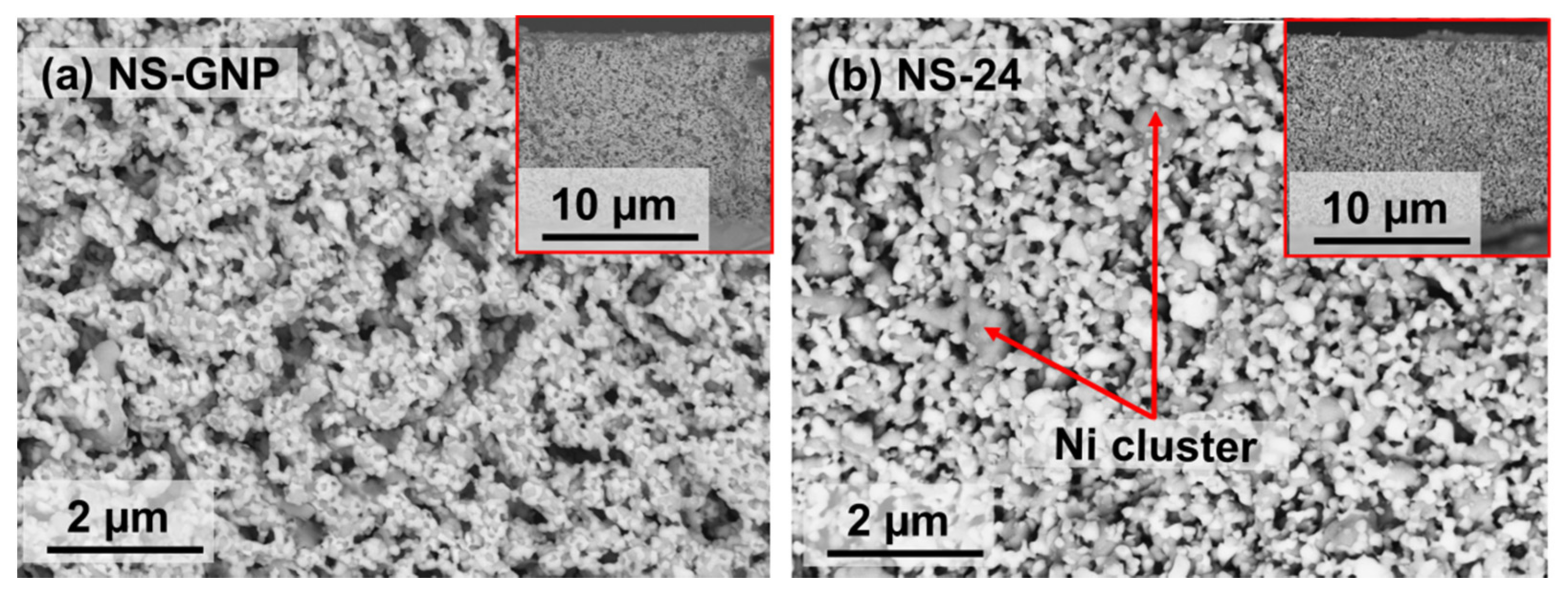
3.3. Microstructural Properties

The surface and cross-sectional images of NS-GNP and NS-24 (with pore former) are shown in Figure 5. The three interfaces were clearly distinguished and distributed uniformly on the microstructure. The white, gray, and black colors represent SDC, Ni, and pores, respectively [20]. A significant difference was observed in the FESEM images in terms of porosity, grain size, and connectivity of the grains (Table 1). The connection among the Ni–Ni, SDC–SDC, distribution of Ni–SDC, and porosity within the anode microstructure is better in NS-GNP than in NS-24.
The connectivity between the white region and gray region is continuous, suggesting the existence of well-connected grains of Ni–Ni and SDC–SDC in the NS–GNP cermet (Figure 5a). The grain-to-grain contact is regarded as having greater importance to facilitate better oxidation of H2 from the Ni contact and mechanical support for Ni from SDC contact. In addition, grain continuity contributes to the length of the triple phase boundary (TPB) and increases the efficiency of the Ni–SDC cermet anode. As shown in Figure 5b, the microstructure of NS-24 exhibits Ni-rich clusters of larger grains (gray) found with smaller SDC grains (white), thereby contributing to degradation in anode performance efficiency. FESEM images of Ni-SDC cermet anode pellets were processed using an image analysis technique developed using the public domain software “ImageJ” to estimate NS-GNP and NS-24 porosities. Figure 5c,d represents the treated FESEM image obtained with the image analysis procedure for quantifying the percentage of porosity. The porosity is depicted in red, the Ni particles in gray, and the SDC particles in white. The pore distribution was uniform with a large number of open pores as evident in NS-GNP. Figure 5d confirms that NS-24 exhibited a slightly denser microstructure than NS-GNP. This result is due to a difference in the grain size distribution and formation of large Ni and SDC particles in the microstructure.
The cross-sectional images of NS-GNP and NS-24 (with pore former) after ion-milling at low (×2000) and high (×5000) magnifications are shown in Figure 6. Ion-milling of Ni-SDC cermet anode has revealed more knowledge about the phase distribution of Ni and SDC grains, grain size, and porosity. In the highly magnified images of NS-24 (Figure 6d), the formation of large Ni and SDC clusters and macro-sized non-spherical sized Ni particles are clearly evident. This finding agrees with the TEM image analysis of the NiO-SDC composite anode powder produced by ball-milling techniques. Figure 6c shows that large Ni particles (gray) are uniformly covered with smaller SDC (white) to form a continuous path. This microstructural feature of the NS-GNP can facilitate a rapid exchange reaction between hydrogen gas and oxide ions by extending the length of the triple-phase boundary associated with phase connectivity [24].
Figure 7 shows the phase map, inverse pole figure (IPF), and misorientation angle of the Ni–SDC grains recorded under the condition of the EBSD technique. The IPF maps revealed the grain size and isolation of large Ni particles in the reduced Ni–SDC cermet anode pellets. In Figure 7c,d, the microstructure of the reduced pellets consists of a mixture of columnar grains and equiaxed grain. The columnar grains can be ascribed to the Ni-clusters and finer small grains to SDC, as shown in Figure 7c,d. The distribution of Ni–SDC constituent phases is evident from the phase map, as shown in Figure 7a,b. The red and green represent Ni and SDC phases. The distribution of Ni and SDC phases were uniform and well-dispersed in NS-GNP samples compared with that of NS-24; this finding is consistent with that of FESEM analysis.

3.4. Mechanical Properties

The hardness and biaxial flexural strength of the Ni–SDC cermet anode after reduction are listed in Table 2. The hardness and flexural strength of all of the Ni–SDC cermet anode samples were consistent with their relative density trends and decreased with increasing porosity (Table 1). Furthermore, the mechanical properties of NS-GNP were higher than that of NS-24 with pore former. It was observed that NS-GNP sample have higher flexural strength and hardness value than that of NS-24 even though the porosity is higher. The flexural strength of NS-GNP sample reached a value of 78 MPa at a porosity of 45%. It appears that the deformation of the NS-GNP cermet anode is significantly more difficult than that of NS-24 because the grain boundary is an obstacle to plastic deformation and mechanical failure. The existence of well-connected grains of Ni–Ni and SDC–SDC in the NS-GNP cermet is the major reason for the significant increase in the mechanical properties of the Ni–SDC cermet anode. The presence of outer SDC particles, in addition to a good connection between SDC–SDC grains, effectively suppress the formation of Ni-clusters in NS-GNP. This also means that the SDC particles tend to provide a supporting framework for Ni particles, thereby ensuring better mechanical strength [25]. Moreover, SDC particles also restrict the aggregation and grain growth of NiO particles during sintering. As a result, a highly porous Ni–SDC ceramic anode with good dispersion of Ni and SDC particles in NS-GNP is produced. Therefore, the optimum mechanical strength can be achieved by minimizing the microstructural flaws, such as grain-to-grain contact, grain size, grain size distribution, porosity, density, and grain boundary constitution through appropriate selection of synthesis techniques. Hanifi et al. [26] also reported that the powder synthesis techniques affect the particle size and distribution, which could possibly affect the mechanical and electrical properties of SOFC anode materials.

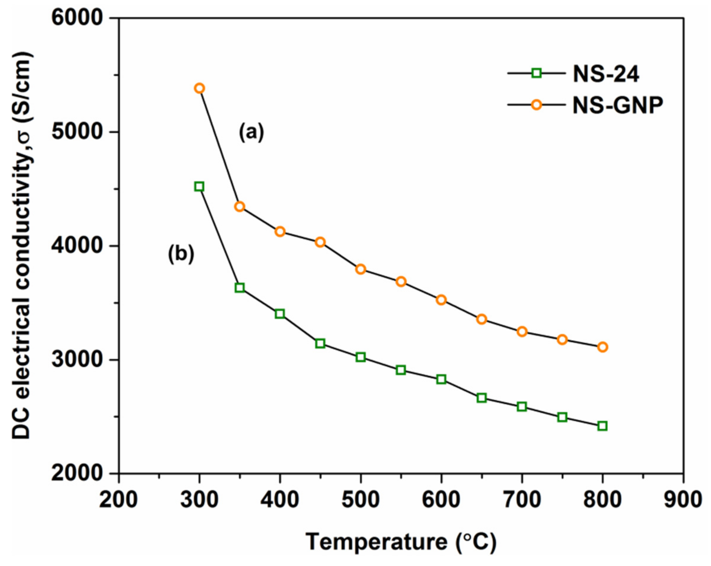
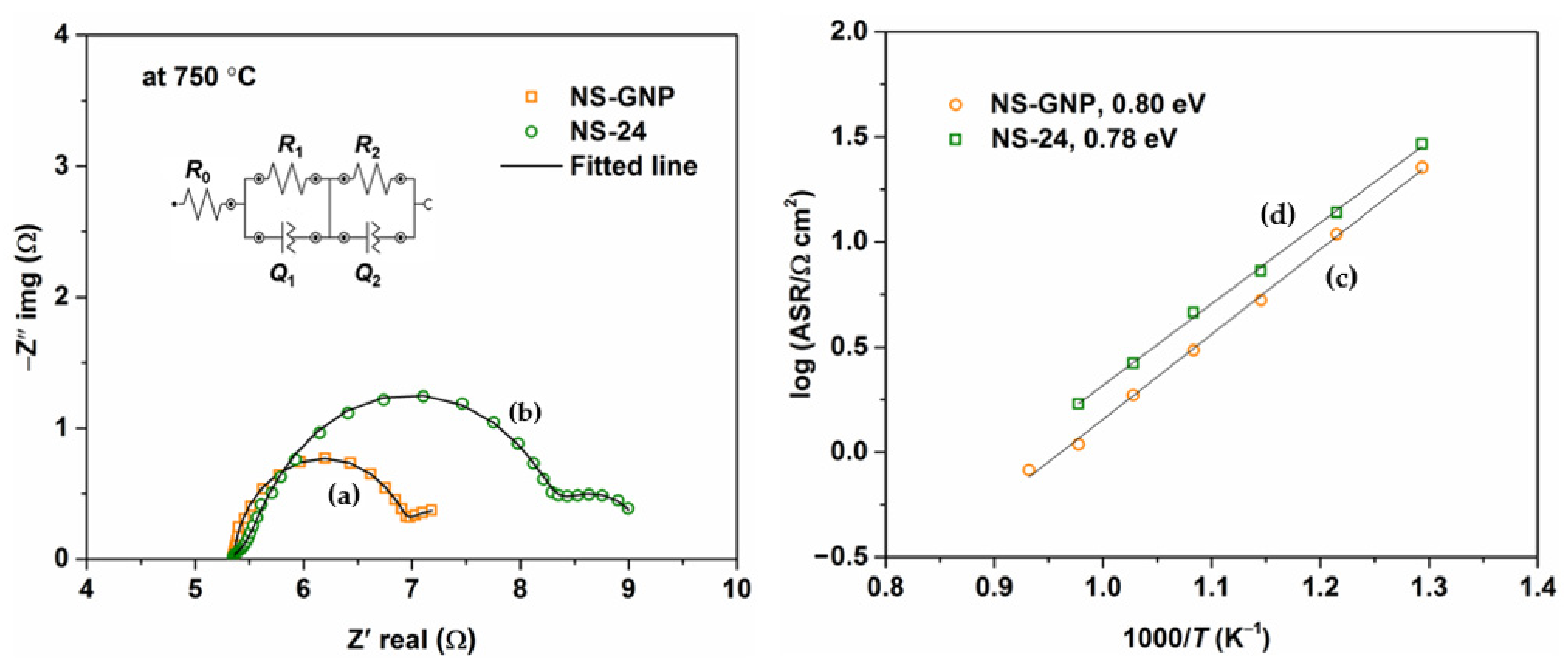
3.5. Electrical Properties

The electrical conductivity of the electro-catalyst, ionic conductivity of the electrolyte, rate of gas diffusion through the electrodes, and charge transfer at the TPB region are key factors that affect the performance of the SOFC anode. In addition, the rate of ionic and electronic transfer is governed by the characteristics of the microstructure, such as grain size and grain continuity. Figure 8 shows the comparison of electrical conductivity of NS-GNP and NS-24 cermet as a function of temperature in H2/3%H2O. The electrical conductivity of both samples decreased with the operating temperature, as expected for metallic electronic conductor materials. This behavior is consistent with the previously reported results. Moreover, both samples exhibited electrical conductivities over 600 S/cm above 600 °C, exceeding the electrical conductivity requirement for the anode material of SOFCs. The maximum electrical conductivity of the NS-GNP and NS-24 cermet anodes was approximately 3111 and 2416 S/cm at 800 °C. Figure 8 shows that the electrical conductivity of the Ni–SDC cermet anode depends strongly on the synthesis techniques. The electrical conductivity of the NS-GNP cermet anode is superior to that of NS-24 at all operating temperatures. Evidently, the electrical conductivity depends on the Ni–Ni grain continuity and well-dispersed Ni–SDC particles. In the case of NS-24, the presence of large Ni clusters and isolated Ni grains has weakened the electrical conductivity. This result shows that the metallic Ni phase is dominant in electrical conductivity relative to the SDC and serves as the primary conduction channel in the Ni–SDC cermet anode.
Figure 9a shows the impedance spectra of NS-GNP and NS-24 cermet anodes measured at 750 °C in a humidified 80% N2 + 20% H2 atmosphere. All of the impedance plots were fitted with an equivalent circuit R0 (R1Q1) (R2Q2), where R is the resistance and Q is the constant phase element, as shown in Figure 9a (insert). The impedance arc intercepts with an actual axis at high frequencies related to the ohm resistance of the electrolyte, electrode, and lead wires, and the right intercept on the actual axis corresponds to the total polarization resistance of the anode (Rp). The polarization resistance of the Ni–SDC cermet anode is generally the sum of the charge transfer process associated with the anode/electrolyte interface or TPB region (R1), and hydrogen dissociation/adsorption or surface diffusion process on the Ni surface (R2). The appearance of two arcs in the impedance spectra shows the two electrode processes of the hydrogen oxidation reaction (HOR). The high-frequency arc for both samples was larger than the low-frequency arc, suggesting that the charge transfer process (R1) probably dominated the polarization resistance.
The area specific resistance (ASR) was calculated using the following equation: ASR = ( R p   ×   A ) / 2 , where Rp (Rp = R1 + R2) is the polarization resistance at the anode surface and anode/electrolyte interface, and A is the active area (1 cm2). The overall size of the impedance spectra of the NS-24 cermet anode was larger than that of the NS-GNP cathode symmetrical cells at all operating temperatures. The temperature dependence of the Ni–SDC cement anode was plotted on the log scale in the form of Arrhenius plots shown in Figure 9c,d. As the operating temperature increases, the value of Rp decreases significantly. The ASR of NS-GNP was lower than that of NS-24 across all operating temperatures. The NS-GNP cermet anode with a well-dispersed Ni–SDC phase in the microstructure exhibited the lowest Rp value of 0.8 Ωcm2 at a measuring temperature of 800 °C. Ideris et al. [14] reported an ASR value of 0.058 Ωcm2 at 700 °C for Ni–SDC cermet anode prepared via GNP. However, the impedance test was conducted in 97%H2/3%H2O atmosphere. Therefore, the obtained ASR of NS-GNP in this study is acceptable because its performance was measured in 20%H2/3%H20 with electrolyte-supported symmetrical cells. The Ni–Ni grain connectivity and distribution of Ni–SDC particles has detrimental effects not only on the mechanical properties of the Ni–SDC cermet anode but also on the catalytic activity of the anode. These microstructural properties increased the TPB density, in which the electrode reaction occurred, compared with the presence of large Ni clusters in the NS-24 morphology.
The FESEM images of the NS-GNP and NS-24 cermet anode films on SDC substrates are presented in Figure 10. The NS-GNP and NS-24 cermet anode samples exhibited significantly different microstructural properties. The NS-24 sample presented a nonhomogeneous distribution of grains and numerous large Ni cluster particles. Moreover, poor Ni–Ni, Ni–SDC, and SDC–SDC connection was observed. This non-uniformity could lead to reduced catalytic activity and, consequently, the HOR reaction at the anode side was significantly disrupted at the reaction sites, such as TPB. The NS-GNP cermet anode with smaller grain size and well-distributed pore structure (Figure 10a) had the lowest Rp value. Reducing the pore size or porosity from the anode microstructure can significantly limit gas diffusion and subsequently increase interfacial polarization resistance [27]. Therefore, the NS-24 cermet anode sample demonstrated higher ASR values at all operating temperatures than NS-GNP. From this perspective, the ball milling method is not a promising method to produce NiO–SDC composite anode powders. The results clearly indicate that the synthesis process plays a crucial role in achieving enhanced microstructure and performance of Ni–SDC cermet anode materials. Therefore, only NS-GNP-based single-cell samples were used to conduct electrochemical tests in hydrogen and methane.

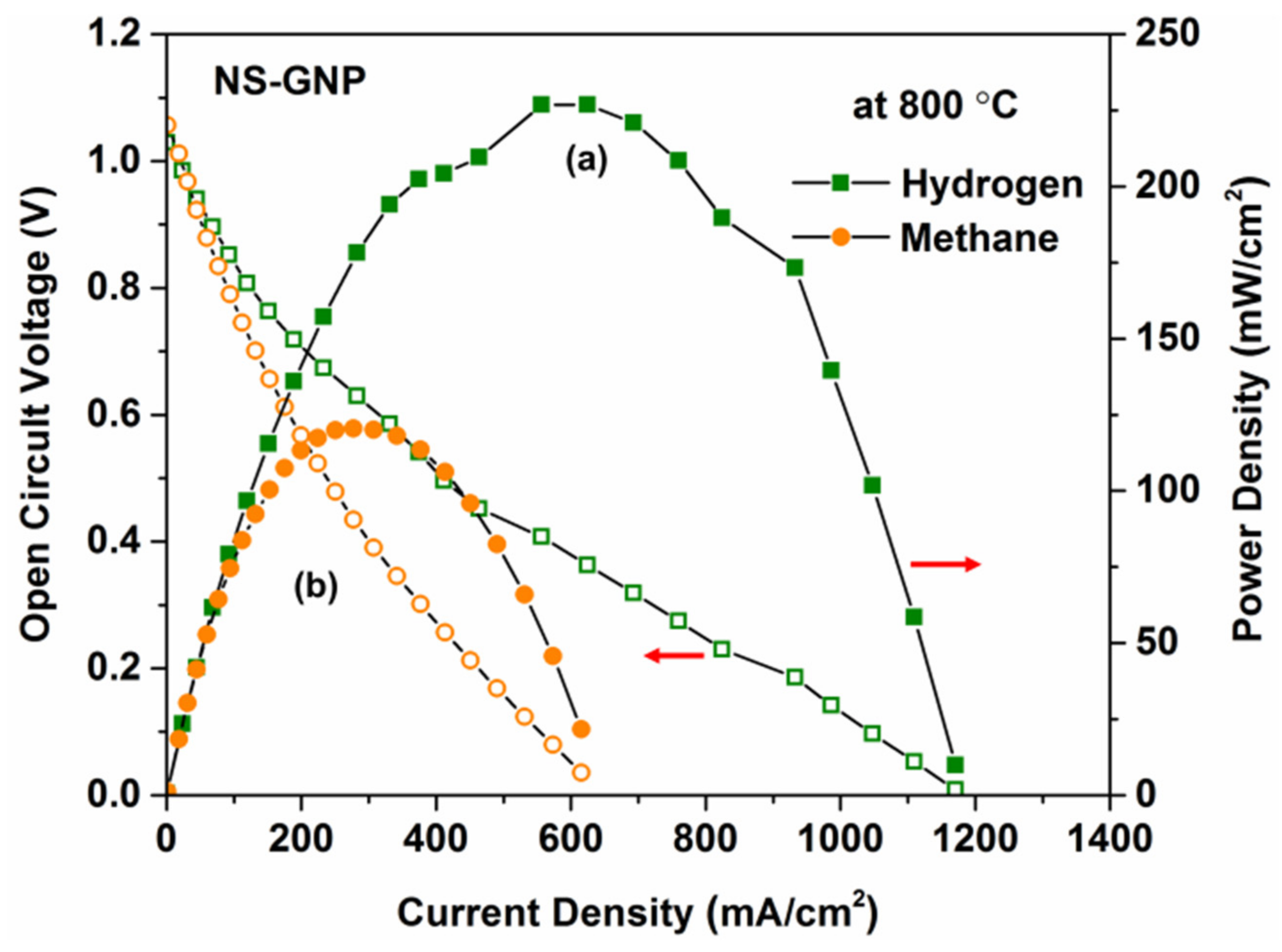
3.6. Electrochemical Performance

The cross-section microstructure of a single cell with the configuration of NS-GNP|YSZ|LSCF is shown in Figure 2a,c. The NS-GNP anode layer is approximately 30 μm thick and adheres well to the YSZ electrolyte substrate, and the thickness of the porous LSCF cathode layer is approximately 10 μm. The YSZ electrolyte substrate is approximately 260 μm thick. The FESEM images demonstrated that the anode microstructure is porous and the well-connected pores are evident. To evaluate the electrochemical performance of NS-GNP cermet anode, the electrolyte-supported cells were tested using humidified H2 and CH4 as the fuel and air as the oxidant at intermediate temperature of 600 °C–800 °C. The cell voltages (V) and the corresponding power densities (P) as the function of current density (I) were measured at 800 °C (Figure 11). The open circuit voltage (OCV) decreased as the operating increased from 600 to 800 °C for both H2 and CH4 fuels. This can be attributed to a trace of gas leakage through the electrolyte or cell [10]. However, the overall OCV value for the cell under H2 and CH4 are close or even higher than the reported values (Table 3). This finding suggests that the YSZ electrolyte does not experience mixed electronic and ion conduction under reducing atmosphere and prevents any internal loss of performance. Therefore, the OCVs of the SOFC with YSZ electrolyte are usually superior to those of SDC electrolyte-supported SOFCs.
The OCV value of NS-GNP with CH4 was higher than that with H2 atmosphere, due to the higher energy density of CH4 fuel. Evidently, the maximum power density decreased as the operating temperature decreased from 800 to 600 °C. This finding is due to an increase in the ohmic resistance of the electrolyte and a slower catalytic electrode as a function of temperature [28]. Wang et al. [29] reported the performance of an Ni–SDC anode with a Ni–SDC|SDC|BSCF cell configuration and found that the cell performs better in dry CH4 at high temperature than in dry H2. The present study indicates that the maximum power density of NS-GNP with CH4 was lower than that with H2 atmosphere at all operating temperatures. The disparities in efficiency between the present and previous studies can be clarified by changes in material, layer thickness, and low H2 and CH4 concentration fuel. However, the values for the Ni-SDC cermet anode demonstrated superior electrochemical performance even at low fuel concentrations compared to those previously reported (Table 3). This result is consistent with the improved microstructure of the anode materials.
The maximum power density of the NS-GNP cermet anode operated in CH4 fuel was lower than that in H2, due to the accumulation and absorption of carbon into the microstructure of the anode. In SOFC, the improved permeability of the fuel gas through the anode microstructure increased the access to the active TPB regions, where the reaction occurred, resulting in reduced activation and concentration polarization. The presence of Ni accelerated the accumulation of carbon deposited on the surface of the Ni, blocked the gas-diffusion pores, and hindered the HOR in the anode [30]. As a consequence, SOFC performance was weakened by the deactivation of nickel cermet active sites for electro-catalytic activity. This carbon accumulation on the microstructure of the anode occurred by methane pyrolysis. To investigate the carbon deposition on the NS-GNP anode, the cross-section of the tested cells in the H2 and CH4 atmosphere was characterized by FESEM and EDX in line-scan mode, as shown in Figure 12. The high concentration of carbon species was observed in the CH4-fuelled NS-GNP anode, but no evidence of carbon accumulation was found in the H2-operated NS-GNP anode. Thus, the performance of the NS-GNP anode was reduced in a methane environment.

4. Conclusions

A NiO–SDC composite anode was synthesized by two different methods, specifically GNP and high-speed ball milling. The microstructural, mechanical, electrical, and electrochemical properties of the resulting Ni–SDC cermet anode were investigated. The results demonstrated that using the ball milling technique led to the formation of large Ni clusters within the microstructure, thereby weakening the mechanical and electrical properties. On the contrary, the GNP technique showed improved grain-to-grain continuity and homogeneous distribution of Ni–SDC grains in the microstructure, resulting in superior mechanical and electrical efficiency. The EBSD characterization results also revealed substantial variation in the microstructure with regard to the synthesis techniques. This finding suggests that the GNP is a successful one-step method for the synthesis of porous NiO–SDC composite anode materials, and minimizes processing time and manufacturing cost. The single cell based on the NiO–SDC composite anode prepared using GNP exhibited a maximum power density of 227 and 121 mW/cm2 at 800 °C in H2 and CH4, respectively.

Author Contributions

Writing—original draft preparation, data curation, methodology, M.A.S.A., methodology, A.Z.Y. and M.T.S.; Writing—review and editing, M.A., A.M. and V.M.K.; Project administration, funding acquisition, supervision, A.M.; All authors have read and agreed to the published version of the manuscript.

Funding

This research was funded by Ministry of Higher Education Malaysia, grant number TRGS/1/2019/UKM/01/1/1.

Institutional Review Board Statement

Not applicable.

Informed Consent Statement

Not applicable.

Data Availability Statement

Not applicable.

Acknowledgments

The authors would like to acknowledge funding from the Ministry of Higher Education Malaysia, through a Transdisciplinary Research Grant Scheme (TRGS) with code TRGS/1/2019/UKM/01/1/1. The authors would also like to acknowledge the support of the Centre for Research and Instrumentation Management, UKM, for the testing equipment.

Conflicts of Interest

The authors declare no conflict of interest.

References

  1. Abd Aziz, A.J.; Baharuddin, N.A.; Somalu, M.R.; Muchtar, A. Review of composite cathodes for intermediate-temperature solid oxide fuel cell applications. Ceram. Int. 2020, 46, 23314–23325. [Google Scholar] [CrossRef]
  2. Wan Yusof, W.N.A.; Abdul Samat, A.; Norman, N.W.; Somalu, M.R.; Muchtar, A.; Baharuddin, N.A. Synthesis and Characterization of Zn-doped LiCoO2 Material Prepared via Glycinenitrate Combustion Method for Proton Conducting Solid Oxide Fuel Cell Application. J. Kejuruter. 2018, SI1, 11–15. [Google Scholar]
  3. Skalar, T.; Zupan, K.; Marinšek, M. Microstructure tailoring of combustion-derived Ni-GDC and Ni-SDC composites as anode materials for intermediate temperature solid oxide fuel cells. J. Aust. Ceram. Soc. 2019, 55, 123–133. [Google Scholar] [CrossRef]
  4. Mahmud, L.; Muchtar, A.; Rao, S.; Jais, A. Processing of composites based on NiO, samarium-doped ceria and carbonates (NiO-SDCC) as anode support for solid oxide fuel cells. Process. Appl. Ceram. 2017, 11, 206–212. [Google Scholar] [CrossRef] [Green Version]
  5. Mishina, T.; Miya, K.; Kikuchi, R.; Sugawara, T.; Takagaki, A.; Oyama, S.T. Ni-SDC Based Cermets for Direct Dry Reforming of Methane on SOFC Anode. ECS Trans. 2017, 78, 1161–1167. [Google Scholar] [CrossRef]
  6. Chien, A.C.; Ye, N.J. Effect of preparation method and particle size of Ni/SDC catalyst on methane oxidation. Catal. Commun. 2021, 106312. [Google Scholar] [CrossRef]
  7. Kan, W.H.; Samson, A.J.; Thangadurai, V. Trends in electrode development for next generation solid oxide fuel cells. J. Mater. Chem. A 2016, 4, 17913–17932. [Google Scholar] [CrossRef] [Green Version]
  8. Che Abdullah, S.S.; Ismail, S.S. Influence of NiO to SDC ratio on the properties of Ni-SDC cermet prepared via reduction process. IOP Conf. Ser. Mater. Sci. Eng. 2019, 701, 1–8. [Google Scholar] [CrossRef]
  9. Yao, X.; Li, P.; Yu, B.; Yang, F.; Li, J.; Zhao, Y.; Li, Y. Hydrothermally synthesized NiO-samarium doped ceria nano-composite as an anode material for intermediate-temperature solid oxide fuel cells. Int. J. Hydrogen Energy 2017, 42, 22192–22200. [Google Scholar] [CrossRef]
  10. Park, S.Y.; Na, C.W.; Ahn, J.H.; Song, R.H.; Lee, J.H. Preparation of highly porous NiO-gadolinium-doped ceria nano-composite powders by one-pot glycine nitrate process for anode-supported tubular solid oxide fuel cells. J. Asian Ceram. Soc. 2014, 2, 339–346. [Google Scholar] [CrossRef] [Green Version]
  11. Shaikh, S.P.S.; Muchtar, A.; Somalu, M.R. A review on the selection of anode materials for solid-oxide fuel cells. Renew. Sustain. Energy Rev. 2015, 51, 1–8. [Google Scholar] [CrossRef]
  12. Choolaei, M.; Bull, T.; Ramirez Reina, T.; Amini Horri, B. Synthesis and characterisation of nanocrystalline CuO–Fe2O3/GDC anode powders for solid oxide fuel cells. Ceram. Int. 2020, 46, 14776–14786. [Google Scholar] [CrossRef]
  13. Sarikaya, A.; Petrovsky, V.; Dogan, F. Effect of the anode microstructure on the enhanced performance of solid oxide fuel cells. Int. J. Hydrogen Energy 2012, 37, 11370–11377. [Google Scholar] [CrossRef]
  14. Ahsan, M.; Irshad, M.; Fu, P.F.; Siraj, K.; Raza, R.; Javed, F. The effect of calcination temperature on the properties of Ni-SDC cermet anode. Ceram. Int. 2020, 46, 2780–2785. [Google Scholar] [CrossRef]
  15. Mukhopadhyay, M.; Mukhopadhyay, J.; Basu, R.N. Functional Anode Materials for Solid Oxide Fuel Cell—A Review. Trans. Indian Ceram. Soc. 2013, 72, 145–168. [Google Scholar] [CrossRef]
  16. Wang, H.; Liu, X.; Bi, H.; Yu, S.; Han, F.; Sun, J.; Zhu, L.; Yu, H.; Pei, L. Effects of NiO on the conductivity of Ce0.85Sm0.15O1.925 and on electrochemical properties of the cathode/electrolyte interface. J. Power Sources 2016, 320, 86–93. [Google Scholar] [CrossRef]
  17. Bobrowski, P.; Faryna, M.; Pędzich, Z. Microstructural Characterization of Yttria-Stabilized Zirconia Sintered at Different Temperatures Using 3D EBSD, 2D EBSD and Stereological Calculations. J. Mater. Eng. Perform. 2017, 26, 4681–4688. [Google Scholar] [CrossRef] [Green Version]
  18. Serrano-Zabaleta, S.; Laguna-Bercero, M.A.; Ortega-San-Martín, L.; Larrea, A. Orientation relationships and interfaces in directionally solidified eutectics for solid oxide fuel cell anodes. J. Eur. Ceram. Soc. 2014, 34, 2123–2132. [Google Scholar] [CrossRef] [Green Version]
  19. Muhammed Ali, S.A.; Anwar, M.; Ashikin, N.; Muchtar, A.; Somalu, M.R. Influence of oxygen ion enrichment on optical, mechanical, and electrical properties of LSCF perovskite nanocomposite. Ceram. Int. 2018, 44, 10433–10442. [Google Scholar] [CrossRef]
  20. Skalar, T.; Zupan, K.; Marinšek, M.; Novosel, B.; Maček, J. Microstructure evaluation of Ni-SDC synthesized with an innovative method and Ni-SDC/SDC bi-layer construction. J. Eur. Ceram. Soc. 2014, 34, 347–354. [Google Scholar] [CrossRef]
  21. Liu, Q.; Dong, X.; Yang, C.; Ma, S.; Chen, F. Self-rising synthesis of Ni-SDC cermets as anodes for solid oxide fuel cells. J. Power Sources 2010, 195, 1543–1550. [Google Scholar] [CrossRef]
  22. Ding, C.; Hashida, T. Synthesis and evaluation of NiO-Ce0.8Sm0.2O 1.9 nanocomposite powders for low-temperature solid oxide fuel cells. Int. J. Hydrogen Energy 2011, 36, 5567–5573. [Google Scholar] [CrossRef]
  23. Drozdz, E.; Stachura, M.; Wyrwa, J.; Rękas, M. Effect of the addition of pore former: Graphite and ammonium bicarbonate on the properties of Ni/Al2O3–3YSZ composite composite materials. J. Therm. Anal. Calorim. 2015, 122, 157–166. [Google Scholar] [CrossRef]
  24. Kishimoto, M.; Miyawaki, K.; Iwai, H.; Saito, M.; Yoshida, H. Effect of composition ratio of Ni-YSZ anode on distribution of effective three-phase boundary and power generation performance. Fuel Cells 2013, 13, 476–486. [Google Scholar] [CrossRef]
  25. Xu, B.; Tian, D. Preparation and characterization of NiO-Sm0.2Ce0.8O1.9 composite nanoparticles for solid oxide fuel cell anodes. In Proceedings of the 3rd International Conference on Mechatronics, Robotics and Automation, Shenzhen, China, 20–21 April 2015; pp. 813–817. [Google Scholar]
  26. Hanifi, A.R.; Laguna-Bercero, M.A.; Sandhu, N.K.; Etsell, T.H.; Sarkar, P. Tailoring the microstructure of a solid oxide fuel cell anode support by calcination and milling of YSZ. Sci. Rep. 2016, 6, 1–9. [Google Scholar] [CrossRef] [Green Version]
  27. Choi, Y.G.; Park, J.Y.; Song, H.; Kim, H.R.; Son, J.W.; Lee, J.H.; Je, H.J.; Kim, B.K.; Lee, H.W.; Yoon, K.J. Microstructure-polarization relations in nickel/ gadolinia-doped ceria anode for intermediate-temperature solid oxide fuel cells. Ceram. Int. 2013, 39, 4713–4718. [Google Scholar] [CrossRef]
  28. Sun, W.; Zhang, N.; Mao, Y.; Sun, K. Facile one-step fabrication of dual-pore anode for planar solid oxide fuel cell by the phase inversion. Electrochem. Commun. 2012, 22, 41–44. [Google Scholar] [CrossRef]
  29. Wang, Z.; Li, Y.; Schwank, J.W. Evaluation of Ni/SDC as anode material for dry CH4 fueled Solid Oxide Fuel Cells. J. Power Sources 2014, 248, 239–245. [Google Scholar] [CrossRef]
  30. Jais, A.A.; Ali, S.A.M.; Anwar, M.; Somalu, M.R.; Muchtar, A.; Isahak, W.N.R.W.; Baharudin, N.A.; Lim, K.L.; Brandon, N.P. Performance of Ni/10Sc1CeSZ anode synthesized by glycine nitrate process assisted by microwave heating in a solid oxide fuel cell fueled with hydrogen or methane. J. Solid State Electrochem. 2020, 24, 711–722. [Google Scholar] [CrossRef]
  31. Yang, C.; Cheng, J.; He, H.; Gao, J. Ni/SDC materials for solid oxide fuel cell anode applications by the glycine-nitrate method. Key Eng. Mater. 2010, 434–435, 731–734. [Google Scholar] [CrossRef]
  32. Xu, D.; Liu, X.; Wang, D.; Yi, G.; Gao, Y.; Zhang, D.; Su, W. Fabrication and characterization of SDC-LSGM composite electrolytes material in IT-SOFCs. J. Alloys Compd. 2007, 429, 292–295. [Google Scholar] [CrossRef]
  33. Li, P.; Wang, Z.; Yao, X.; Hou, N.; Fan, L.; Gan, T.; Zhao, Y.; Li, Y.; Schwank, J.W. Effect of Sn addition on improving the stability of Ni-Ce0.8Sm0.2O1.9 anode material for solid oxide fuel cells fed with dry CH4. Catal. Today 2019, 30, 209–216. [Google Scholar] [CrossRef]
  34. Zha, S.; Rauch, W.; Liu, M. Ni-Ce0.9Gd0.1O1.95 anode for GDC electrolyte-based low-temperature SOFCs. Solid State Ionics 2004, 166, 241–250. [Google Scholar] [CrossRef]
  35. Ideris, A.; Croiset, E.; Pritzker, M.; Amin, A. Direct-methane solid oxide fuel cell (SOFC) with Ni-SDC anode-supported cell. Int. J. Hydrogen Energy 2017, 42, 23118–23129. [Google Scholar] [CrossRef]
  36. Ideris, A.; Croiset, E.; Pritzker, M. Ni-samaria-doped ceria (Ni-SDC) anode-supported solid oxide fuel cell (SOFC) operating with CO. Int. J. Hydrogen Energy 2017, 42, 9180–9187. [Google Scholar] [CrossRef]
Figure 1. Flow chart for the synthesis of NiO–SDC composite anode powders using the: (a) glycine–nitrate combustion process and (b) ball milling process.
Crystals 11 00513 g001
Figure 2. Cross-sectional FESEM images of NiO–SDC/YSZ/LSCF single SOFC: (a) single cell at low magnification, (b) LSCF cathode, and (c) NS-GNP cermet anode.
Crystals 11 00513 g002
Figure 3. XRD patterns of (a) NS-24 and (b) NS-GNP composite anode powders.
Crystals 11 00513 g003
Figure 4. TEM image of NiO–SDC composite anode powders synthesized with different techniques: (a) NS-GNP and (b) NS-24.
Crystals 11 00513 g004
Figure 5. Cross-sectional FESEM images of (a) NS-GNP and (b) NS-24, and analyzed FESEM image with the presence of porosity in red color: (c) NS-GNP and (d) NS-24.
Crystals 11 00513 g005
Figure 6. Cross-sectional FESEM images of Ni-SDC cermet anode after ion milling at different magnifications: (a,c) NS-GNP and (b,d) NS-24.
Crystals 11 00513 g006
Figure 7. EBSD phase map and 2D inverse pole figure (IPF) of the reduced Ni–SDC cermet anode: (a,c) NS-GNP and (b,d) NS-24 cermet anode; reference triangles of each IPF map (insert).
Crystals 11 00513 g007
Figure 8. Electrical conductivities of (a) NS-GNP and (b) NS-24 cermet anode.
Crystals 11 00513 g008
Figure 9. Impedance spectra of (a) NS-GNP and (b) NS-24 measured at 750 °C and an equivalent circuit used to fit in the impedance circuit (inset); Arrhenius plots of the ASR values of the (c) NS-GNP and (d) NS-24.
Crystals 11 00513 g009
Figure 10. Cross-sectional images of the symmetrical cells: (a) NS-GNP and (b) NS-24.
Crystals 11 00513 g010
Figure 11. I–V and I–P characteristics of the electrolyte-supported single cells based upon on NS-GNP: (a) hydrogen and (b) methane.
Crystals 11 00513 g011
Figure 12. FESEM and EDX analyses in line-scan mode at the cross-section of the single cell based on on NS-GNP: (a) hydrogen and (b) methane.
Crystals 11 00513 g012
Table 1. Shrinkage, grain size, relative density, and porosity of Ni–SDC cermet anode prepared using different synthesis techniques.
SampleShrinkage (%)Grain Size (µm)Relative Density (%)Porosity (%)
NiSDC
NS-24 (without pore former)23- 85 ± 0.715 ± 0.7
NS-24 (with 15 wt.% pore former)201.88 ± 0.50.86 ± 0.259 ± 141 ± 1
NS-GNP191.08 ± 0.10.56 ± 0.0455 ± 0.545 ± 0.5
Table 2. Hardness and flexural strength of Ni–SDC cermet anode prepared using different synthesis techniques.
SampleFlexural Strength (MPa)Vickers Hardness (MPa)
NS-24 (without pore former)169 ± 1.3165 ± 1
NS-24 (with 15 wt.% pore former)59 ± 1.133 ± 1.7
NS-GNP78 ± 1.948 ± 1.1
Table 3. Open circuit voltages and maximum power densities of Ni-based composite anode-based single cells tested in hydrogen and methane.
Single Cell Configuration Anode Synthesis MethodFuelOperating Temperature (°C) OCV (V)Power Density (mW/cm2) Reference
Ni−SDC/YSZ/LSCFGNP20%H2/3%H2O8001.03227 This work
(50 vol.% NiO)
Ni−SDC/YSZ/LSCFGNP20%CH4/3%H2O8001.05121 This work
(50 vol.% Ni)
Ni−SDC/SDC/LSCFGNP97%H2/3%H2O8000.8394[31]
(65 wt.% NiO)
Ni−SDC/SDC/SSCGNP100%H2/7500.8100[32]
(65 wt.% NiO)
Ni−SDC/SDC−LSGM/SSCGNP100%H2/8000.83250[32]
(65 wt.% NiO)
Ni−YSZ/Ni/Ni−GDC/GDC/LSCF−GDC/GDCGNP50%H2/3%H2O6000.81413[10]
(45 wt.% NiO)
Ni−SDC/SDC/BSCFBall millingDry 100%H27000.83625[33]
(50 wt.% NiO)
Ni−SDC/SDC/BSCFBall millingDry 100%CH4700-670[33]
(50 wt.% NiO)
Ni−YSZ/Ni/Ni−GDC/GDC/LSCF−GDC/GDCBall milling50%H2/3%H2O6000.80301[10]
(45 wt.% NiO)
Ni−GDC/GDC/LSCFUrea combustion97%H2/3%H2O6000.83225[21]
Ni−GDC/GDC/LSCFBall milling97%H2/3%H2O6000.86400[21]
Ni−GDC/GDC/SSCBall milling97%H2/3%H2O700-402[34]
(65 wt.% NiO)
Ni−SDC/SDC/SSCBall milling97%H2/3%H2O7000.82663[35]
(55 wt.% NiO)
Ni−SDC/SDC/SSCBall millingDry 100%CH47000.83697[35]
(55 wt.% NiO)
Ni−SDC/SDC/SSCBall milling40%CO/60%Co27000.76270[36]
(55 wt.% NiO)
Publisher’s Note: MDPI stays neutral with regard to jurisdictional claims in published maps and institutional affiliations.

