Article

Design of Novel POB/h-BN Co-Filled PTFE Composites with Enhanced Thermal–Mechanical Properties

1
State Key Laboratory for Mechanical Behavior of Materials, Xi’an Jiaotong University, Xi’an 710049, China
2
Wuzhong Instrument Co. Ltd., Wuzhong 751100, China
*
Author to whom correspondence should be addressed.
These authors contribute equally to this work.
Crystals 2021, 11(7), 778; https://doi.org/10.3390/cryst11070778
Submission received: 19 April 2021 / Revised: 25 June 2021 / Accepted: 26 June 2021 / Published: 2 July 2021

Abstract

:
Polytetrafluoroethylene (PTFE) is provided with excellent self-lubricating properties and corrosion resistance. However, the lower thermal resistance greatly limits its high-temperature applications. In the present work, two types of fillers with rigid organic polymers and submicron-sized inorganic hexagonal boron nitride (h-BN) were added to the PTFE matrix. The microstructure and thermal–mechanical properties of PTFE-based composites with different filler types or ratios were comparatively investigated. The results suggested that the polyphenyl ester (POB)/h-BN co-filled PTFE composites exhibited excellent thermal–mechanical properties compared with the polyimide (PI)/h-BN/PTFE materials at high temperature. The optimal ratios of POB and h-BN were 25 wt.% and 5 wt.%, respectively. The Vicat softening temperature of 25 wt.% POB/5 wt.% PI/PTFE composite increased by 41.3% compared to that of pure PTFE, which was due to the cross-linked reticulation structure with regularly distributed pores and higher crystallization degree. The storage modulus increased from 51.99 MPa to 685.76 MPa at 260 °C and reached 187.82 MPa at 320 °C. The uniform distribution of anisotropic orientation of the h-BN flakes showed an obvious pinning effect, and further improved the thermal–mechanical stability of POB/h-BN/PTFE composites.

1. Introduction

As a high-performance engineering material, polytetrafluoroethylene (PTFE) with good thermal stability, chemical resistance and self-lubricating properties has been widely applied in many important parts, such as gear, bearing, pulley, guide rail, piston ring, and sealing elements [1,2,3]. However, PTFE easily slides and undergoes significant plastic deformation, which is ascribed to the symmetrical molecular chain structure with ribbon crystals. The operating temperature of pure PTFE is only in the range of −190 °C~260 °C, and an ambient temperature above 260 °C causes the PTFE to soften rapidly, resulting in low creep resistance, low bearing capacity and a high wear rate at high temperature [4,5]. Therefore, it is of importance to explore an effective method to enhance the softening resistance and mechanical properties of PTFE.
The hybrid modification of single-/multi-component fillers via the molding process is usually used to improve the thermal–mechanical properties of PTFE. The types of fillers can be divided into two categories according to the material feature, such as inorganic fillers and metal fillers [6,7]. Based on the morphology and grain sizes of fillers, they are classified into micron, submicron, nano-scale spherical or fiber shaped fillers [8,9,10]. Among them, multi-component inorganic nano-fillers are often used to improve the softening resistance of PTFE. ZrO2 and Au nano-particles served as friction modifiers to reinforce the friction and wear properties of PTFE [11,12]. Recently, hexagonal boron nitride (h-BN) has also been a reliable candidate to be an inorganic filler with superior comprehensive performance for high-temperature applications [13]. Its crystalline form is similar to the graphite or MoS2 material [14]. Compared to the other fillers, h-BN shows excellent oxidation resistance and higher anti-corrosion performance [15]. Furthermore, some studies suggest that the addition of h-BN not only improved the softening resistance of PTFE, but also significantly enhanced its tribological properties [16,17]. The effect of h-BN particles’ size, concentration, aggregation, and orientation on the anisotropic thermal diffusivity is also analyzed [18]. However, the interfacial compatibility between the PTFE matrix and h-BN fillers is considered to be an important question. This is due to the fact that poor interfacial compatibility can introduce some defects into composites, which greatly limits the thermal dissipation efficiency of the interface [19,20]. Therefore, silane coupling agents are usually employed to reduce the surface hydrophilicity of h-BN fillers and improve the interfacial compatibility between the PTFE matrix and h-BN fillers [21,22,23,24].
The blend modification of various polymers is an effective method to improve the properties of the matrix. The similar feature of the solubility and surface tension of materials should be considered when adding various polymers to the PTFE matrix [25]. Currently, the widely used blended materials are polyimide (PI) [26], polyphenylene ester (POB) [27], polyetheretherketone (PEEK) [28,29], and other polymers [30,31,32,33]. POB and PI can be blended with PTFE in any proportion due to the excellent combination, and the rigid molecular structure of POB and PI further plays a role in inhibiting the softening of PTFE-based composites [26,27,34,35,36,37,38]. Recently, Han et al. designed a series of organic–inorganic crosslinked hybrid membranes, which provided a reference for the preparation of higher performance multi-component composites. In the presence of both a rigid crosslinked structure and inorganic phase, the composites possessed high thermal stability and mechanical properties [21,39]. Furthermore, Xie and Pan et al. investigated the synergistic effect of multi-component fillers with different volume ratios in the PTFE matrix [40,41]. POB/PI with a benzene structure was also proved to be blended with the PTFE in a wide range [36,37].
Motivated by the above considerations, the multi-component system of POB/PI and h-BN co-filled PTFE-based composites is expected to obtain excellent thermal–mechanical properties. However, there are few studies on the relationship of both the microstructure/crystallization and performance of these composites. Therefore, novel POB/h-BN or PI/h-BN co-filled PTFE composites with different addition ratios are designed and fabricated via the cold-pressing and sintering method in this paper. The effects of microstructure and crystal orientation on the thermal–mechanical properties of composites were systematically investigated to reveal the synergistic enhanced mechanism of POB/h-BN-PTFE composites.

2. Experimental Procedure

2.1. Materials

The original PTFE and POB powders were purchased from the same company (Shandong Jiashan Fluorui Engineering Material Co., Ltd., Jiaxing, China). The h-BN powder (99.9%) was obtained from Qinhuangdao ENO High-Tech Material Development in Hebei Province of China. The KH560 coupling agent (≥99.0%) was supplied by Guangzhou Epoxy Material Technology Co., Ltd. (Guangzhou, China). PI powder was obtained from Wuhan Zhisheng Science & Technology Corporation (Wuhan, China).

2.2. Preparation of Samples

Preparation process of samples is shown in Figure 1. Firstly, the original PTFE powder was processed by mechanical stirring at a high speed and was uniformly dispersed, as shown in Figure 1A. In order to reduce the agglomeration of h-BN powder and improve the interfacial compatibility with PTFE matrix, a KH560 coupling agent was added into a solution. The mass ratio of ethanol and aqueous solution was 3:1. Then, h-BN powder was dispersed in the mixed solution and the blended suspension was stirred magnetically at 60 °C for 3 h. The hydrolysis and dying processes are shown in Figure 1B. The KH560 molecule hydrolysis was mainly physically absorbed on the surface of h-BN. The dried process could promote covalent bonds between KH560 and h-BN. Subsequently, the mixed powder with a certain percentage, including processed PTFE, original POB, PI, modified h-BN, was homogeneously mixed in a single-phase series motor (see Figure 1C). The rotation speed was 4000 rpm for 10 min. Finally, PTFE-based hybrid composites were prepared via a cold-pressing and sintering method, as shown in Figure 1D. The cold-compression molding was carried out at room temperature with a pressure of 40 MPa for approximately 10 min. The sintering process consisted of four stages, such as 200 °C for 2.5 h, 270 °C for 3 h, 340 °C for 30 min and 380 °C for 3 h. The heating rate of each stage was 2 °C/min. A series of PTFE-based composites with different compositions are listed in Table 1.

2.3. Characterization

Microstructure of samples was observed using scanning electron microscopy (SEM, VEGAII XMU, Tescan, Czech Republic). Crystallinity degree of samples was analyzed using X-ray diffraction (D8 DISCOVER, Series 2; Bruker, Madison, WI, USA) with a Cu-Kα type X-ray source and wavelength of 1.54056 Å. The diffractometer was operated at a diffraction angle (2θ) ranging from 10 to 90°, with a scanning speed of 0.008°. Differential scanning calorimetry (DSC) and thermogravimetric analysis (TGA) (METTLER TOLEDO TGA/DSC3+, Shaanxi Langrun International Trade Co. Ltd., China) were used to measure the thermal decomposition temperature and melting point of materials. The test was conducted in an air atmosphere from 30 °C to 700 °C with a heating rate of 10 °C/min. The thermal diffusivities ( α ) and the specific heat capacity ( C p ) of samples were measured using a laser flash apparatus (LFA 427, Netzsch, Searle, Germany) at the temperature of 25 °C and 260 °C. Each specimen was measured four times at the corresponding temperature. The density ( ρ ) of samples was measured through the Archimedes method. Thus the thermal conductivity ( λ ) was calculated by the following equation:
λ = ρ C p α
Dynamic thermomechanical analysis mainly included the glass transition and melting test, secondary transition test, frequency effect, optimization of the transition process, fatigue test, and material aging. The standard test mode of a dynamic thermomechanical analysis (DMA) instrument (Netzsch DMA242E, China Teaching Equipment Co. Ltd., Shanghai, China) was used to test the glass transition and melt transition temperature of materials as well as the change in storage modulus with temperature. The test conditions were in an air atmosphere, the heating rate was 5 °C/min, and the test temperature ranged from 30 °C to 330 °C. Creep mode was carried out to test the high-temperature compression creep performance at 260 °C for two hours under 12 N loading.
In order to further characterize the high-temperature compression creep behavior, a self-made high-temperature compression creep tester was used to apply a normal load of 0.02485 MPa. The diameter and thickness of compressive creep were 17 mm and 6 mm, respectively. The Vicat softening temperature of samples was measured using a Vicat softening temperature tester (40-197-100, Autostrong, Coesfeld, Germany). The thickness of samples was controlled at 5 mm. Test conditions were a load of 50 N and a 120 °C/min heating rate.

3. Results

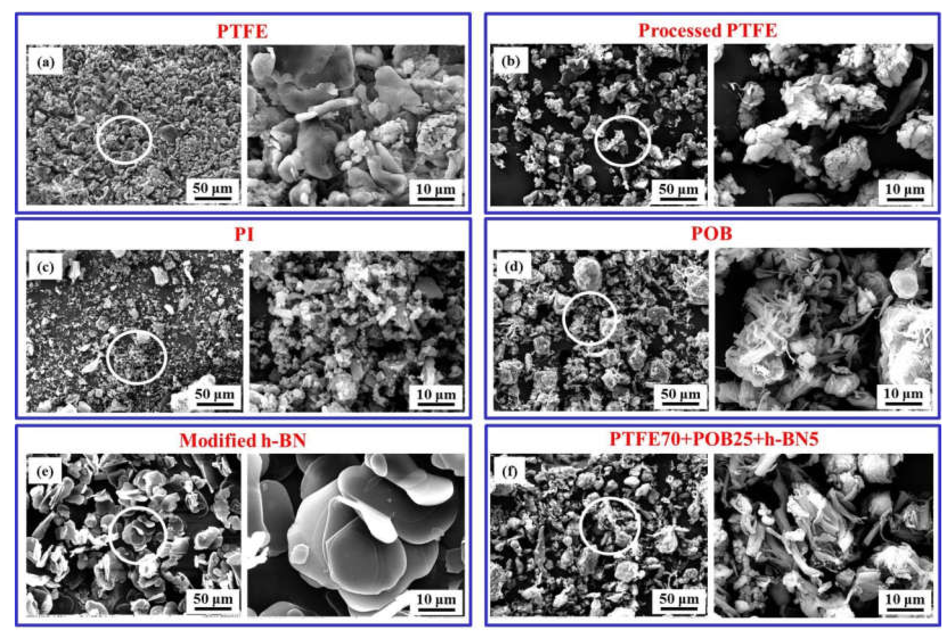
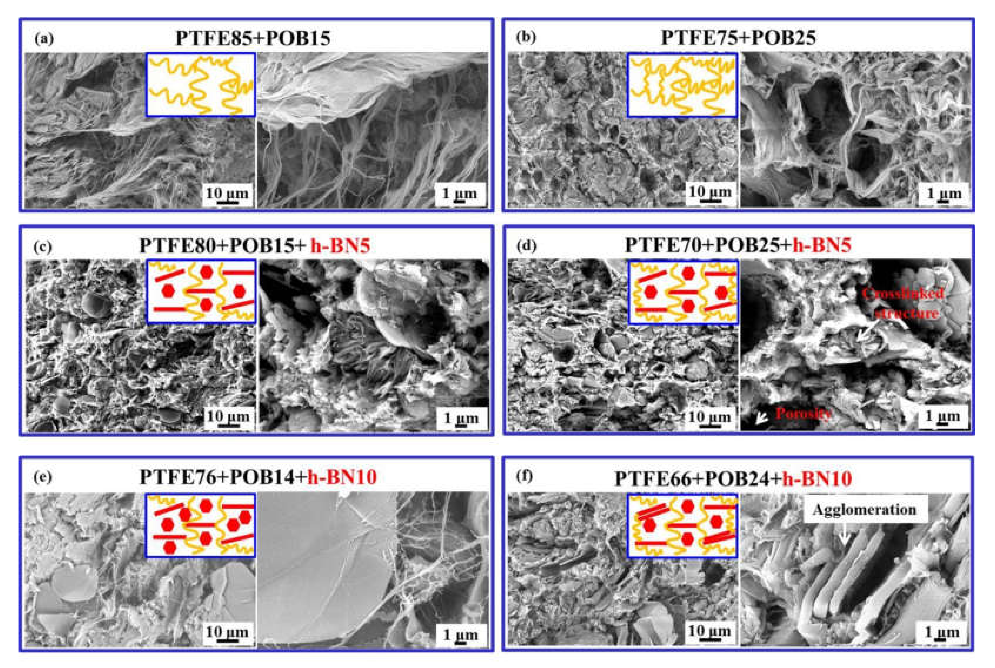
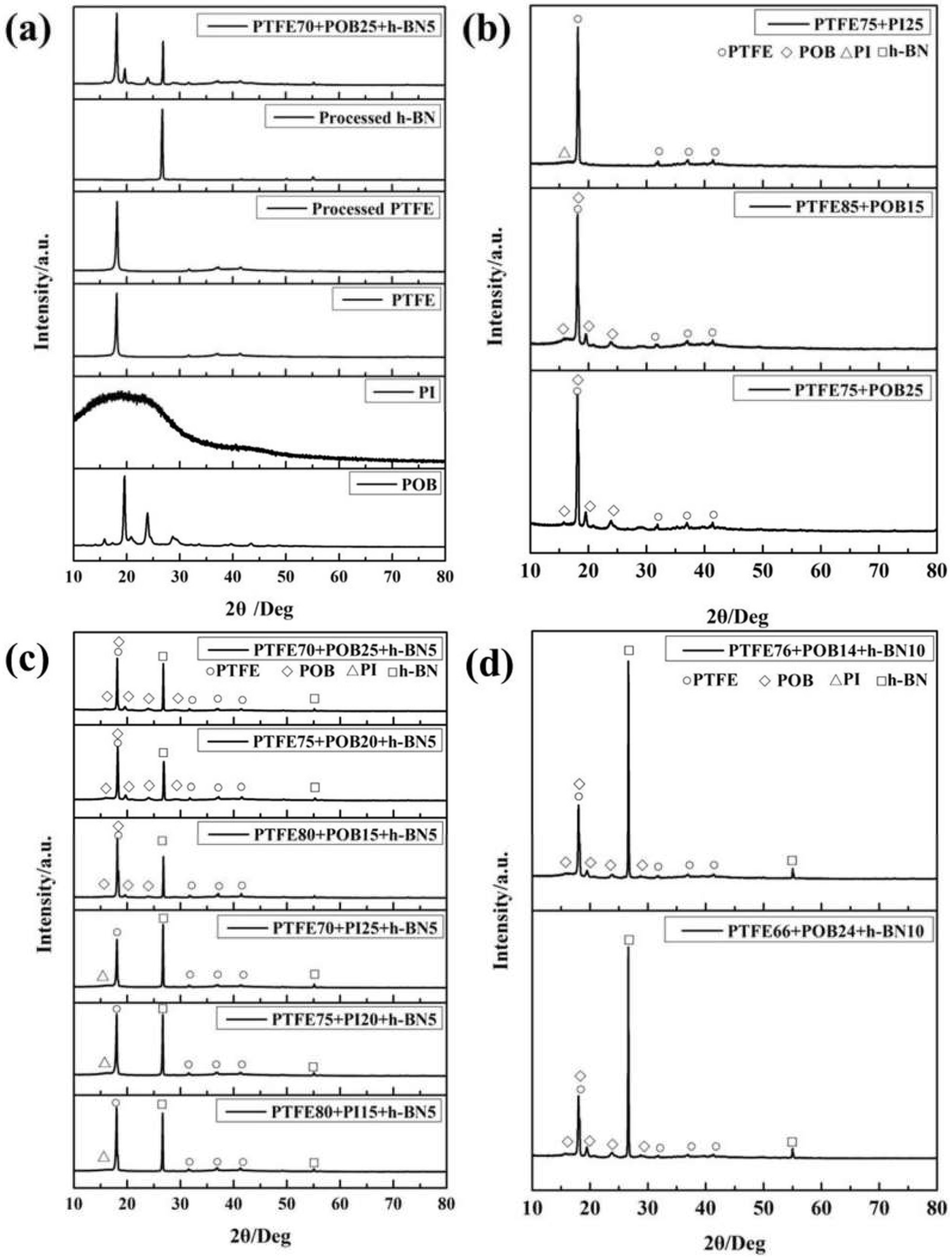
3.1. Microstructure of Powders

The morphologies and high-magnification images of original powders are shown in Figure 2. As seen from Figure 2a, the PTFE white flocculus exhibited an agglomerating and flaky morphology. After mechanical stirring, it was changed into a dispersive morphology with a particle size distribution of 5–10 μm, as shown in Figure 2b. The original PI and POB powder morphologies are shown in Figure 2c,d. Compared with the finer ribbon shape inside POB spherical powder, PI exhibited irregular shape. For the modified h-BN, it showed a typical flaky morphology with lateral sizes ranging from 5 to 30 μm (see Figure 2e). For the mixed powder with 25 wt.% POB and 5 wt.% h-BN, as shown in Figure 2f, it was observed that the POB particles were homogeneously distributed in the powder.

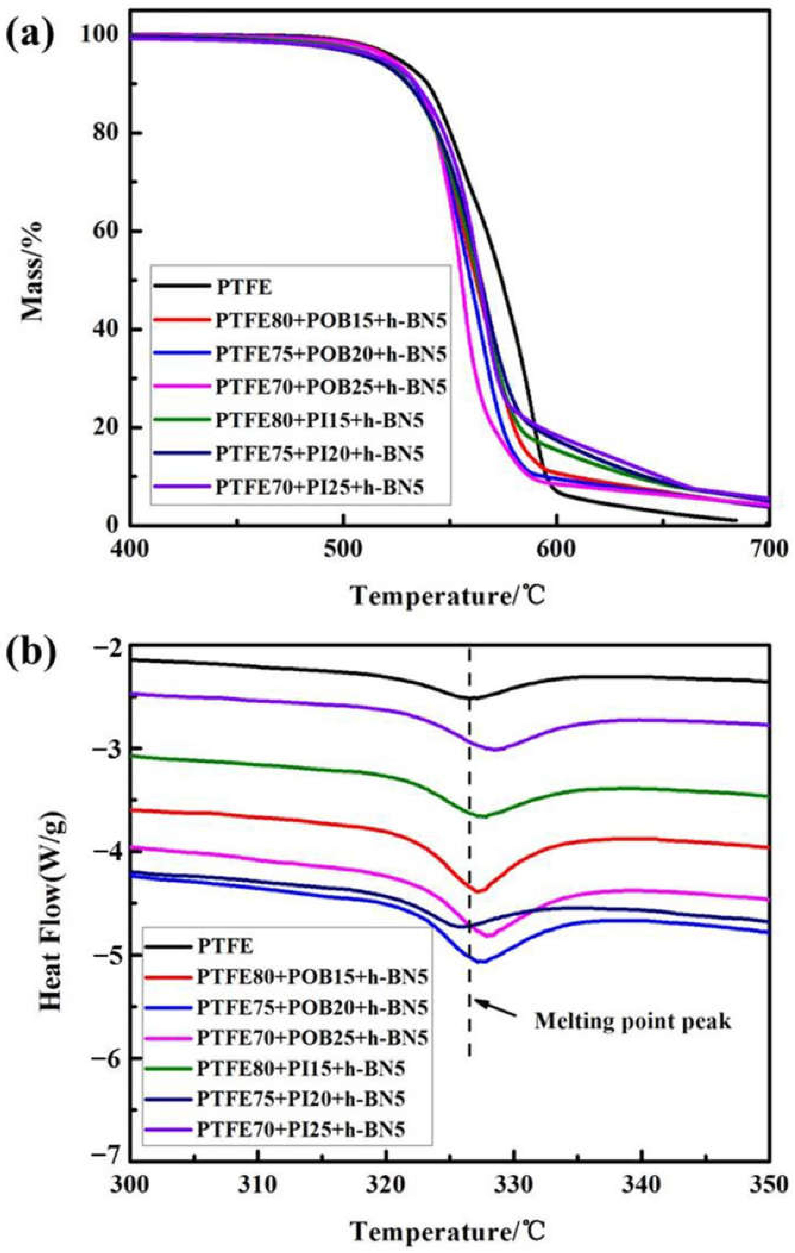
3.2. Thermal Stability and Melting Point

Thermogravimetric analysis was employed to investigate the degradation kinetics and heat resistance of samples. Figure 3 depicts the thermal weight loss and DSC curves of pure PTFE and PTFE-based composites. As seen from Figure 3a, the thermal decomposition temperature of all samples reached 500 °C. Compared with the pure PTFE, the melting point of PTFE-based composites increased to some extent, as shown in Figure 3b, indicating that the dissolution of PTFE was suppressed. The melting point of the 25 wt.% POB/5 wt.% h-BN co-filled PTFE composite and 25 wt.% PI/5 wt.% h-BN co-filled PTFE composite was 328.00 °C and 328.33 °C, respectively.

3.3. Vicat Softening Temperature

The Vicat softening temperature is one of the indicators that can effectively evaluate the softening resistance of materials, and the obtained results are listed in Table 2. It can be seen from Table 2 that the softening temperature of PTFE-based composites was obviously higher than that of pure PTFE. The composite with 25 wt.% POB/5 wt.% h-BN exhibited a higher softening temperature. Compared with pure PTFE, the softening temperature increased from 92 °C to 130 °C and increased by 41.3%. A higher softening temperature is beneficial to the improvement of thermal stability.

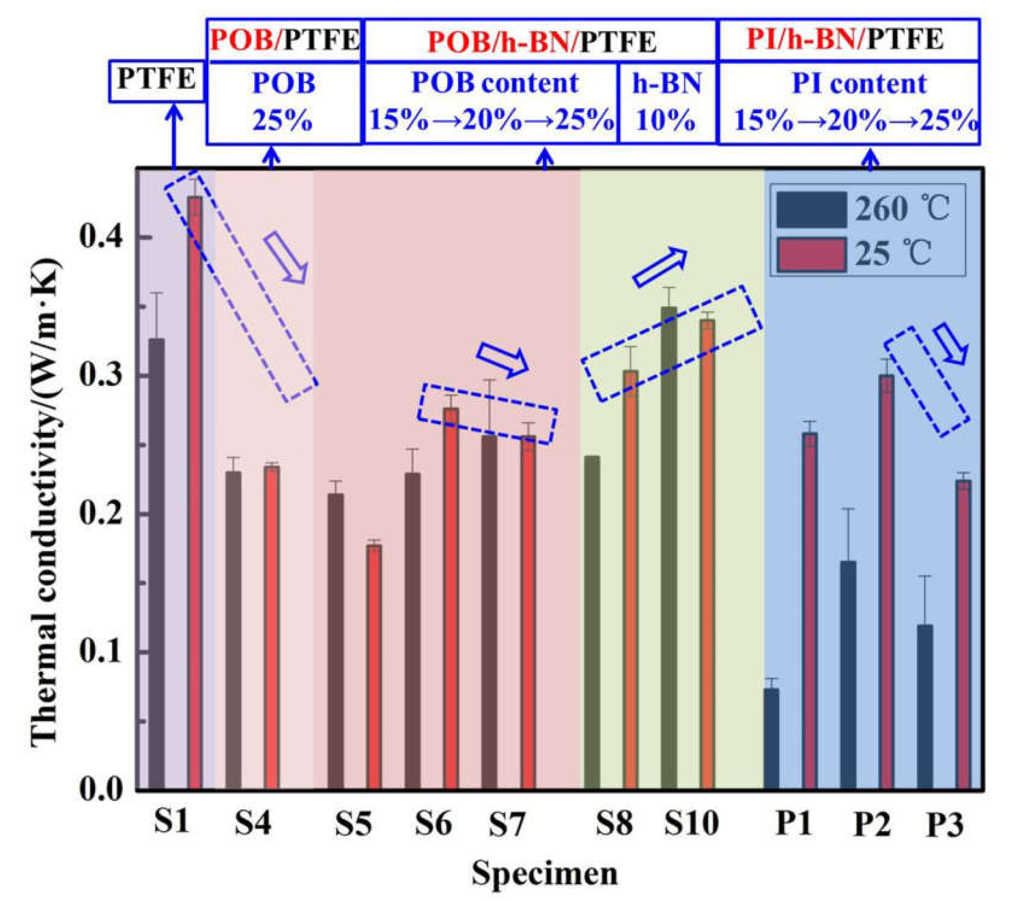
3.4. Thermal Diffusivity and Thermal Conductivity

Table 3 gives the thermal diffusivity and thermal conductivity of pure PTFE and PTFE-based composites. At room temperature, the thermal diffusivity of PTFE composites increased with increasing the content of PI or POB. Unlike the POB/h-BN/PTFE composites, in which a further increase in POB content resulted in an increase in thermal conductivities, the thermal conductivities of PI/h-BN co-filled PTFE composites firstly increased and then decreased. Furthermore, it is found that the thermal conductivity of composites linearly increased with the increase in h-BN content from 5 wt.% to 10 wt.%. When the test temperature reached 260 °C, the thermal conductivities of POB/h-BN/PTFE composites steadily decreased, whereas POB/h-BN/PTFE composites appear to show an opposite trend.

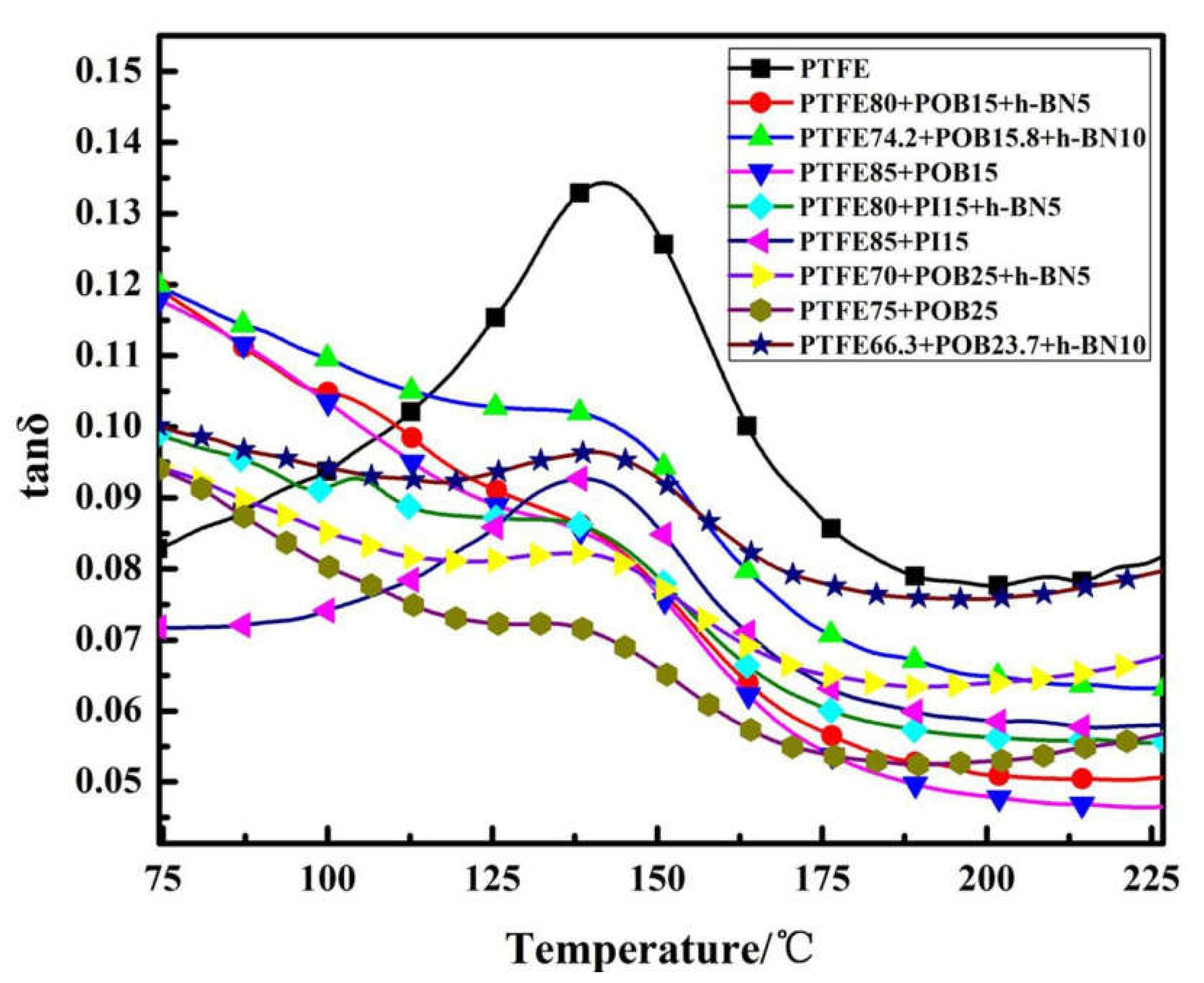
3.5. Dynamic Thermomechanical Analysis

The standard test mode of DMA was used to obtain the glass transition temperature or melt transition temperature of samples, the change in storage modulus as a function of temperature and the change in loss factor and storage modulus at elevated temperatures [42]. The loss factor (tan δ) refers to the ratio of the loss modulus (E″) to the storage modulus (E′) of the material during the deformation process. The larger the value of the loss factor, the better the mobility of the polymer molecular chain, and plastic deformation easily occurs. Based on this theory, the dynamic thermomechanical analysis of the loss factor diagram was carried out and is shown in Figure 4. As seen from Figure 4, the loss factor of the POB/PI modified composite was lower than that of pure PTFE, suggesting that the movement of molecular chains within PTFE is hindered at the glass transition temperature point due to the addition of rigid molecular chains. Meanwhile, the tan δ value after the addition of POB was much lower, indicating that the effect of POB on the heat resistance of PTFE was more obvious than that of PI. With the increase in POB content, the tan δ value further decreased. The optimal proportion of POB content was 25 wt.%.
Storage modulus (E′) refers to the energy stored in the materials through elastic deformation, which reflects the elastic component of the material’s viscoelasticity and characterizes the corresponding stiffness. The increase in storage modulus is beneficial to improve the softening resistance of materials [41,42]. Figure 5a gives the storage modulus of pure PTFE and POB/PI/h-BN modified PTFE composites as a function of temperature. Compared with the storage modulus of pure PTFE (51.99 MPa), the storage modulus of single-/multi-component composites was improved. Figure 5b shows the storage modulus histogram of single-/multi-component filled composites at 260 °C and 300 °C from Figure 5a. As shown in Figure 5b, with the increase in temperature, the storage modulus of samples showed a downward trend. In addition, POB/h-BN/PTFE composites have a higher storage modulus than that of PI/h-BN/PTFE composites. The PTFE composite filled with 25 wt.% POB/5 wt.% h-BN displayed the highest storage modulus and the corresponding value was 187.82 MPa. Figure 5c and d show the storage modulus curves of submicron-sized h-BN filler with different contents and the corresponding storage modulus at 260 °C and 300 °C. It can be seen that the increase in h-BN content causes the increase in the storage modulus. However, when the content of h-BN reached 10 wt.%, the storage modulus decreased at least 53 MPa.

3.6. High-Temperature Creep Behavior

High-temperature compression creep resistance is an important index for evaluating the softening resistance of materials. By comparing the storage modulus of materials with different proportions, the PTFE-based composites with 25 wt.% POB/5 wt.% h-BN had a better softening resistance. A 12N load was applied to the samples and kept at 260 °C for 2 h. The high-temperature compression creep values were obtained as shown in Table 4 and Figure 6a. The compression creep of pure PTFE was 4.35%, while the composite with 25 wt.% POB and 5 wt.% h-BN significantly decreased by 33%. The creep curve measured by a self-made simple device is shown in Figure 6b. The shape of the composite with 25 wt.% POB and 5 wt.% h-BN kept relatively stable with the increase in temperature, suggesting an improvement in softening resistance.

4. Discussion

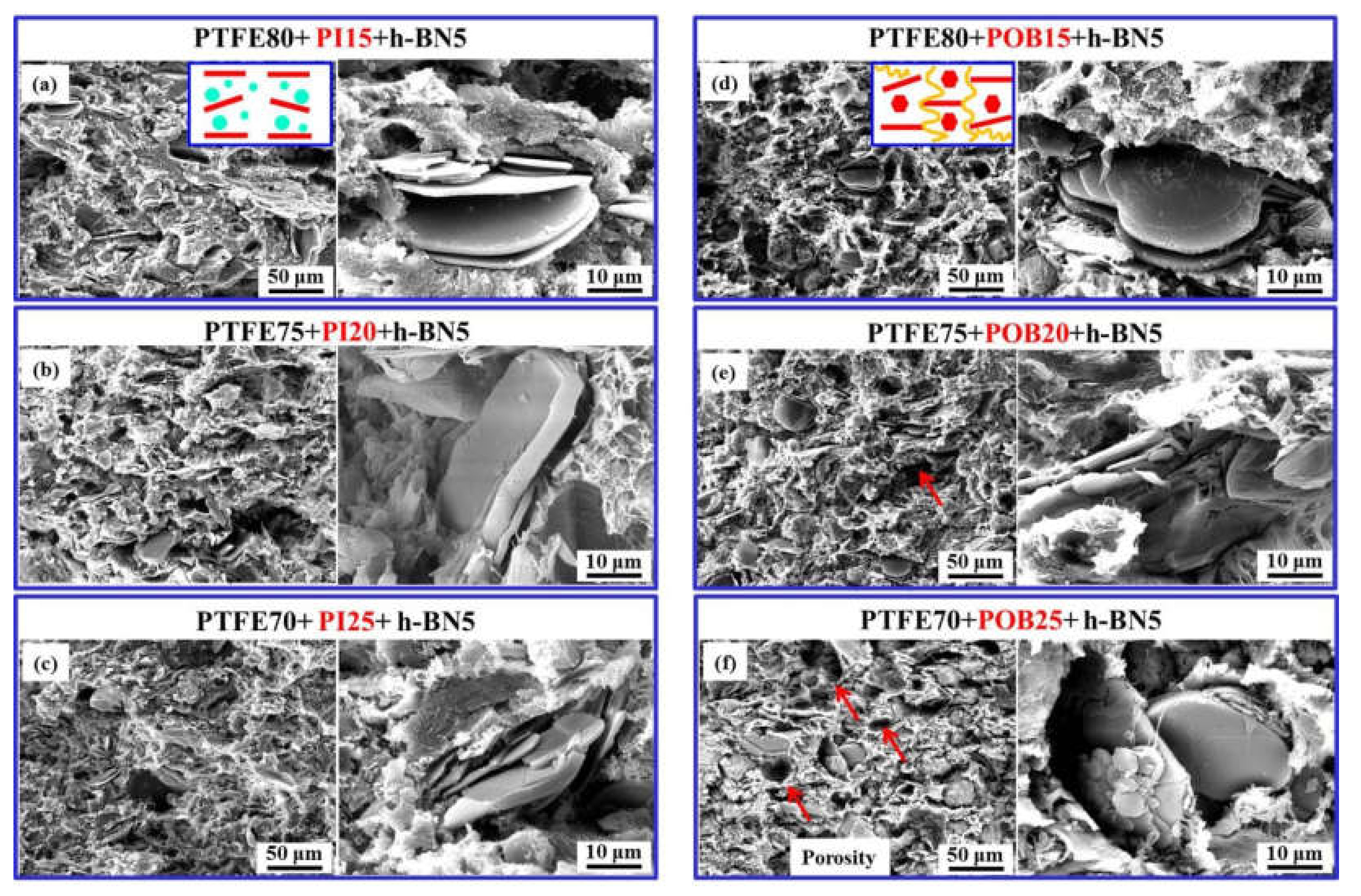
4.1. Effect of Morphology and Molecular Structure on the Thermal–Mechanical Properties

The experimental results suggest that the addition of POB/PI or h-BN multi-component fillers obviously promoted the thermal–mechanical properties of PTFE. Especially, the melting point and Vicat softening temperature of the composite with 25 wt.% POB and 5 wt.% h-BN display a higher value of 328 °C and 130 °C, respectively. Additionally, the storage modulus of the optimal content was 187.82 MPa. This can be originated from the molecular chains of polymer materials. The melt transition is defined as the process in which the polymer changes from a higher elastic state to a viscous fluid state. Viscous fluid chains slide with each other, so the melt transition is related to the molecular chain structure. The molecular chain of PTFE was flexible, while that of POB filler was rigid benzene rings. The POB with rigid backbones was hardly melted at a high temperature and acted as a physical support point to further prevent the sliding of the PTFE molecular chains [26,37]. Furthermore, with the increase in POB content, the movement of molecular chains became more difficult. Consequently, the melting point and Vicat softening temperature of the composites were effectively improved, which finally increased their storage modulus.
The excellent thermal–mechanical properties are closely related to the microstructure. SEM images of the polished cross section and fracture surface of pure PTFE and PTFE-based composites are shown in Figure 7. As seen from Figure 7a,b, the PTFE exhibited a typical ribbon-shaped crystal structure. Some micro-cracks are found in the ribbon-shaped structure and displayed an anisotropic propagation direction. Furthermore, the fractured surface of pure PTFE presented a dimple-like structure, which was beneficial to retard the crack growth speed (see Figure 7c,d). For the microstructure of PTFE composites filled with 25 wt.% PI, it can be seen from Figure 7e–f that the PI spherical micro-clusters were uniformly dispersed in the PTFE matrix. However, POB components as long chains were usually cross-linked together and are shown in Figure 7g–h. The crosslinked reticulation structure caused a significant enhancement in the Vicat softening temperature.
Figure 8 shows the microstructure of POB/h-BN or PI/h-BN multi-component PTFE composites when the h-BN was added into the above composites. It is interesting to note that some h-BN flakes exhibited the anisotropy in distribution. For PI/h-BN composites with different PI contents, the orientation direction of h-BN in Figure 8a–c was perpendicular to the thickness direction. As seen from Figure 8d–f, POB/h-BN not only retained the above h-BN orientation angle, but also consisted of the whole hexagonal surface direction. The multi-component fillers were changed into a more compact structure compared with single-component filler. The composite with 25 wt.% POB and 5 wt.% h-BN showed a cross-linked structure with regularly distributed pores, which was further conducive to higher thermal stability and thermal conductivity (see Figure 8f and Table 3). In addition, the h-BN as the second phase possessed the pinning effect of phase boundaries, which enhanced the mechanical properties [43,44]. SEM images of the fracture surface for PTFE composites filled with different h-BN contents are shown in Figure 9. When the h-BN content reached 10 wt.%, the cross-linked structure was disturbed by high-content h-BN flakes. In addition, the more irregular arrangement and anisotropic orientation of h-BN flakes are found in Figure 9e and f. The high magnification image from Figure 9f further confirmed the agglomeration phenomenon of h-BN flakes. Agglomerates acted as a strong stress concentrator, which essentially resulted in the decline of thermal–mechanical properties [45,46].
Figure 10a shows the FTIR spectra of KH560 modified h-BN powder. Two strong peaks were found at 1376 cm−1 and 811 cm−1, which corresponded to the in-plane stretch vibration and out-plane bending vibration of B–N. The new absorption peak of Si–O stretching at 1024 cm−1 proved the presence of a silane coupling agent on the surface of the powder [24]. For the pure PTFE, the stretching vibration peaks at 1200 cm−1 and 1142 cm−1 were assigned to the C–F and C–C bonds. With the addition of the PI component, as seen from Figure 10b, the stretching vibration peaks corresponded to imide groups at 1776 cm−1 (C–O), 1717 cm−1 (C–O) and 1374 cm−1 (C–N–C) [47]. With the addition of the POB component, as seen from Figure 10c, the existence of C=O, -C=C-, C–O–C, and the benzene ring of POB was confirmed by the strong bands at 1750, 1520, 1080, 750, and 900 cm−1, respectively. The addition of h-BN significantly reduced the signal of the absorption peak of POB. With the increase in h-BN content, the intensity absorption peak for N–B and the benzene ring was improved accordingly. These results suggested that the formation of the above cross-linked reticulation structure was due to physical forces.

4.2. Effect of Crystallization Orientation on Thermal–Mechanical Properties

To further investigate the additional filler for the crystallization and orientation variation of h-BN flakes, X-ray diffraction patterns of original powder and PTFE-based composites were obtained. Figure 11a illustrates that the crystallization peaks of POB powders were more obvious than those of PI powder. The crystallization degree of POB/PTFE composites further increased after the cold-pressing and sintering process, as seen from Figure 11b. The peaks at about 18.5°, 31.5°, 37.0° and 41.3° were attributed to the reflections of (100), (110), (107) and (108) lattice planes of PTFE, respectively. There were three new peaks at about 16.1°, 19.8° and 24.2° in the POB/PTFE composites, which were assigned to the reflections of (010), (110) and (200) lattice planes of POB, respectively [48]. The different contents of POB had no effect on the crystallization degree. There was only a little amorphous peak in the PI/PTFE composites at the diffraction angle of 17°.
Figure 11c displays the XRD patterns of POB/PI/h-BN modified PTFE-based composites. With the addition of 5 wt.% h-BN in the POB/PTFE or PI/PTFE composite, it is clearly observed that two evident peaks at 26.9° and 41.6° corresponded to the (002) and (100) lattice planes of h-BN, respectively. The intensity ratio of the (002) and (100) peaks elucidated the orientation degree of h-BN filler in the POB/PTFE or PI/PTFE composite [32,33,45]. With the increase in POB and PI content, the (002) peak of h-BN fillers gradually increased, and the (100) peak of PTFE relatively decreased. When the addition of h-BN flakes was kept at 10 wt.%, the changing tendency was more obvious. The higher intensity of (002) and (100) planes indicated the h-BN flakes were highly in-plane oriented in the PTFE/POB composites. The reasons were attributed to the lubricious nature of h-BN flakes, which made them easily orient perpendicular to the axial pressure during the process of cold-compression [48,49]. Moreover, the addition of h-BN flakes played a role in the heterogeneous nucleation to facilitate the crystallization rate, so the crystallinity of POB/h-BN/PTFE composites increased with the increase in filler content. For the 10 wt.% h-BN/24 wt.% POB/PTFE composites, the ratio of (002) and (100) was as high as 15, which suggested a high in-plane orientation degree of h-BN flakes through the POB/PTFE composite.

4.3. Thermal Stability of PTFE-Based Composites with Multi-Component Fillers

034 W/m·K and 0.429 ± 0.013 W/m·K at the temperature of 25 °C and 260 °C, respectively. The thermal conductivity of POB filled PTFE-based composites was lower than that of pure PTFE. After adding h-BN, the thermal conductivities of POB/h-BN/PTFE composites showed an opposite tendency with the increase in POB content, while PI/h-BN/PTFE composites had the same tendency. In particular, the composite with 15 wt.% POB and 5 wt.% h-BN with a cross-linked reticulation structure possessed the lowest thermal conductivity at 260 °C (0.177 ± 0.004 W/m·K). However, the 15 wt.% PI/5 wt.% h-BN/PTFE was 0.073 ± 0.008 W/m·K and exhibited the lowest value at room temperature. However, the value was sharply increased to 0.258 ± 0.009 W/m·K when the temperature increased to 260 °C. The thermal conductivity of the 20 wt.% PI/5 wt.% h-BN/PTFE composite even increased to 0.3 ± 0.012 W/m·K, suggesting that the spherical micro-clusters of PI and single-orientation h-BN fillers led to a faster thermal diffusion at high temperatures. However, the formation of compact structure further reduced the heat transfer pathways in Figure 8 and Figure 12. In addition, the content of 25 wt.% POB/5 wt.% h-BN/PTFE retained a very steady value at different temperatures (the thermal conductivity at 25 °C and 260 °C was 0.256 ± 0.041 and 0.256 ± 0.041, respectively), which was attributed to a more cross-linked reticulation structure with regular porosity. The special structure led to a lower density of 1.6052.
Thermal conductivity is considered to be the one of the most important factors to evaluate the thermal stability performance of composites. The results from Table 3 and Figure 13 indicated that the through-plane thermal conductivity of pure PTFE was 0.326 ± 0.
Expect for the morphologies of multi-component fillers, the h-BN orientation also played an important role in determining the through-plane thermal conductivity of PTFE-based composites. It is well known that h-BN flakes show anisotropic thermal conductivity, and the thermal conductivity along the in-plane direction (600 W/m·k) was much higher than that along the through-plane direction (2 W/m·k) [50]. The XRD results present a high in-plane orientation degree through the polymer matrix, which counteracted their high aspect ratio advantage and led to low thermal transfer efficiency. The in-plane orientation degree of h-BN in the PI/h-BN co-filled PTFE composites decreased obviously, which was beneficial to the formation of thermal pathways along the through-plane direction [50,51]. The intensity ratio of (002) and (100) planes in the POB/h-BN co-filled PTFE composites gradually increased. The higher degree of in-plane orientation reduced the thermal pathways and then the through-plane thermal conductivity. The content of 25 wt.% POB/5 wt.% h-BN/PTFE composites retained a very steady value with the increasing temperature. The excellent thermal stability was highly dependent on the distribution morphology of the POB cross-linked reticulation structure and interfacial thermal resistance between PTFE and POB fillers. The cross-linked hybrid structure with some regular pores in Figure 8f and Figure 9d dramatically enhanced the phonon scattering. In addition, the uniform distribution of the anisotropic orientation of h-BN flakes had the pinning effect and further promoted the improvement of thermal stability and mechanical reliability [44,45]. Therefore, the synergetic effect of the POB and h-BN multi-component fillers improved the comprehensive properties of PTFE-based composites.
In conclusion, 25 wt.% POB/5 wt.% h-BN/PTFE composites exhibited a higher Vicat softening temperature, excellent thermal stability and outstanding mechanical properties (lower loss factor, higher storage modulus and higher compression creep resistance). Generally, the maximum operating temperature and storage modulus of PTFE were 260 °C and 51.99 MPa, respectively. The storage modulus of 25 wt.% POB/5 wt.% h-BN co-filled PTFE-based composites reached 187.82 MPa at 320 °C. The corresponding final sample had a stable size after the measurement, while an obvious deformation of PI/h-BN/PTFE composites occurred, as shown in Figure 13. Therefore, the composite material with a ratio of 25 wt.% POB/5 wt.% h-BN/PTFE had the best dynamic thermomechanical properties at high temperature. The practical temperature was preliminarily considered to be increased by at least 60 °C compared with pure PTFE, which greatly expanded its operational range of applications.

5. Conclusions

In this paper, two types of fillers with different contents were added to the PTFE matrix through the cold-pressing and sintering method. The effects of the microstructure and crystallization orientation of POB/h-BN and PI/h-BN multi-component fillers on the thermal–mechanical properties of PTFE-based composites were studied. The main conclusions are as follows:
(1)
POB/h-BN co-filled PTFE composites exhibited good thermal–mechanical properties compared with PI/h-BN/PTFE material at high temperatures. The optimal ratio of POB and h-BN fillers was 25 wt.% and 5 wt.%, respectively.
(2)
The Vicat softening temperature of POB/h-BN co-filled PTFE composites with the optimal ratio increased by 38 °C. The storage modulus value at 260 °C displayed 685.76 MPa and reached 187.82 MPa at 320 °C.
(3)
The cross-linked reticulation structure with regular pores and the higher crystallization degree were beneficial to the enhancement of thermal property. The pinning effect of uniform distribution and anisotropic orientation of h-BN flakes were further promoted the thermal–mechanical properties of composites.
(4)
The practical temperature of the 25 wt.% POB/5 wt.% h-BN/PTFE composite increased by 60 °C compared with pure PTFE, which greatly expanded its operational range in the application of sealing elements at high temperatures.

Author Contributions

Conceptualization, Y.B. and Y.M.; Data curation, Q.L.; Formal analysis, X.L.; Funding acquisition, Y.W. and Y.B.; Investigation, H.J.; Methodology, T.H.; Project administration, H.L.; Resources, Z.C.; Supervision, H.L., Z.C. and Y.M.; Visualization, X.L. and H.S.; Writing—original draft, Y.W.; Writing—review and editing, Y.B. All authors have read and agreed to the published version of the manuscript.

Funding

This work was supported by the National Natural Science Foundation of China (Grant No. 52005388), National Science and Technology Major Project (2019-VII-0007-0147), Collaborative Innovation Center of Advanced Control Valve Project (Grant No. WZYB-XTCX-001), China Postdoctoral Science Foundation (Grant No. 2019M653598) and Natural Science Foundation of Shaanxi Province (Grant No. 2019JQ-586 and 2020JQ-911).

Data Availability Statement

The datasets generated during and/or analysed during the current study are available from the corresponding author on reasonable request.

Acknowledgments

The authors would like to thank the assistance of Instrument Analysis Center of Xi’an Jiaotong University and the Physical and Chemical Center of Xi’an Qinghua Company North Special Energy Group Co. Ltd.

Conflicts of Interest

The authors declare no conflict of interest.

References

  1. Huang, X.L.; Martinez-vega, J.; Malec, D. Morphological evolution of polytetrafluoroethylene in extreme temperature conditions for aerospace applications. J. Appl. Polym. Sci. 2014, 131, 39841. [Google Scholar] [CrossRef]
  2. Dudem, B.; Kim, D.H.; Mule, A.R.; Yu, J.S. Enhanced performance of microarchitectured PTFE-based triboelectric nanogenerator via simple thermal imprinting lithography for self-powered electronics. ACS Appl. Mater Interfaces 2018, 10, 24181–24192. [Google Scholar] [CrossRef]
  3. He, R.Q.; Chang, Q.X.; Huang, X.J.; Bo, J. Improved mechanical properties of carbon fiber reinforced PTFE composites by growing graphene oxide on carbon fiber surface. Compos. Interfaces 2018, 25, 995–1004. [Google Scholar] [CrossRef]
  4. Biswas, S.; Vijayan, K. Friction and wear of PTFE—A review. Wear 1992, 158, 193–211. [Google Scholar] [CrossRef]
  5. Shi, X.B.; Wu, C.L.; Rong, M.Z.; Czigany, T.; Ruan, W.H.; Zhang, M.Q. Improvement of creep resistance of polytetrafluoroethylene films by nano-inclusions. Chin. J. Polym. Sci. 2013, 31, 377–387. [Google Scholar] [CrossRef]
  6. Beckford, S.; Cai, J.Y.; Fleming, R.A.; Zou, M. The effects of graphite filler on the tribological properties of polydopamine/PTFE coatings. Tribol. Lett. 2016, 64, 42. [Google Scholar] [CrossRef]
  7. Peng, H.Y.; Ren, H.S.; Dang, M.Z.; Zhang, Y.; Gu, Z.Y.; Yao, X.G.; Lin, H.X. The dimensional effect of MgTiO3 ceramic filler on the microwave dielectric properties of PTFE/MgTiO3 composite with ultra-low dielectric loss. J. Mater. Sci. Mater. Electron. 2019, 30, 6680–6687. [Google Scholar] [CrossRef]
  8. Yang, M.M.; Zhu, X.T.; Ren, G.; Men, X.H.; Guo, F.; Li, P.L.; Zhang, Z.Z. Influence of air-plasma treatment and hexagonal boron nitride as filler on the high temperature tribological behaviors of hybrid PTFE/Nomex fabric/phenolic composite. Eur. Polym. J. 2015, 67, 143–151. [Google Scholar] [CrossRef]
  9. Pan, C.; Kou, K.C.; Jia, Q.; Zhang, Y.; Wang, Y.Q.; Wu, G.L.; Feng, A.L. Fabrication and characterization of micro-nano AlN co-filled PTFE composites with enhanced thermal conductivity: A morphology-promoted synergistic effect. J. Mater. Sci. Mater. Electron. 2016, 27, 11909–11916. [Google Scholar] [CrossRef]
  10. Zhang, Y.; Kou, K.C.; Zhang, S.C.; Ji, T.Z. Improving thermal properties of ultrafine-glass-fiber reinforced PTFE hybrid composite via surface modification by (3-aminopropyl) triethoxysilane. J. Polym. Res. 2019, 26, 214. [Google Scholar] [CrossRef]
  11. Cao, W.H.; Gong, J.; Qi, Y.; Yang, D.Y.; Gao, G.; Wang, H.G.; Ren, J.F.; Chen, S.S. Tribological Behavior of Nano-ZrO2 Reinforced PTFE-PPS Composites. J. Wuhan Univ. Technol. 2019, 34, 527–533. [Google Scholar] [CrossRef]
  12. Beckford, S.; Cai, J.Y.; Chen, J.Y.; Zou, M. Use of Au nanoparticle-filled PTFE films to produce low-friction and low-wear surface coatings. Tribol. Lett. 2014, 56, 223–230. [Google Scholar] [CrossRef]
  13. Su, Z.; Wang, H.; Ye, X.Z.; Tian, K.H.; Huang, W.Q.; He, J.; Guo, Y.L.; Tian, X.Y. Anisotropic thermally conductive flexible polymer composites filled with hexagonal born nitride (h-BN) platelets and ammine carbon nanotubes (CNT-NH2): Effects of the filler distribution and orientation. Compos. Appl. Sci. Manuf. 2018, 109, 402–412. [Google Scholar] [CrossRef]
  14. Pawlak, Z.; Kaldonski, T.; Pai, R.; Bayraktar, E.; Oloyede, A. A comparative study on the tribological behaviour of hexagonal boron nitride (h-BN) as lubricating micro-particles-An additive in porous sliding bearings for a car clutch. Wear 2009, 267, 1198–1202. [Google Scholar] [CrossRef]
  15. Wang, J.G.; Ma, F.C.; Liang, W.J.; Sun, M.T. Electrical properties and applications of graphene, hexagonal boron nitride (h-BN), and graphene/h-BN heterostructures. Mater. Today Phys. 2017, 2, 6–34. [Google Scholar] [CrossRef]
  16. Charoo, M.S.; Wani, M.F. Tribological properties of h-BN nanoparticles as lubricant additive on cylinder liner and piston ring. Lubr. Sci. 2017, 29, 241–254. [Google Scholar] [CrossRef]
  17. Tominaga, Y.C.; Sato, K.; Hotta, Y.J.; Shibuya, H.; Sugie, M.; Saruyama, T. Effect of the addition of Al2O3 and h-BN fillers on the thermal conductivity of a cellulose nanofiber/nanodiamond composite film. Cellulose 2019, 26, 5281–5289. [Google Scholar] [CrossRef]
  18. Tanimoto, M.; Yamagata, T.; Miyata, K.; Ando, S. Anisotropic thermal diffusivity of hexagonal boron nitride-Filled polyimide films: Effects of filler particle size, aggregation, orientation, and polymer chain rigidity. ACS Appl. Mater. Interfaces 2013, 5, 4374–4382. [Google Scholar] [CrossRef] [PubMed]
  19. Thomas, S.; Raman, S.; Mohanan, P.; Sebastian, M.T. Effect of coupling agent on the thermal and dielectric properties of PTFE/Sm2Si2O7 composites. Compos. Appl. Sci. Manuf. 2010, 41, 1148–1155. [Google Scholar] [CrossRef]
  20. Zhou, W. Effect of coupling agents on the thermal conductivity of aluminum particle/epoxy resin composites. J. Mater. Sci. 2011, 46, 3883–3889. [Google Scholar] [CrossRef]
  21. Han, H.L.; Li, H.Q.; Liu, M.Y.; Xu, L.S.; Xu, J.M.; Wang, S.; Ni, H.Z.; Wang, Z. Effect of “bridge” on the performance of organic-inorganic crosslinked hybrid proton exchange membranes via KH550. J. Power Sources 2017, 340, 126–138. [Google Scholar] [CrossRef]
  22. Zhong, B.; Zhou, J.X.; An, L.L.; Ji, C.Y.; Huang, X.X.; Liu, W.; Yu, Y.L.; Wang, H.T.; Wen, G.W.; Zhao, K.; et al. The effects of the hexagonal boron nitride nanoflake properties on the thermal conductivity of hexagonal boron nitride nanoflake/silicone rubber composites. Compos. Appl. Sci. Manuf. 2019, 127, 105629. [Google Scholar] [CrossRef]
  23. Pan, C.; Kou, K.C.; Zhang, Y.; Li, Z.Y.; Wu, G.L. Enhanced through-plane thermal conductivity of PTFE composites with hybrid fillers of hexagonal boron nitride platelets and aluminum nitride particles. Compos. Part B Eng. 2018, 153, 1–8. [Google Scholar] [CrossRef]
  24. Pan, C.; Kou, K.C.; Jia, Q.; Zhang, Y.; Wu, G.L.; Ji, T.Z. Improved thermal conductivity and dielectric properties of hBN/PTFE composites via surface treatment by silane coupling agent. Compos. Part B Eng. 2017, 111, 83–90. [Google Scholar] [CrossRef]
  25. Rudresh, B.; Kumar, B.R. Influence of experimental parameters on friction and wear mechanisms of PA66/PTFE blend reinforced with glass fiber. T. Indian I. Met. 2018, 71, 339–349. [Google Scholar] [CrossRef]
  26. Roy, A.; Mu, L.W.; Shi, Y.J. Tribological properties of polyimide-graphene composite coatings at elevated temperatures. Prog. Org. Coat. 2020, 142, 105602. [Google Scholar] [CrossRef]
  27. Köse, D.A.; Yurdakul, Ö.; Şahin, O.; Öztürk, Z. The new metal complex templated polyoxoborate(s) (POB(s)) structures. Synthesis, structural characterization, and hydrogen storage capacities. J. Mol. Struct. 2017, 1134, 806–813. [Google Scholar]
  28. Guo, L.; Qi, H.; Zhang, G.; Wang, T.; Wang, Q. Distinct tribological mechanisms of various oxide nanoparticles added in PEEK composite reinforced with carbon fibers. Compos. Appl. Sci. Manuf. 2017, 97, 19–30. [Google Scholar] [CrossRef] [Green Version]
  29. Li, G.; Qi, H.; Zhang, G.; Zhao, F.; Wang, T.; Wang, Q. Significant friction and wear reduction by assembling two individual PEEK composites with specific functionalities. Mater. Des. 2017, 116, 52–59. [Google Scholar] [CrossRef]
  30. Li, J. Friction and wear properties of PTFE composites filler with PA6. Polym. Compos. 2010, 31, 38–42. [Google Scholar] [CrossRef]
  31. Wang, S.B.; Li, Q.; Zhang, S.; Pan, L. Tribological behavior of poly (phenyl p-hydroxybenzoate)/polytetrafluoroethylene composites filled with hexagonal boron nitride under dry sliding condition. Mater. Des. 2013, 43, 507–512. [Google Scholar] [CrossRef]
  32. Yang, Y.W.; Wang, H.G.; Ren, J.F.; Gao, G.; Zhao, G.R.; Chen, S.S.; Wang, N.; Wang, J.Q. Multi-environment adaptability of self-lubricating core/shell PTFE@PR composite: Tribological characteristics and transfer mechanism. Tribol. Int. 2021, 154, 106718. [Google Scholar] [CrossRef]
  33. Cheng, J.X.; Huang, Q.L.; Huang, Y.; Yu, S.W.; Xiao, C.F.; Hu, Q. Pore structure design of NFES PTFE membrane for membrane emulsification. J. Membr. Sci. 2020, 611, 118365. [Google Scholar] [CrossRef]
  34. Gong, R.; Liu, M.; Zhang, H.; Xu, Y. Experimental investigation on frictional behavior and sealing performance of different composites for seal application. Wear 2015, 342, 334–339. [Google Scholar] [CrossRef]
  35. Chen, F.D.; Gong, J. Tribological and mechanical behavior of different fillers filled PTFE composites. Lubr. Eng. 2014, 39, 13–16. [Google Scholar]
  36. Zhang, S.; Wang, S.B.; Mao, Y. Mechanical and tribological properties of PTFE composites filled with POB. Adv. Eng. Mater. 2011, 194–196, 1728–1731. [Google Scholar] [CrossRef]
  37. Ding, Q.J.; Zhang, Y.D.; Zhao, G.; Wang, F. Properties of POB reinforced PTFE-based friction material for ultrasonic motors. J. Polym. Eng. 2017, 37, 681–687. [Google Scholar] [CrossRef]
  38. Yuan, Y.L.; Qi, X.W.; Ma, J.; Dong, Y.; Yang, Y.L. Effects of polyimide/silica and polyimide/pores fillers on the morphology, thermal, mechanical, and tribological properties of polytetrafluoroethylene composites. Polym. Compos. 2019, 40, 3438–3452. [Google Scholar]
  39. Shi, Y.J.; Mu, L.W.; Feng, X.; Lu, X.H. The tribological behavior of nanometer and micrometer TiO2 particle-filled polytetrafluoroethylene/polyimide. Mater. Des. 2011, 32, 964–970. [Google Scholar] [CrossRef]
  40. Xie, C.J.; Wang, K.J. Synergistic modification of the tribological properties of polytetrafluoroethylene with polyimide and boron nitride. Friction 2020, 40544, 1–18. [Google Scholar] [CrossRef]
  41. Pan, C.; Kou, K.C.; Zhang, Y.; Li, Z.Y.; Ji, T.Z.; Wu, G.L. Investigation of the dielectric and thermal conductive properties of core-shell structured HGM@hBN/PTFE composites. Mat. Sci. Eng. B Adv. 2018, 238–239, 61–70. [Google Scholar] [CrossRef]
  42. Song, Y.L.; Chen, J.; Li, J.L.; Li, H.; Zhang, J.X. Dynamic thermal mechanical analysis and its application in the research on fluorinated polymer materials. Chem. Prod. Technol. 2016, 60, 14–16. [Google Scholar]
  43. Zhu, K.; Xu, J.J.; Wang, X.B.; Li, W.; Tian, K.; Zhang, X.G.; Hou, Y.L. Insight into the property enhancement mechanism of chemically prepared multi-main-phase (Nd,Ce)2Fe14B. ACS Appl. Mater. Inter. 2020, 12, 46549–46556. [Google Scholar] [CrossRef]
  44. Hosseiny, S.M.; Jafari, S.H.; Khonakdar, H.A.; Hemmati, F.; Kalaee, M.R. A correlation between morphology and mechanical performance of injected-molded PE/EVA/clay nanocomposites: Insight into phase miscibility and interfacial phenomena. J. Appl. Polym. Sci. 2020, 137, 49401. [Google Scholar] [CrossRef]
  45. Tharajak, J.; Palathai, T.; Sombatsompop, N. Morphological and physical properties and friction/wear behavior of h-BN filled PEEK composite coatings. Surf. Coat. Technol. 2015, 273, 20–29. [Google Scholar] [CrossRef]
  46. Zhang, D.; Zha, J.; Li, W.; Li, C.; Wang, S.; Wen, Y.; Dang, Z. Enhanced thermal conductivity and mechanical property through boron nitride hot string in polyvinylidene fluoride fibers by electrospinning. Compos. Sci. Technol. 2018, 156, 1–7. [Google Scholar] [CrossRef]
  47. Ju, J.G.; Li, Z.J.; Lv, Y.; Liu, M.Y.; Fejjari, K.; Kang, W.M.; Liao, Y. Electrospun PTFE/PI bi-component membranes with robust 3D superhydrophobicity and high water permeability for membrane distillation. J. Membr. Sci. 2020, 611, 118420. [Google Scholar] [CrossRef]
  48. Wang, J.; Ding, Y.H.; Zhao, W.Z.; Yu, S.H.; Ji, Z.P. Preparation and performance of lubrication composite coating based on poly(4-oxybenzoyl) (I). Surf. Eng. 2013, 27, 164–168. [Google Scholar] [CrossRef]
  49. Hill, R.F.; Supancic, P.H. Thermal conductivity of platelet-filled polymer composites. J. Am. Ceram. Soc. 2002, 85, 851–857. [Google Scholar] [CrossRef]
  50. Yuan, C.; Duan, B.; Li, L.; Xie, B.; Huang, M.; Luo, X. Thermal conductivity of polymerbased composites with magnetic aligned hexagonal boron nitride platelets. ACS Appl. Mater. Interfaces 2015, 7, 13000–13006. [Google Scholar] [CrossRef] [PubMed]
  51. Pan, C.; Zhang, J.; Kou, K.; Zhang, Y.; Wu, G. Investigation of the through-plane thermal conductivity of polymer composites with in-plane oriented hexagonal boron nitride. Int. J. Heat Mass Transf. 2018, 120, 1–8. [Google Scholar] [CrossRef]
Figure 1. (A) Schematic illustration of preparation of processed PTFE; (B) modified h-BN; (C) PTFE hybrid powders; (D) PTFE hybrid composite.
Crystals 11 00778 g001
Figure 2. Morphology and high-magnification images of original powders: (a) Pure PTFE; (b) Processed PTFE; (c) PI; (d) POB; (e) Modified h-BN; (f) 25 wt.% POB/5 wt.% h-BN/PTFE.
Crystals 11 00778 g002
Figure 3. Thermogravimetric analysis of PTFE and PTFE-based composites: (a) TG curve; (b) DSC curve.
Crystals 11 00778 g003
Figure 4. Loss factors of polyphenylene ester (POB) and polyimide (PI) modified PTFE composites at different temperatures.
Crystals 11 00778 g004
Figure 5. Storage modulus of pure PTFE and PTFE composites at different temperatures; (a,b) POB and PI with different contents; (c,d) curves and histogram image of h-BN modified PTFE composites at different temperatures.
Crystals 11 00778 g005
Figure 6. High-temperature creep property: (a) compression creep curve at 260 °C and 12 N; (b) thickness change of sample under different temperatures under 0.025 MPa load.
Crystals 11 00778 g006
Figure 7. SEM micrographs of polished and fractured cross section: (ad) a detailed view of pure PTFE; (e,f) 25 wt.% PI/PTFE composites; (g,h) 25 wt.% POB/PTFE composites.
Crystals 11 00778 g007
Figure 8. SEM images of fracture surface for PTFE composites filled with different contents of PI and POB: (a) 15 wt.% PI; (b) 20 wt.% PI; (c) 25 wt.% PI; (d) 15 wt.% POB; (e) 20 wt.% POB; (f) 25 wt.% POB (the content of h-BN was 5 wt.%).
Crystals 11 00778 g008
Figure 9. SEM images of fracture surface for PTFE-based composites filled with different h-BN contents: (a) 15 wt.% POB; (b) 25 wt.% POB; (c) 5 wt.% h-BN/15 wt.% POB; (d) 5 wt.% h-BN/25 wt.% POB; (e) 10 wt.% h-BN/14 wt.% POB; (f) 10 wt.% h-BN/24 wt.% POB.
Crystals 11 00778 g009
Figure 10. FTIR spectra of samples: (a) KH560 modified h-BN powder; (b) PTFE-based composites with different PI contents; (c) PTFE-based composites with different POB contents.
Crystals 11 00778 g010
Figure 11. X-ray diffraction patterns of different samples: (a) original powders; (b) POB and PI modified PTFE composites; (c) POB/h-BN and PI/h-BN modified PTFE composites; (d) POB/PTFE composites with 10 wt.% h-BN.
Crystals 11 00778 g011
Figure 12. Schematics of microstructure formation of PTFE-based composites.
Crystals 11 00778 g012
Figure 13. Thermal conductivity curves of PTFE-based composites at the temperature of 25 °C and 260 °C.
Crystals 11 00778 g013
Table 1. Samples with different proportions.
SamplesPTFEPOBPIh-BN
S1100
S28515
S38020
S47525
S580155
S675205
S770255
S8761410
S9711910
S10662410
P17525
P280155
P375205
P470255
Table 2. Vicat softening temperature of samples.
SamplesComponentVicat Softening Temperature/°C
S1PTFE92
P1PTFE75 + PI2595
S4PTFE75 + POB25120
S5PTFE80 + POB15 + h-BN579
S6PTFE75 + POB20 + h-BN5113
S7PTFE70 + POB25 + h-BN5130
S8PTFE76 + POB14 + h-BN1097
S10PTFE66 + POB24 + h-BN10121
Table 3. Thermal conductivities of PTFE-based composites with multi-component fillers.
SamplesDensity
(g·cm−3)
Temperature
(°C)
Specific Heat Capacity
(J·g−1·K−1)
Thermal Diffusivity (mm2·s−1)Thermal Conductivity (W/m·K)
PTFE2.1686251.2930.116 ± 0.0120.326 ± 0.034
2601.8020.11 ± 0.0030.429 ± 0.013
PTFE75 + POB251.9190250.6940.153 ± 0.0070.23 ± 0.011
2601.0010.108 ± 0.0010.234 ± 0.003
PTFE80 + POB15 + h-BN52.0223250.8650.123 ± 0.0060.214 ± 0.01
2601.0680.082 ± 0.0020.177 ± 0.004
PTFE75 + POB20 + h-BN52.2116250.7690.135 ± 0.0110.229 ± 0.018
2601.2140.103 ± 0.0040.276 ± 0.01
PTFE70 + POB25 + h-BN51.6052251.1330.141 ± 0.0230.256 ± 0.041
2601.7450.091 ± 0.0040.256 ± 0.01
PTFE76 + POB14 + h-BN102.0207250.860.139 ± 0.10.241 ± 0
2601.4860.101 ± 0.0060.303 ± 0.018
PTFE66 + POB24 + h-BN102.1712250.8490.189 ± 0.0080.349 ± 0.015
2601.3090.12 ± 0.0020.34 ± 0.006
PTFE80 + PI15 + h-BN51.8193250.580.07 ± 0.0070.073 ± 0.008
2601.8750.076 ± 0.0030.258 ± 0.009
PTFE75 + PI20 + h-BN51.6998251.0210.095 ± 0.0230.165 ± 0.039
2602.0580.086 ± 0.0040.3 ± 0.012
PTFE70 + PI25 + h-BN51.0895251.0030.109 ± 0.0330.119 ± 0.036
2600.7110.12 ± 0.0030.224 ± 0.006
Table 4. High-temperature compression creep property of samples at 260 °C under the loading of 12 N.
SamplesValue of Deformation
PTFE4.35%
PTFE80 + POB15 + h-BN53.60%
PTFE75 + POB20 + h-BN52.90%
PTFE70 + POB25 + h-BN53.15%
Publisher’s Note: MDPI stays neutral with regard to jurisdictional claims in published maps and institutional affiliations.

