Review

Introduction to Colloidal and Microfluidic Nematic Microstructures

1
Faculty of Mathematics and Physics, University of Ljubljana, SI-1000 Ljubljana, Slovenia
2
J. Stefan Institute, SI-1000 Ljubljana, Slovenia
*
Author to whom correspondence should be addressed.
These authors contributed equally to this work.
Crystals 2021, 11(8), 956; https://doi.org/10.3390/cryst11080956
Submission received: 7 July 2021 / Revised: 3 August 2021 / Accepted: 9 August 2021 / Published: 16 August 2021
(This article belongs to the Special Issue In Celebration of Noel A. Clark’s 80th Birthday)

Abstract

:
In this brief review, we give an introduction to selected colloidal and microfluidic nematic microstructures, as enabled by the inherent anisotropy and microscopic orientational ordering in complex liquid crystalline materials. We give a brief overview of the mesoscopic theory, for equilibrium and dynamics, of nematic fluids, that provides the framework for understanding, characterization, and even prediction of such microstructures, with particular comment also on the role of topology and topological defects. Three types of nematic microstructures are highlighted: stable or metastable structures in nematic colloids based on spherical colloidal particles, stationary nematic microfluidic structures, and ferromagnetic liquid crystal structures based on magnetic colloidal particles. Finally, this paper is in honor of Noel A. Clark, as one of the world pioneers that helped to shape this field of complex and functional soft matter, contributing at different levels to works of various groups worldwide, including ours.

1. Introduction

Liquid crystals, discovered in the late nineteenth century, attracted attention for a long period as materials with fascinating optical textures. Much later, in the late fifties to early seventies of the 20th century, liquid crystals started to attract physicists that developed basic understanding of the related physics [1,2,3,4,5]. In parallel, application-oriented researchers set the grounds for twisted nematic liquid crystal displays [6,7]. After a slow start, the nematic-based displays became the dominant display technology in the last 20 years [8]. In the seventies, as a post-doc, Noel Clark was also attracted to the fast-growing field devoted to the physics of liquid crystals. He started with light scattering and dynamics of nematics [9] and thin smectic layers [10]. With his pioneering research of sub-microsecond switching of smectic liquid crystals [11], that was also the base for the development of the ferroelectric liquid crystal display [12], he became well known. Following his diverse interests, Noel Clark spread the activities to a broad range of soft matter systems far beyond smectic liquid crystals, and his lab became one of the leading places in the field of liquid crystal related research. His research includes lyotropic lamellar phases [13], nematics in random porous media [14], bent core liquid crystals [15], nematic colloidal crystals as possible photonic crystals [16], DNA-based biological phases [17], helical nanofilament phases [18], heliconical nematics [19], and, recently, colloidal nematic ferromagnets [20].
In our review, we introduce basic topological aspects of nematic defect structures formed in colloidal and confined fluidic liquid crystal systems, where some segments of Noel Clark’s research closely relate to the topics of our review. Topological aspects of nematic liquid crystals were first set in a broader context nearly 50 years ago [21,22,23,24]. The discovery of polymer dispersed liquid crystals [25] stimulated research of liquid crystals in diverse geometries, ranging from spherical droplets to regular cylindrical pores and random porous networks [14,26,27]. Stimulated by Nelson [28], the interest also spread for nematic shells [29,30,31,32]. Similarly, the interest in systems with inverse geometry—liquid crystal colloids—with particle sizes ranging from few nanometers to several micrometers, started to grow. The study of a single spherical particle inducing homeotropic anchoring in a nematic host identified the Saturn ring structure with a 1 / 2 disclination loop, and, in the case of planar anchoring, the structure with boojum defects on the two poles [33]. More detailed studies showed that, in the homeotropic case, an asymmetric structure with a hyperbolic hedgehog can form, which widened the possibilities for different inter particle interactions in such colloidal dispersions [34,35,36,37]. This stimulated the formation of various 2D nematic colloidal lattices [38,39], 3D lattices [40], and structures in complex confinement [41]. The discovery that disclination lines can entangle more than one supra micrometer size colloidal particle [42] and the understanding of its topological description [43] led to the realization and understanding of the knotting and linking of large 2D assemblies of colloidal particles in thin nematic layers [44]. A similar approach also explained disclination structures appearing in 3D interconnected system of pores infiltrated by a nematic [45,46]. A system of densely packed colloidal spheres infiltrated by a nematic, that had been introduced earlier by Noel A. Clark [16], was later explained by the same topological approach [47]. Further broadening of the liquid crystal colloidal research came with shaped particles and particles characterized by specific physical properties. The introduction of shaped platelets [48] allowed formation of quasi-crystalline tilings [49]. The use of long cylindrical objects led to complex surface defect structures [50] and dispersions of cylindrical particles, together with surface charges to triclinic colloidal lattices [51]. Forming of colloidal particles in shapes of various handlebodies was used as an example of a complex nematic defect topology [52]. Use of 3D printing allowed for formation of knotted and linked colloidal particles on micron scale that, in the nematic host, formed mutually tangled, linked particle–field knots and could also organize in a colloidal lattice [53,54]. Another interesting example was gold particles in the form of mesoflowers that, in a nematic host, induce elastic deformations of higher elastic multipoles [55]. Using magnetism concepts, magnetic particles in the shape of platelets with nanoscale thickness were demonstrated forming ferromagnetic nematic colloidal dispersions [56]. Noel Clark, with coworkers, has recently shown that even a dispersion of magnetic platelets in an isotropic fluid at certain concentrations leads to a colloidal nematic liquid crystal with ferromagnetic properties [20].
The studies of dynamics of liquid crystals started with the development of physical understanding of these phases. It soon became clear that reorientation of the director is accompanied by flow and reversed coupling known as the backflow mechanism [57,58]. For fluctuations, reorientation angles are small, and flow effects can be neglected [5,9], while they are crucial for switching of a nematic in displays [59,60]. Many studies are also devoted to driven liquid crystalline systems, such as convection instabilities [61,62], and, recently, to active systems that, for example, exhibit active nematic turbulence [63]. In this review, we focus only on studies where microfluidics in certain confining geometries can generate stationary topological defect structures [64].
Our selected review covering nematic colloidal assemblies, microfluidic structures, and functionalized colloids, has the following structure: introduction, mesoscopic approach to nematic complex fluids, Landau-de Gennes free energy approach, nematodynamics, topological defects, nematic colloids, nematic colloidal assemblies, stationary nematic microfluidic structures, ferromagnetic liquid crystal structures, and conclusions. Note that, throughout the text, we give references to selected works by Clark that contributed to the discussed topic.

2. Mesoscopic Approach to Nematic Complex Fluids

Nematic liquid crystal fluids exhibit orientational order with building molecules or particles aligning along some common direction, usually referred to as the director n , a vector-like order parameter with a head-tail equivalence. The director corresponds to the time or ensemble average of orientations of the building blocks (see Figure 1). Nematic degree of order (scalar order parameter) S is introduced as another order parameter which measures the local fluctuations in the orientation of the nematic building blocks. The full orientational order of liquid crystals is described by the tensor order parameter Q i j , that contains the degree of order S, the director n , and also possible biaxiality P, as Q i j = S 2 3 n i n j δ i j + P 2 e i ( 1 ) e j ( 1 ) e i ( 2 ) e j ( 2 ) , where e ( 1 ) is the secondary director (perpendicular to n ) that characterizes the biaxial ordering, and e ( 2 ) = n × e ( 1 ) [5].

2.1. Landau-de Gennes Free Energy Approach

A strong theoretical and modeling mesoscopic approach to equilibrium properties of nematic fluids is to use the minimization of the Landau-de Gennes free energy F = f   d V , with f being the free energy volume density written as a sum of effective ordering and elastic terms f = f S + f E [65]. The first contribution f S accounts for the variability of the nematic degree of order, whereas the second contribution f E accounts for the spatial elastic deformations of the nematic ordering. They are written as:
f S = 1 2 A Q i j Q j i + 1 3 B Q i j Q j k Q k i + 1 4 C ( Q i j Q j i ) 2 ,
f E = 1 2 L 1 Q i j x k Q i j x k + 1 2 L 2 Q i j x j Q i k x k + 1 2 L 3 Q i j Q k l x i Q k l x j ,
where A, B, and C are nematic order material parameters, L 1 , L 2 , and L 3 are tensorial elastic constants, and x i are Cartesian coordinates and summation over repeated indices is assumed. Parameter A governs the nematic to isotropic transition and usually contains temperature dependence as A = a ( T T * ) but could also be density-dependent. Three elastic constants are needed to quantify the three standard nematic elastic modes (splay, twist, and bend). If one assumes uniaxial approximation of the order parameter tensor Q ( S = const . and P = 0 ), the free energy density f E can be rewritten into the Frank-Oseen free energy form by mapping the tensorial constants L i to Frank elastic constants K i (which are usually measured in experiments) [66], as
K 1 = 9 S 2 4 ( 2 L 1 + L 2 L 3 S ) ,
K 2 = 9 S 2 4 ( 2 L 1 L 3 S ) ,
K 3 = 9 S 2 4 ( 2 L 1 + L 2 + 2 L 3 S ) .
The minimization of the total free energy F gives the –stable or metastable– equilibrium of the system and is usually performed using different numerical methods, such as finite difference relaxation algorithms or finite elements [67,68,69]. The particular strength of the free energy minimization approach is that other free energy contributions corresponding to other material mechanisms or couplings can be directly added, such as surface anchoring, deformable surfaces, coupling to electric or magnetic fields, flexoelectricity, or ionic effects [62,65,70,71]. Formal formulation of nematic free energy minimization is discussed in References [72,73].

2.2. Nematodynamics

Hydrodynamics of nematic liquid crystals is centrally determined by the coupling between the nematic orientational ordering, given by the nematic order tensor Q i j or director n i , and the material flow, usually given by the material velocity flow field v i . The flow field of nematic is given by the generalized Navier–Stokes equation
ρ v i t + v j j v i = j σ i j ,
where ρ is the density, v i the velocity, and σ i j the stress tensor which also includes, besides the standard pressure, the dependence on the anisotropic nematic order in the system. The stress tensor can be written as a sum of the Ericksen stress tensor σ i j Er = δ F δ j Q k l i Q k l p 0 f δ i j , which includes the elasticity effects ( p 0 is the external pressure), and viscous stress tensor σ i j viscous , which depends on the actual nematic order, as well as its time derivative. Such dependence of the stress tensor directly implies that, in principle, any time-variation of the nematic order induces materials flows, both in the process of the relaxation towards equilibrium or if driven by the time-varying external fields. As part of the mesoscopic approach to nematodynamics, the generalized Navier–Stokes equation and incompressibility ( j v j = 0 ) are complemented by the equation for the evolution of the nematic order parameter, written either in the director or in the Q tensor form. There are two established formulations of the nematic order parameter tensor-based nematodynamic models: the Beris-Edwards model [74] and Qian-Sheng model [75]. The nematodynamic theory can also be derived from variational principles [76,77].
Beris and Edwards formulate their equations for nematic hydrodynamics through tensorial description of nematic order, where they utilize a generalization of the Poisson bracket description of thermodynamics [74]. In a typical formulation, their equations are written as [78,79]:
Q ˙ i j = S i j + Γ H i j ,
S i j = ( ζ A i k Ω i k ) Q k j + δ k j 3 + Q i k + δ i k 3 ( ζ A k j + Ω k j )   = 2 ζ Q i j + δ i j 3 Q k l v k x l ,
σ i j viscous = ζ H i k Q k j + δ k j 3 ζ Q i k + δ i k 3 H k j + 2 ζ Q i j + δ i j 3 Q k l H k l   = + Q i k H k j H i k Q k j + 2 η A i j ,
where Ω i j = i v j j v i / 2 , and H i j is the molecular field defined as:
H i j = 1 2 δ F δ Q i j + δ F δ Q j i + 1 3 δ F δ Q k k δ i j .
The Beris-Edwards model as formulated above has three independent viscosity parameters, Γ , ζ , and η , which relate to the six Leslie viscosities (of which 5 are independent). Rotational diffusion constant Γ sets up the typical timescale of the dynamical processes in the nematic at a given length scale, ζ is the alignment parameter and prescribes the Leslie angle in the shear flow or tumbling nature of the nematic, and η determines the isotropic viscosity of the system.
The nematodynamic model formulated by Qian and Sheng [75] follows the formalism of thermodynamic fluxes and forces, within the description of the tensorial nematic order. Viscous stress tensor is written as:
σ i j viscous = β 1 Q i j Q k l A k l + β 4 A i j + β 5 A i k Q k j + β 6 Q i k A k j   = + 1 2 μ 2 N i j μ 1 N i k Q k j + μ 2 Q i k N k j ,
where N i j = Q ˙ i j + Ω i k Q k j Q i k Ω k j is the corotational derivative of the Q-tensor. Time evolution of the Q-tensor is given by
Q ˙ i j = H i j μ 1 μ 2 A i j 2 μ 1 + Q i k Ω k j Ω i k Q k j .
The model is formulated with six viscosity coefficients β 1 , β 4 , β 5 , β 6 , μ 1 , and μ 2 , linked by the relation β 6 β 5 = μ 2 The number of coefficients is exactly the same as in the director-based Ericksen-Leslie nematodynamic model, and, at a constant degree of order, coefficients can be exactly mapped between the two models.
A strong way for characterization of the nematic flow is to construct a relevant dimensionless numbers, especially, to characterize the coupling between the flow and orientational order. In experiments and simulation involving nematic flow, Reynolds number is typically much smaller than 1. Therefore, a better insight into nematic nature of flow is given by the Ericksen number which compares the nematic elastic forces to the viscous forces and is given as Er = γ 1 v / l K / l 2 = γ 1 v l K , where v is a typical flow velocity in the system, l is the typical length scale, and K is the single Frank elastic constant. At small Ericksen numbers, the director dynamics is governed by the elastic terms, whereas, at large Ericksen numbers, the dynamics is dictated by the velocity profile. Typical values for Ericksen number are Er 1 when considering annihilation of defect pairs [80,81], or moderately slow flow in microchannels [82], and Er 20 for strong flow in microchannels [82]. These nematodynamic models–either Beris-Edwards or Qian-Sheng formulation–are usually solved numerically by different numerical methods, such as Lattice Boltzmann methods [83,84], finite elements [85], or multi-particle collision dynamics [86,87].

3. Topological Defects and Nematic Colloids

Elastic penalty for variations in the orientational order of the nematic liquid crystals imposes the director to be a continuous, preferably a slowly varying function. However, this is not always achievable as some boundary conditions or strong coupling to external field or flow are incompatible with a continuously varying director across the entire domain. Instead, defects must be present in the bulk, set by the topological constraints. Nematics can feature two types of these topological defects: point defects and line defects. Being a line field, i.e., a unit vector field with head-tail equivalence, each nematic sample is a function mapping from the real space, occupied by the liquid crystal, to the real projective plane. Defects can be labeled by the homotopy groups, which also provide the conservation laws for the associated topological charges. The application of this formalism to understanding of experimental behavior has been developed and studied by researchers, such as Mermin, Kleman, and others [23,26,88,89].
Disclination lines are classified by encircling them with a virtual loop, as well as measuring how many turns the director makes while moving along the loop, which gives the winding number of the disclination. The fundamental group of the real projective plane, π 1 = Z 2 , only allows for two options: the case without disclinations and the half-integer winding corresponding to defects with a singular core.
Looking in three spatial dimensions, simple point defects, compound defects made of one or more defect loops and point defects, or inclusions, such as colloidal particles and droplets, can be assigned an integer called topological charge. This charge can be determined by wrapping the object with a sphere and counting how many times the director on the sphere points into each spatial direction. The second homotopy group of the real projective plane, π 2 = Z , dictates that these charges are additive.
The simplest object with a nonzero topological charge is a colloidal particle with homeotropic (perpendicular) surface anchoring, for example, a silica microparticle with a DMOAP surface treatment. In a nematic, the field immediately around this particle points in every direction in space; hence, it has a topological charge of + 1 (where the sign is by agreement). In a nematic with a uniform far-field, for example, in a planar cell, such a particle will be accompanied by topological defects, either a hyperbolic hedgehog, a point defect with a topological charge of 1 , or by a closed disclination loop, also called a Saturn ring [33,34,36]. Based on the symmetry of the surrounding director field, these are also called the elastic dipole and elastic quadrupole [35,90], respectively (see Figure 2).
The spherical shape is topologically nontrivial with its nonzero Euler characteristic and, thus, induces defects. In an inverted case of homeotropic nematic droplets (usually in an aqueous host), the topological charge inside the droplet must total + 1 . Nematic drops have been studied for a long time [91], but their rich behavior keeps yielding new interesting results, especially when chirality is involved [92]. For example, in cholesteric droplets, new higher-order point defects with topological charge different from ± 1 , previously thought impossible, have been experimentally observed [93,94], opening new mathematical questions in the process [95]. Spherical topology and curvature effects also reflect in defect behavior on nematic and cholesteric shells. In this case, the confining dimension is thin, and the resulting director patterns and defect structures can usually be well described in two dimensions [31,93,96,97,98,99,100].
The homotopy formalism and topological charges are well applicable for most of rather simple cases (geometries); however, for example, interactions of line and point defects in the same medium lead to additional complications, as the first and second homotopy group are not independent. This became increasingly important in nematic emulsions and colloids [34] and, more recently, also in active nematics [63]. Inclusions in the nematic host introduce a topologically nontrivial domain that induces a mixture of point defects, and closed line defect loops, which may be linked or knotted. Closed disclination loops also carry a point topological charge, and, conversely, disclination loops make the topological charges on individual point defects in the system no longer additive [101,102]. Description of such systems warrants a more complete description that takes into account not only topological charges of individual defects but also considers the global topology of the entire nematic sample [103,104].
Disclination lines can formally have any varying cross sectional profile, but elastic free energy cost places energetic restrictions on them, especially in proximity of colloidal particles. Therefore, in many cases, they have a constant profile of winding number, such as the 1 / 2 winding number (Figure 3a). Such disclinations can be thought of as framed curves, a kind of three-fold ribbon owing to the three-fold symmetry of their cross section. When they are closed into loops, they can be assigned an additional topological invariant, the self-linking number, which counts the total number of turns along the loop [43] (Figure 3b). The three-fold symmetry allows self-linking in multiples of 1 / 3 . Odd multiples of 1 / 3 must be linked by an odd number of other disclination loops, and even multiples of 1 / 3 can exist unlinked and alternate between even and odd topological point charge. The complete conservation law, taking into account any number n of possibly linked loops with linking numbers Lk i j , can be written as
3 2 i n Sl ( A i ) + i j n Lk ( A i , A j ) + n = q       mod   2 .
Here, q is the topological charge of the entire system of disclination loops. The modulo 2 is there because the presence of disclination lines prevents consistent assignment of arrows to the nematic director field; there is no well defined global topological charge conversation apart from the parity.
The theory can be generalized to account for changes of disclination profile along the loop [105], which is relevant, for example, for hybrid disclinations formed when connecting Saturn-ring defects to defects around cylindrical inclusions [50], and in active nematics, where disclination loops dynamically transform and stretch, with self-propulsion velocity dependent on the local disclination profile [106]. More generally, in chiral liquid crystals (cholesterics), classification of disclination lines is more complex, as their type depends on whether the director, the helical axis, or both have a nonzero winding number [107].
The three-fold ribbon description of disclination lines is well suited for describing rewiring of disclinations [43,108]. Entangled and knotted disclination lines that span multiple inclusions [42,44] can be difficult to understand, but noticing that each pair of closely passing disclination line segments can be identified as a potential rewiring site implies that many different disclination line configurations, together with the surrounding director field, are similar everywhere, except in the rewiring (tetrahedral) region. Rotating the tetrahedron and the field inside it by 120 increments rewires the disclination network and changes the cumulative self-linking number by ± 2 / 3 . Even with just two spheres, we can observe entanglement and rewiring, which can be readily performed by targeted application of optical tweezers [42] (Figure 3c). Tetrahedral rotations are natural moves to describe the changes in topology of the loop itself, as they correspond to tangles in planar knot diagrams, used in calculation of knot invariants [44,109]. The presence of a surrounding nematic field imparts additional structure on the conventional knot theory, which was explored later by Machon et al. [110].

4. Nematic Colloidal Assemblies

Topological defects can appear transiently after a quench or in flow, but, as approaching equilibrium or steady state, they tend to annihilate to reduce the elastic deformations and their free energy, unless stabilized by boundary conditions and geometry of the confining space. This is readily seen in porous structures infused by a nematic. Branched networks of channels, treated to enforce a particular boundary condition, provide a multitude of places where defects are topologically required, leading to multistability and, thus, switchability of the resulting composite material [14,45,46,47,111,112]. Surface topography, such as holes or pillars, can be used either to induce uniform order at the surface [113] or to stabilize defects and specific director patterns, which can act as optical devices or sensors [114,115,116,117]. However, these cases all rely on static geometry to support a director field. The possibilities greatly expand when the confinement is enforced by freely movable particles, which themselves are guided and assembled by the director field around them, i.e., the nematic colloids [38,44,52,53,118,119]. Due to the strong relevance of topology, these composites can also be placed into the broader category of topological soft matter.
Monodisperse silica spheres treated with DMOAP to achieve homeotropic surface anchoring can produce different defect conformations, depending on the type of the nematic cell, confinement ratio between the sphere diameter and cell thickness, and the size of the particles [119]. The topological defects act as force mediators and can assemble many different arrangements based on the type of defects and the geometry of the confinement. Particles with point defects and Saturn rings assemble loosely at a distance into dipolar, quadrupolar [38], or mixed crystals [120] (Figure 4a–c). Particles entangled with a single-stroke disclination line around them are more tightly bound because the disclination acts as an elastic string with an approximately constant tension. In a twisted nematic cell, the tetrahedral rewiring sites are positioned in a way that allows rewiring in two dimensions, hence allowing for made-to-order of diverse knots or links [44] (Figure 4d). The particle assembly via defects can be also extended into a full three dimensions [40] (Figure 4e).
Chirality supports creation of complex disclination geometries, as preferred disclination direction varies along the helical axis, allowing formation of three-dimensional curves while remaining consistent with surrounding director in elastic equilibrium. A few examples of this complexity are shown in Figure 5. In chiral samples, linked or knotted disclination lines can be observed without the stabilizing effect of particles. Transient linked disclinations have been observed already by Y. Bouligand [123] during coarsening (Figure 5a). Later, stable knotted structures were created in cholesteric cells ([124], Figure 5b), and predicted in cholesteric droplets [92], both relying on confinement to stabilize the disclinations. A more versatile confinement is again achieved by including colloidal particles with homeotropic surface anchoring. In contrast with the π / 2 twisted nematic cell, where creation of knots required a rather large number of colloidal particles (Figure 5e), in a π -twisted cell, complex knots and links can be achieved around a smaller number of particles [125] (Figure 5c,d). Even higher levels of chirality with respect to particle size, increase the topological complexity even further, at expense of controllability.
Nematic colloidal inclusions with non-spherical particles have been well explored by several research groups (Figure 6). Notable examples of non-spherical colloids are dispersions of rods [126], polygonal particles [127], handlebodies [52], knots and links [53,128], irregular shapes [129,130,131,132,133], fractals [134], and particles that can change their shapes [54]. An interesting application for suspensions of oddly shaped particles are optical metamaterials, which need regular alignment and spacing. A nematic can provide this self-assembly with its elasticity and topological defects [135,136], or the particles themselves can form a nematic order owing to their shape [137].
To generalize, the field of nematic colloids can involve a multitude of interconnected phenomena, which can be tuned and designed [138] to a certain need to produce a material with desired function.

5. Stationary Nematic Microfluidic Structures

Nematic microfluidic structures are crucially determined by the backflow coupling between the material flow and the nematic orientational order. As a result of this coupling, different transient, stationary, or static liquid crystal structures emerge with distinct spatially varying nematic profiles. The may include topological defects of various types and topological invariants, such as disclinations, points defects, and umbilic defects. More generally, fluidity of nematics can have important consequences in applications, such as in liquid crystal displays [59,60], or it can lead to complex pattern formation, for example, in the process of electroconvection [62,140]. Rheological properties have been studied in a variety of liquid crystalline materials, ranging from thermotropic liquid crystals [82] to cholesterics [141] and suspensions of viruses [142]. A major recent interest is in the development of nematic microfluidic concepts in active nematic systems [63].

5.1. Porous Nematic Microfluidics for Generation of Umbilic Defect Structures

Umbilic defects are observed to emerge when the nematic is pushed along the porous microchannels with all surfaces imposing uniform planar anchoring along the direction of the channel (see Figure 7) [143]. The porous channels are set up as rectangular micro-channels with inserted cylindrical barriers, e.g., visualize long cylindrical fibres immersed in the channels. The porous barriers change the effective landscape of the microfluidic channel by introducing geometrical pores of various shapes and sizes, which cause the flow velocity to obtain multiple flow peaks and flow saddle points, and it is the local flow peaks and saddles which generate the umbilic defects via the backflow mechanism. The director field in the umbilic defect is tilted towards its core and is, consequently, continuous everywhere in space. A notable difference between regular singular defects in liquid crystals and umbilic defects is that half integer (winding number) defect lines can occur in disclinations but not in umbilic defects lines.
Figure 7a–d show the rectangular microfluidic channel with inserted cylindrical barriers of different-thickness and arranged in different lattices. Figure 7a,b show the microchannel with triangular lattice of barriers where, depending on the barrier radius, we observe formation of two different lattices of the umbilic defects. In thin barrier regime, + 1 umbilics form triangular lattice, and 1 umbilics form a square lattice. However, if the barriers are thick compared to the interspaces between them, + 1 umbilics form hexagonal lattice, and 1 umbilics arrange into a Kagome lattice. Both types of umbilic defects in porous microchannel with square lattice of barriers (Figure 7c) form lattices of the same symmetry. If the barriers are arranged into a hexagonal lattice (Figure 7d), umbilic defects of strength + 1 form triangular, and 1 umbilics form a Kagome lattice.
In such channels, the deformation of the director field is a result of competition between the surface alignment imposed by the channel surfaces and the flow shear, where the flow shear turns the director away from the direction imposed by the surfaces. A local maximum in the flow field yields an umbilic defect of positive strength, and a saddle point gives an umbilic defect of negative strength. Actually, by designing flow profiles with different symmetry beyond simple peaks and horse saddles, umbilic defects of higher umbilic strength can be created. Indeed, a peak in the velocity field generates a + 1 umbilic, and a horse saddle generates a 1 umbilic. However, two peaks without a saddle point (a minimum and a maximum) generate an umbilic of strength + 2 , whereas a three-valley saddle (monkey saddle) and a four-valley saddle yield umbilics of strength 2 and 3 , respectively (see Figure 7e).
To generalize the results, the mutual–backflow–coupling between the flow field and nematic orientational ordering is shown as an interesting way for creating birefringent defect lattices in complex fluids via direct microfluidic approach. By controlling the symmetry and size of the porous barriers in the channels, one can design various umbilic arrangements and lattices ranging from simple square, to triangular and even Kagome. As objects, the umbilic defects are inherently birefringent and could be used for manipulating the flow of light at various levels and frequency scales, or used as switchable and controllable objects for trapping and guiding inclusions, such as colloidal particles, relevant in microtransport and mixing applications.

5.2. Stationary Singular Defect Structures in Junctions of Nematic Microfluidic Channels

Complex flow field profiles in nematic microchannels can be used to create nematic microstructures with singular topological defects, such as disclinations, defect loops, or topological points defects. Typically, singular defects emerge in microfluidic geometries, where surfaces impose perpendicular (or tilted, but not in-plane) surface alignment, such as in microfluidic channels with homeotropic anchoring, where energetic competition between escaped and singular profiles lead to diverse microfluidic structures. For example, in Reference [144], junctions of 4, 6, and 8 microchannels (treated for homeotropic anchoring) are used to create nematic defects with different topological charge. The main mechanism for the creation of such singular defects is the fact that, in the center of a nematic microchannel, at sufficiently large Ericksen numbers, the director turns along the channel. Actually, in nematic microfluidics, two topological structures can be present, i.e., the topological defects in the orientational field of the nematic and the stagnation points in the velocity field, which, more generally, is an example of a cross-talk between topological structures of different fields.
Nematic structures in microfluidic environments are of particular interest due to their memory effects and switching possibilities, providing a route towards new optic and photonic materials [16,45,46,145]. In Figure 8, we show flow-induced dynamics of a defect structure inside a junction of six cylindrical capillaries. In a cylindrical confinement with homeotropic anchoring and without flow, the nematic director prefers the escaped alignment, in which case the director in the middle of the channel points along the channel direction. This leads to a variety of equilibrium structures, depending on the direction of the director escape in individual channels [46]. One of such structures is shown in the first snapshot of Figure 8, where a 1 topological defect resides in the center of the junction. Preferred nematic alignment in a capillary when flow is switched on is with the direction of the director escape along the flow. This leads to the flow-induced reconfiguration of the defect structure in a microjunction (Figure 8). Upon the director escape reversal in the left and right channel, two + 1 defects are created. They merge with the 1 defect in the junction center, forming a defect structure with topological charge of + 1 . A similar process is repeated as a 1 defect is created in the up and in the down channel, which merge with the preexisting + 1 defect, leading to the formation of a 1 defect in the junction. The position of the defect is slightly off-center since it is advected by the flow. Depending on the geometry of the initial equilibrium structure and the arrangement of the flow towards and away from the junction, a variety of switching processes and flow-stabilized structures is possible [146]. This example shows how porous networks with microfluidic functionality can be turned into an advanced platform for generation of various topological nematic field structures.

5.3. Nematic Flow Past Microfluidic Obstacles

While flow might lead to the formation of stationary nematic structures, unstable temporal behavior might also emerge. This was observed in the case of nematic flowing past an obstacle in a shape of a pillar within a microchannel [147] (see Figure 9). In equilibrium, homeotropic anchoring conditions on the surface of the pillar and on the edges of the microchannel induce a defect loop surrounding the pillar. At low flow rates, the defect loop aligns in the middle of the channel and stretches along the flow. At even higher flow magnitudes, a flow aligning transition is reached, after which, sufficiently far away from the micropillar, the director in the center of the channel points along the channel and not perpendicular to it. This leads to the formation of a 1 point defect, which is separated from the pillar by a wall-like region of high distortion. After the creation of the 1 defect, the length of the wall structure increases in time due to strong velocity field, causing an instability, in which a pair of ± 1 defects is created in the wall. This event splits the wall in two. The part of the wall that is further along the flow consists of a + 1 and a 1 defect with no net topological charge and is annihilated. The part of the wall closer to the pillar gradually grows until the splitting event is repeated.
The nematic microfluidic setups can be further advanced by using microchannels with structured walls, such as in Ref. [148], where nematodynamic concepts are used for manipulation and transport of colloidal particles. Using wavy walls of microfluidic cells and channels, the authors are able to realize tunable colloid trajectories, leading to distinct particle docking and lock-and-key interactions. The interactions are based on the design of the alternating splay and bend distortions, which define a smoothly varying elastic energy profile. These approaches of transport and microflow manipulation can be further complemented by applying external mechanical, electric, and light fields, such as in Reference [149], where driving pressure can be used to stabilize and manipulate distinct topologically-protected intermediate states. More generally, nematofluidic setups, in combination with external stimuli and fields, enable inducing of different flow state transitions on demand through channel geometry, application of laser tweezers, and control of the flow rate/pressure.

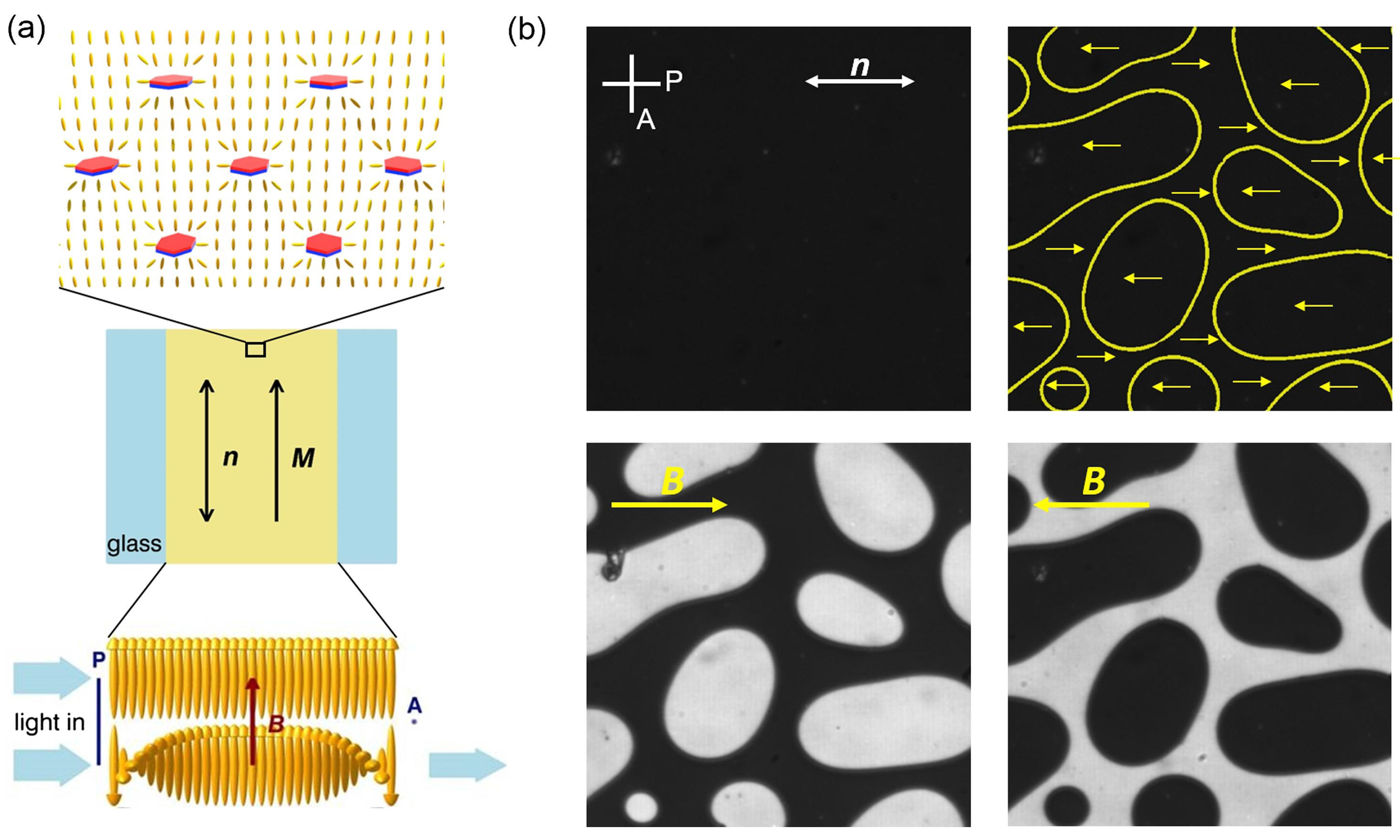
6. Functionalized Colloids: Ferromagnetic Liquid Crystal Structures

Design and different functionalization of liquid crystal agents, from molecules to colloidal-type particles, can lead to realization of different liquid crystal structures, and even new liquid crystal phases [150]. For the illustration, we chose an interesting example of a distinct type of functionalization that led to the development of ferromagnetic liquid crystal structures [20,56], either in diluted or dense suspensions, which leads to combined effects of liquid crystal ordering and ferromagnetism. Effectively, such systems perform as liquid ferromagnets.

6.1. Suspensions of Magnetic Platelets in Liquid Crystals

A ferromagentic nematic colloidal suspension was realized, as based on nanosized thin ferromagnetic colloidal platelets immersed in nematic liquid crystal [56]. The surfaces of the platelets are functionalized to impose perpendicular (homeotropic) alignment of the nematic, causing a stable nematic suspension with macroscopic spontaneous magnetization along the nematic director. Upon quenching of the suspension from the isotropic phase, the ferromagentic domains form, which can be aligned upon cooling into monodomains by applying external magnetic fields. The material is an intriguing liquid that possesses two order parameters, i.e., the nematic director and magnetization, which are mutually coupled. The aggregation of the ferromagnetic platelets is prevented by the nematic mediated elastic interactions between the platelets. More generally, this work is a demonstration of a novel multi ferroic material and contributes to the development in the general field of anisotropic magnetic nanoparticle materials [151] (Figure 10).

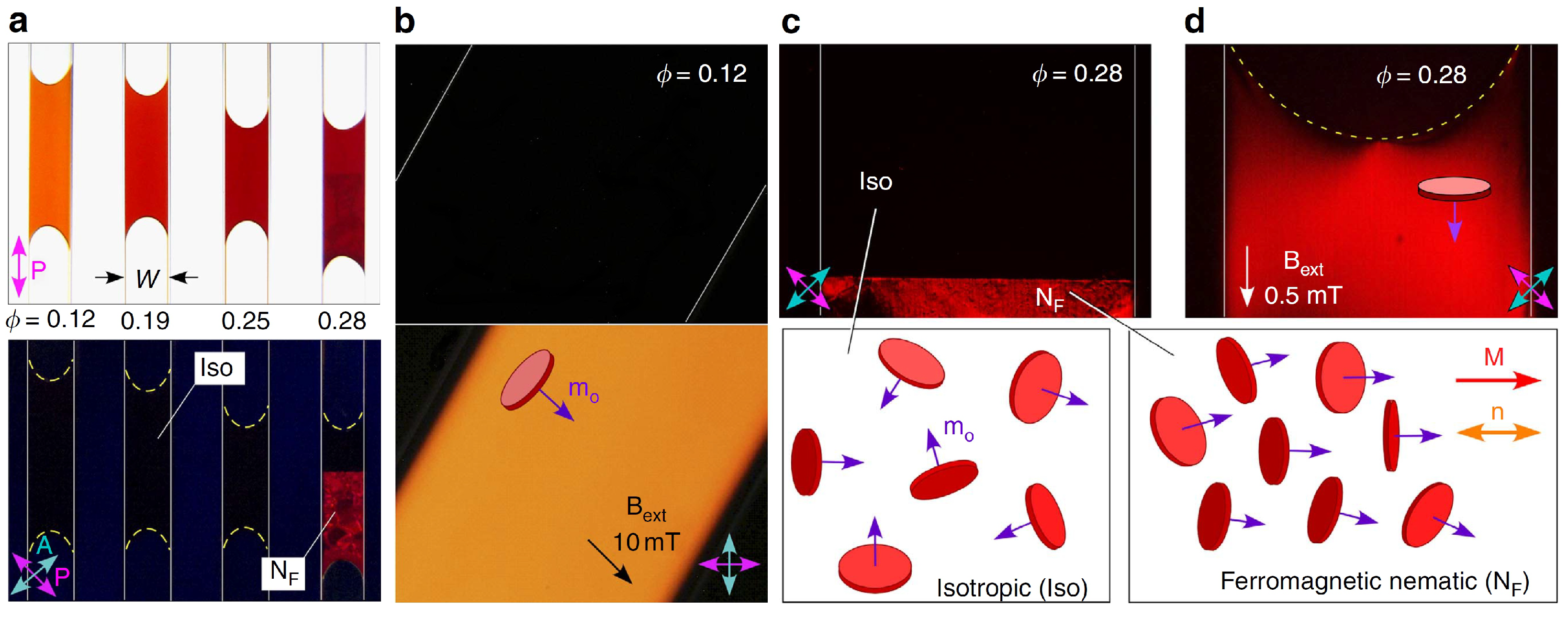
6.2. Dense Suspensions of Magnetic Platelets in Isotropic Fluids

Colloidal fluid with ferromagnetic building blocks that, at sufficiently high concentration, exhibit liquid crystal ordering (i.e., without liquid crystal host, as in Section 6.1) is realized to perform as liquid ferromagnets in the work led by N. A. Clark [20] (see Figure 11). Distinctly, ferromagnetism in colloidal fluids is achieved by creating stable, fluid suspensions of well-dispersed magnetic nanoparticles in isotropic solvent, and further designing their mutual interactions to produce equilibrium, zero-field magnetization. In the work by Clark et al, barium hexaferrite (BF) nanoplates were suspended in isotropic n-butanol and surfactant-stabilized to produce a system of functionalized nanoplates with weak electrostatic repulsion, strong and anisotropic steric repulsion, and magnetic interaction. Introducing the electrostatic repulsion prevented nanoparticle aggregation and enabled stable suspensions at essentially any concentration, importantly including at high volume fractions where spontaneous LC ordering of the platelets can emerge. The demonstrated nematic liquid crystal colloidal fluid is distinctly ferromagnetic, also forming birefringent interfacial spikes at the isotropic–nematic ferromagnet interface upon applying external magnetic field perpendicular to the interface. Finally, the realized ferromagnetic fluid produces distinctive magnetic self-interaction effects, such as fluid block domains arranged in closed flux loops, and makes this material highly sensitive, even in the Earth’s magnetic field.

7. Conclusions

Nematic fluids are characterized by the orientational order of their building blocks and include different materials, from molecular fluids and colloidal liquid crystals to viruses. The nematic orientational order is soft and responsive as an effective elastic medium to external stimuli, including mechanical fields, pressure, light, electric and magnetic fields, and dispersed colloidal particles. The strong susceptibility to external stimuli makes nematic fluids potent materials in systems that require controllability and tuneablity, which is today extensively used in display and optical applications, with strong development also towards photonics and metamaterial applications.
In this brief and selected review, we introduce three chosen directions for realizing topological liquid crystal structures: nematic colloids, nematic microfluidics, and ferromagnetic liquid crystal structures. Notably, the selection of topics is from the motivation and interest of the work from our group, but importantly as affected—directly and indirectly—by the works by Noel Clark and collaborators. All these topics fundamentally use the distinct liquid crystal ordering and its manipulation, either through the composition/structure of the actual materials or through the external fields or frustration, to produce novel material behavior or material mechanisms. This complex soft matter naturally reaches towards other fields of science and technology, notably including optics and photonics, biological and active matter, topology, microfluidics, and fluid dynamics, sensing, and metamaterials.
Finally, Noel A. Clark is one of the world pioneers who contributed and is still shaping this field of complex and functional soft matter and its applications, with his profound ingenuity and wisdom.

Funding

Authors acknowledge funding from Slovenian Research Agency (ARRS) contracts P1-0099, J1-1697, J1-2462, and N1-0195. M.R. acknowledges funding from ERC Advanced grant LOGOS.

Conflicts of Interest

The authors declare no conflict of interest.

References

  1. Frank, F.C. I. Liquid crystals. On the theory of liquid crystals. Discuss. Faraday Soc. 1958, 25, 19. [Google Scholar] [CrossRef]
  2. Maier, W.; Saupe, A. Eine einfache molekulare Theorie des nematischen kristallinflüssigen Zustandes. Z. Naturforsch. 1958, 13, 564–566. [Google Scholar] [CrossRef]
  3. Maier, W.; Saupe, A. Eine einfache molekular-statistische Theorie der nematischen kristallinflüssigen Phase. Teil I. Z. Naturforsch. 1959, 14, 882–889. [Google Scholar] [CrossRef]
  4. Maier, W.; Saupe, A. Eine einfache molekular-statistische Theorie der nematischen kristallinflüssigen Phase. Teil II. Z. Naturforsch. 1960, 15, 287–292. [Google Scholar] [CrossRef]
  5. Gennes, P.G.D. Short Range Order Effects in the Isotropic Phase of Nematics and Cholesterics. Mol. Cryst. Liq. Cryst. 1971, 12, 193. [Google Scholar] [CrossRef]
  6. Helfrich, W.; Schadt, M. Light Control Cell. Swiss Patent CH532261A, 4 December 1970. [Google Scholar]
  7. Fergason, J. Display Devices Utilizing Liquid Crystal Light Modulation. U.S. Patent US3731986A, 22 April 1971. [Google Scholar]
  8. Chen, H.; Wu, S.T. Advanced liquid crystal displays with supreme image qualities. Liq. Cryst. Today 2019, 28, 4. [Google Scholar] [CrossRef] [Green Version]
  9. Stinson, T.W.; Litster, J.D.; Clark, N.A. Static and Dynamic Behavior near the Order Disorder Transition of Nematic Liquid Crystals. J. Phys. Colloq. 1972, 33, C1–C69. [Google Scholar] [CrossRef]
  10. Young, C.Y.; Pindak, R.; Clark, N.A.; Meyer, R.B. Light-Scattering Study of Two-Dimensional Molecular-Orientation Fluctuations in a Freely Suspended Ferroelectric Liquid-Crystal Film. Phys. Rev. Lett. 1978, 40, 773. [Google Scholar] [CrossRef]
  11. Clark, N.A.; Lagerwall, S.T. Submicrosecond bistable electro-optic switching in liquid crystals. Appl. Phys. Lett. 1980, 36, 899. [Google Scholar] [CrossRef]
  12. Clark, N.A.; Lagerwall, S.T. Chiral Smectic C or H Liquid Crystal Electro-Optical Device. U.S. Patent US4367924A, 11 January 1983. [Google Scholar]
  13. Safinya, C.R.; Roux, D.; Smith, G.S.; Sinha, S.K.; Dimon, P.; Clark, N.A.; Bellocq, A.M. Steric Interactions in a Model Multimembrane System: A Synchrotron X-ray Study. Phys. Rev. Lett. 1986, 57, 2718. [Google Scholar] [CrossRef]
  14. Bellini, T.; Clark, N.; Muzny, C.; Wu, L.; Garland, C.; Schaefer, D.; Oliver, B. Phase behavior of the liquid crystal 8CB in a silica aerogel. Phys. Rev. Lett. 1992, 69, 788. [Google Scholar] [CrossRef] [PubMed]
  15. Link, D.R.; Giorgio Natale, R.S.; Maclennan, J.E.; Clark, N.A.; Körblova, E.; Walba, D.M. Spontaneous Formation of Macroscopic Chiral Domains in a Fluid Smectic Phase of Achiral Molecules. Science 1997, 278, 1924. [Google Scholar] [CrossRef] [PubMed]
  16. Kang, D.; Maclennan, J.; Clark, N.; Zakhidov, A.; Baughman, R. Electro-optic Behavior of Liquid-Crystal-Filled Silica Opal Photonic Crystals: Effect of Liquid-Crystal Alignment. Phys. Rev. Lett. 2001, 86, 4052. [Google Scholar] [CrossRef] [PubMed]
  17. Nakata, M.; Zanchetta, G.; Chapman, B.D.; Jones, C.D.; Cross, J.O.; Pindak, R.; Bellini, T.; Clark, N.A. End-to-End Stacking and Liquid Crystal Condensation of 6- to 20-Base Pair DNA Duplexes. Science 2007, 318, 1276. [Google Scholar] [CrossRef] [PubMed]
  18. Hough, L.E.; Jung, H.T.; Krüerke, D.; Heberling, M.S.; Nakata, M.; Jones, C.D.; Chen, D.; Link, D.R.; Zasadzinski, J.; Heppke, G.; et al. Helical Nanofilament Phases. Science 2009, 325, 456. [Google Scholar] [CrossRef]
  19. Chen, D.; Porada, J.H.; Hooper, J.B.; Klittnick, A.; Shen, Y.; Tuchband, M.R.; Korblova, E.; Bedrov, D.; Walba, D.M.; Glaser, M.A.; et al. Chiral heliconical ground state of nanoscale pitch in a nematic liquid crystal of achiral molecular dimers. Proc. Natl. Acad. Sci. USA 2013, 110, 15931. [Google Scholar] [CrossRef] [PubMed] [Green Version]
  20. Shuai, M.; Klittnick, A.; Shen, Y.; Smith, G.P.; Tuchband, M.R.; Zhu, C.; Petschek, R.G.; Mertelj, A.; Lisjak, D.; Čopič, M.; et al. Spontaneous liquid crystal and ferromagnetic ordering of colloidal magnetic nanoplates. Nat. Commun. 2016, 7, 10394. [Google Scholar] [CrossRef] [PubMed]
  21. Kléman, M. Defect densities in directional media, mainly liquid crystals. Philos. Mag. 1973, 27, 1057. [Google Scholar] [CrossRef]
  22. Volovik, G.E.; Mineev, V.P. Investigation of singularities in superfluid He3 in liquid crystals by the homotopic topology methods. J. Exp. Theor. Phys. 1977, 45, 1186. [Google Scholar]
  23. Mermin, N. The topological theory of defects in ordered media. Rev. Mod. Phys. 1979, 51, 591. [Google Scholar] [CrossRef]
  24. Volovik, G.; Lavrentovich, O. Topological dynamics of defects: Boojums in nematic drops. Zh. Eksp. Teor. Fiz. 1983, 85, 1159. [Google Scholar]
  25. Doane, J.W.; Vaz, N.A.; Wu, B.G.; Žumer, S. Field controlled light scattering from nematic microdroplets. Appl. Phys. Lett. 1986, 48, 269. [Google Scholar] [CrossRef]
  26. Kurik, M.V.; Lavrentovich, O.D. Defects in liquid crystals: Homotopy theory and experimental studies. Sov. Phys. Usp. 1988, 31, 196. [Google Scholar] [CrossRef]
  27. Crawford, G.; Allender, D.; Doane, J. Surface elastic and molecular-anchoring properties of nematic liquid crystals confined to cylindrical cavities. Phys. Rev. A 1992, 45, 8693. [Google Scholar] [CrossRef] [PubMed] [Green Version]
  28. Nelson, D.R. Toward a Tetravalent Chemistry of Colloids. Nano Lett. 2002, 2, 1125. [Google Scholar] [CrossRef] [Green Version]
  29. Skačej, G.; Zannoni, C. Controlling surface defect valence in colloids. Phys. Rev. Lett. 2008, 100, 197802. [Google Scholar] [CrossRef] [PubMed]
  30. Lopez-Leon, T.; Koning, V.; Devaiah, K.B.S.; Vitelli, V.; Fernandez-Nieves, A. Frustrated nematic order in spherical geometries. Nat. Phys. 2011, 7, 391. [Google Scholar] [CrossRef] [Green Version]
  31. Kralj, S.; Rosso, R.; Virga, E.G. Curvature control of valence on nematic shells. Soft Matter 2011, 7, 670. [Google Scholar] [CrossRef]
  32. Napoli, G.; Vergori, L. Extrinsic Curvature Effects on Nematic Shells. Phys. Rev. Lett. 2012, 108, 207803. [Google Scholar] [CrossRef]
  33. Terentjev, E. Disclination loops, standing alone and around solid particles, in nematic liquid crystals. Phys. Rev. E 1995, 51, 1330. [Google Scholar] [CrossRef]
  34. Poulin, P.; Stark, H.; Lubensky, T.C.; Weitz, D.A. Novel Colloidal Interactions in Anisotropic Fluids. Science 1997, 275, 1770. [Google Scholar] [CrossRef] [Green Version]
  35. Lubensky, T.C.; Pettey, D.; Currier, N.; Stark, H. Topological defects and interactions in nematic emulsions. Phys. Rev. E 1998, 57, 610. [Google Scholar] [CrossRef] [Green Version]
  36. Stark, H. Physics of colloidal dispersions in nematic liquid crystals. Phys. Rep. 2001, 351, 387. [Google Scholar] [CrossRef]
  37. Fukuda, J.; Yokoyama, H. Director configuration and dynamics of a nematic liquid crystal around a two-dimensional spherical particle: Numerical analysis using adaptive grids. Eur. Phys. J. E 2001, 4, 389. [Google Scholar] [CrossRef]
  38. Muševič, I.; Škarabot, M.; Tkalec, U.; Ravnik, M.; Žumer, S. Two-Dimensional Nematic Colloidal Crystals Self-Assembled by Topological Defects. Science 2006, 313, 954. [Google Scholar] [CrossRef] [PubMed]
  39. Ognysta, U.; Nych, A.; Nazarenko, V.; Škarabot, M.; Muševič, I. Design of 2D Binary Colloidal Crystals in a Nematic Liquid Crystal. Langmuir 2009, 25, 12092. [Google Scholar] [CrossRef] [PubMed]
  40. Nych, A.; Ognysta, U.; Škarabot, M.; Ravnik, M.; Žumer, S.; Muševič, I. Assembly and control of 3D nematic dipolar colloidal crystals. Nat. Commun. 2013, 4, 1489. [Google Scholar] [CrossRef]
  41. Luo, Y.; Serra, F.; Beller, D.A.; Gharbi, M.A.; Li, N.; Yang, S.; Kamien, R.D.; Stebe, K.J. Around the corner: Colloidal assembly and wiring in groovy nematic cells. Phys. Rev. E 2016, 93, 032705. [Google Scholar] [CrossRef] [Green Version]
  42. Ravnik, M.; Škarabot, M.; Žumer, S.; Tkalec, U.; Poberaj, I.; Babič, D.; Osterman, N.; Muševič, I. Entangled Nematic Colloidal Dimers and Wires. Phys. Rev. Lett. 2007, 99, 247801. [Google Scholar] [CrossRef] [PubMed] [Green Version]
  43. Čopar, S.; Žumer, S. Nematic Braids: Topological Invariants and Rewiring of Disclinations. Phys. Rev. Lett. 2011, 106, 177801. [Google Scholar] [CrossRef] [Green Version]
  44. Tkalec, U.; Ravnik, M.; Čopar, S.; Žumer, S.; Muševič, I. Reconfigurable Knots and Links in Chiral Nematic Colloids. Science 2011, 333, 62. [Google Scholar] [CrossRef] [Green Version]
  45. Araki, T.; Buscaglia, M.; Bellini, T.; Tanaka, H. Memory and topological frustration in nematic liquid crystals confined in porous materials. Nat. Mater. 2011, 10, 303. [Google Scholar] [CrossRef]
  46. Serra, F.; Vishnubhatla, K.C.; Buscaglia, M.; Cerbino, R.; Osellame, R.; Cerullo, G.; Bellini, T. Topological defects of nematic liquid crystals confined in porous networks. Soft Matter 2011, 7, 10945. [Google Scholar] [CrossRef]
  47. Čopar, S.; Clark, N.A.; Ravnik, M.; Žumer, S. Elementary building blocks of nematic disclination networks in densely packed 3D colloidal lattices. Soft Matter 2013, 9, 8203. [Google Scholar] [CrossRef]
  48. Lapointe, C.P.; Mason, T.G.; Smalyukh, I.I. Shape-Controlled Colloidal Interactions in Nematic Liquid Crystals. Science 2009, 326, 1083. [Google Scholar] [CrossRef] [Green Version]
  49. Dontabhaktuni, J.; Ravnik, M.; Žumer, S. Quasicrystalline tilings with nematic colloidal platelets. Proc. Natl. Acad. Sci. USA 2014, 111, 2464. [Google Scholar] [CrossRef] [Green Version]
  50. Nikkhou, M.; Škarabot, M.; Čopar, S.; Ravnik, M.; Žumer, S.; Muševič, I. Light-controlled topological charge in a nematic liquid crystal. Nat. Phys. 2015, 11, 183. [Google Scholar] [CrossRef]
  51. Mundoor, H.; Senyuk, B.; Smalyukh, I.I. Triclinic nematic colloidal crystals from competing elastic and electrostatic interactions. Science 2016, 352, 69. [Google Scholar] [CrossRef] [PubMed] [Green Version]
  52. Senyuk, B.; Liu, Q.; He, S.; Kamien, R.D.; Kusner, R.B.; Lubensky, T.C.; Smalyukh, I.I. Topological colloids. Nature 2013, 493, 200. [Google Scholar] [CrossRef] [PubMed] [Green Version]
  53. Martinez, A.; Ravnik, M.; Lucero, B.; Visvanathan, R.; Žumer, S.; Smalyukh, I.I. Mutually tangled colloidal knots and induced defect loops in nematic fields. Nat. Mater. 2014, 13, 258. [Google Scholar] [CrossRef]
  54. Ravnik, M.; Čopar, S.; Žumer, S. Particles with changeable topology in nematic colloids. J. Phys. Condens. Matter 2015, 27, 354111. [Google Scholar] [CrossRef]
  55. Yuan, Y.; Tasinkevych, M.; Smalyukh, I.I. Colloidal interactions and unusual crystallization versus de-mixing of elastic multipoles formed by gold mesoflowers. Nat. Commun. 2020, 11, 811. [Google Scholar] [CrossRef] [PubMed]
  56. Mertelj, A.; Lisjak, D.; Drofenik, M.; Čopič, M. Ferromagnetism in suspensions of magnetic platelets in liquid crystal. Nature 2013, 504, 237. [Google Scholar] [CrossRef]
  57. Ericksen, J.L. Anisotropic fluids. Arch. Ration. Mech. Anal. 1959, 4, 231. [Google Scholar] [CrossRef]
  58. Leslie, F. Theory of Flow Phenomena in Liquid Crystals. Adv. Liq. Cryst. 1979, 4, 1–81. [Google Scholar]
  59. Berreman, D.W. Liquid-crystal twist cell dynamics with backflow. J. Appl. Phys. 1975, 46, 3746. [Google Scholar] [CrossRef]
  60. Van Doorn, C.Z. Dynamic behavior of twisted nematic liquid-crystal layers in switched fields. J. Appl. Phys. 1975, 46, 3738. [Google Scholar] [CrossRef]
  61. Kramer, L.; Pesch, W. Convection Instabilities in Nematic Liquid Crystals. Annu. Rev. Fluid Mech. 1995, 27, 515. [Google Scholar] [CrossRef]
  62. Éber, N.; Salamon, P.; Buka, A. Electrically induced patterns in nematics and how to avoid them. Liq. Cryst. Rev. 2016, 4, 101. [Google Scholar] [CrossRef]
  63. Doostmohammadi, A.; Shendruk, T.N.; Thijssen, K.; Yeomans, J.M. Onset of meso-scale turbulence in active nematics. Nat. Commun. 2017, 8, 15326. [Google Scholar] [CrossRef]
  64. Sengupta, A. Topological microfluidics: Present and prospects. Liq. Cryst. Today 2015, 24, 70. [Google Scholar] [CrossRef]
  65. De Gennes, P.G.; Prost, J. Physics of Liquid Crystals; Oxford University Press: New York, NY, USA, 1993. [Google Scholar]
  66. Schiele, K.; Trimper, S. On the Elastic Constants of a Nematic Liquid Crystal. Phys. Stat. Sol. 1983, 118, 267. [Google Scholar] [CrossRef]
  67. Ravnik, M.; Žumer, S. Landau–de Gennes modelling of nematic liquid crystal colloids. Liq. Cryst. 2009, 36, 1201. [Google Scholar] [CrossRef]
  68. Sussman, D.M.; Beller, D.A. Fast, Scalable, and Interactive Software for Landau-de Gennes Numerical Modeling of Nematic Topological Defects. Front. Phys. 2019, 7, 273. [Google Scholar] [CrossRef] [Green Version]
  69. Davis, T.A.; Gartland, E.C. Finite Element Analysis of the Landau–de Gennes Minimization Problem for Liquid Crystals. SIAM J. Numer. Anal. 1998, 35, 336. [Google Scholar] [CrossRef]
  70. Everts, J.C.; Ravnik, M. Ionically Charged Topological Defects in Nematic Fluids. Phys. Rev. X 2021, 11, 011054. [Google Scholar]
  71. Nitschke, I.; Reuther, S.; Voigt, A. Liquid crystals on deformable surfaces. Proc. R. Soc. A 2020, 476, 20200313. [Google Scholar] [CrossRef]
  72. Majumdar, A.; Zarnescu, A. Landau–De Gennes Theory of Nematic Liquid Crystals: The Oseen–Frank Limit and Beyond. Arch. Ration. Mech. Anal. 2010, 196, 227. [Google Scholar] [CrossRef] [Green Version]
  73. Majumdar, A. Equilibrium order parameters of nematic liquid crystals in the Landau-de Gennes theory. Eur. J. Appl. Math. 2010, 21, 181–203. [Google Scholar] [CrossRef] [Green Version]
  74. Beris, A.N.; Edwards, B.J. Thermodynamics of Flowing Systems with Internal Microstructure; Oxford University Press: New York, NY, USA, 1994. [Google Scholar]
  75. Qian, T.; Sheng, P. Generalized hydrodynamic equations for nematic liquid crystals. Phys. Rev. E 1998, 58, 7475. [Google Scholar] [CrossRef] [Green Version]
  76. Sonnet, A.M.; Maffettone, P.L.; Virga, E.G. Continuum theory for nematic liquid crystals with tensorial order. J. Non-Newton. Fluid. 2004, 119, 51. [Google Scholar] [CrossRef]
  77. Sonnet, A.M. Dissipative Ordered Fluids: Theories for Liquid Crystals; Springer: New York, NY, USA, 2012. [Google Scholar]
  78. Denniston, C.; Orlandini, E.; Yeomans, J. Lattice {Boltzmann} simulations of liquid crystal hydrodynamics. Phys. Rev. E 2001, 63, 56702. [Google Scholar] [CrossRef] [PubMed] [Green Version]
  79. Kos, v.; Aplinc, J.; Mur, U.; Ravnik, M. Mesoscopic Approach to Nematic Fluids in Flowing Matter; Toschi, F., Sega, M., Eds.; Springer Open: Berlin, Germany, 2019. [Google Scholar]
  80. Svenšek, D.; Žumer, S. Hydrodynamics of pair-annihilating disclination lines in nematic liquid crystals. Phys. Rev. E 2002, 66, 21712. [Google Scholar] [CrossRef] [Green Version]
  81. Tóth, G.; Denniston, C.; Yeomans, J.M. Hydrodynamics of Topological Defects in Nematic Liquid Crystals. Phys. Rev. Lett. 2002, 88, 105504. [Google Scholar] [CrossRef] [PubMed] [Green Version]
  82. Sengupta, A.; Tkalec, U.; Ravnik, M.; Yeomans, J.; Bahr, C.; Herminghaus, S. Liquid Crystal Microfluidics for Tunable Flow Shaping. Phys. Rev. Lett. 2013, 110, 48303. [Google Scholar] [CrossRef] [PubMed]
  83. Denniston, C.; Marenduzzo, D.; Orlandini, E.; Yeomans, J. Lattice Boltzmann algorithm for three-dimensional liquid-crystal hydrodynamics. Phil. Trans. R. Soc. A 2004, 362, 1745. [Google Scholar] [CrossRef]
  84. Cates, M.E.; Stratford, K.; Adhikari, R.; Stansell, P.; Desplat, J.C.; Pagonabarraga, I.; Wagner, A.J. Simulating colloid hydrodynamics with lattice Boltzmann methods. J. Phys. Condens. Matter 2004, 16, S3903. [Google Scholar] [CrossRef]
  85. James, R.; Willman, E.; FernandezFernandez, F.; Day, S. Finite-element modeling of liquid-crystal hydrodynamics with a variable degree of order. IEEE Trans. Electron. Devices 2006, 53, 1575. [Google Scholar] [CrossRef]
  86. Mandal, S.; Mazza, M.G. Multiparticle collision dynamics for tensorial nematodynamics. Phys. Rev. E 2019, 99, 89. [Google Scholar] [CrossRef] [Green Version]
  87. Shendruk, T.N.; Yeomans, J.M. Multi-particle collision dynamics algorithm for nematic fluids. Soft Matter 2015, 11, 5101. [Google Scholar] [CrossRef] [Green Version]
  88. Kléman, M.; Michel, L.; Toulouse, G. Classification of topologically stable defects in ordered media. J. Phys. Lett. Paris 1977, 38, 195. [Google Scholar] [CrossRef] [Green Version]
  89. Kleman, M. Defects in liquid crystals. Rep. Prog. Phys. 1989, 52, 555. [Google Scholar] [CrossRef]
  90. Ramaswamy, S.; Nityananda, R.; Raghunathan, V.A.; Prost, J. Power-Law Forces between Particles in a Nematic. Mol. Cryst. Liq. Crys. A 1996, 288, 175. [Google Scholar] [CrossRef]
  91. Lavrentovich, O.D. Topological defects in dispersed liquid crystals, or words and worlds around liquid crystal drops. Liq. Cryst. 1998, 24, 117. [Google Scholar] [CrossRef]
  92. Seč, D.; Čopar, S.; Žumer, S. Topological zoo of free-standing knots in confined chiral nematic fluids. Nat. Commun. 2014, 5, 3057. [Google Scholar] [CrossRef]
  93. Darmon, A.; Benzaquen, M.; Čopar, S.; Dauchot, O.; Lopez-Leon, T. Topological defects in cholesteric liquid crystal shells. Soft Matter 2016, 12, 9280. [Google Scholar] [CrossRef] [Green Version]
  94. Posnjak, G.; Čopar, S.; Muševič, I. Hidden topological constellations and polyvalent charges in chiral nematic droplets. Nat. Commun. 2017, 8, 14594. [Google Scholar] [CrossRef]
  95. Pollard, J.; Posnjak, G.; Čopar, S.; Muševič, I.; Alexander, G.P. Point Defects, Topological Chirality, and Singularity Theory in Cholesteric Liquid-Crystal Droplets. Phys. Rev. X 2019, 9, 1442. [Google Scholar] [CrossRef] [Green Version]
  96. Vitelli, V.; Nelson, D. Nematic textures in spherical shells. Phys. Rev. E 2006, 74, 021711. [Google Scholar] [CrossRef] [Green Version]
  97. Lopez-Leon, T.; Fernandez-Nieves, A. Drops and shells of liquid crystal. Colloid Polym. Sci. 2011, 289, 345. [Google Scholar] [CrossRef]
  98. Zhou, Y.; Guo, A.; Zhang, R.; Armas-Perez, J.C.; Martínez-González, J.A.; Rahimi, M.; Sadati, M.; de Pablo, J.J. Mesoscale structure of chiral nematic shells. Soft Matter 2016, 12, 8983. [Google Scholar] [CrossRef] [Green Version]
  99. Urbanski, M.; Reyes, C.G.; Noh, J.; Sharma, A.; Geng, Y.; Jampani, V.S.R.; Lagerwall, J.P.F. Liquid crystals in micron-scale droplets, shells and fibers. J. Phys. Condens. Matter 2017, 29, 133003. [Google Scholar] [CrossRef] [Green Version]
  100. Tran, L.; Lavrentovich, M.O.; Durey, G.; Darmon, A.; Haase, M.F.; Li, N.; Lee, D.; Stebe, K.J.; Kamien, R.D.; Lopez-Leon, T. Change in Stripes for Cholesteric Shells via Anchoring in Moderation. Phys. Rev. X 2017, 7, 167. [Google Scholar] [CrossRef] [Green Version]
  101. Janich, K. Topological properties of ordinary nematics in 3-space. Acta Appl. Math. 1987, 8, 65. [Google Scholar] [CrossRef]
  102. Alexander, G.P.; ge Chen, B.G.; Matsumoto, E.A.; Kamien, R.D. Colloquium: Disclination loops, point defects, and all that in nematic liquid crystals. Rev. Mod. Phys. 2012, 84, 497. [Google Scholar] [CrossRef] [Green Version]
  103. Čopar, S. Topology and geometry of nematic braids. Phys. Rep. 2014, 538, 1. [Google Scholar] [CrossRef]
  104. Machon, T.; Alexander, G.P. Global defect topology in nematic liquid crystals. Proc. R. Soc. A 2016, 472, 20160265. [Google Scholar] [CrossRef] [PubMed] [Green Version]
  105. Čopar, S.; Žumer, S. Quaternions and hybrid nematic disclinations. Proc. R. Soc. A 2013, 469, 20130204. [Google Scholar] [CrossRef] [Green Version]
  106. Binysh, J.; Kos, Ž.; Čopar, S.; Ravnik, M.; Alexander, G.P. Three-Dimensional Active Defect Loops. Phys. Rev. Lett. 2020, 124, 257. [Google Scholar] [CrossRef] [PubMed] [Green Version]
  107. Beller, D.A.; Machon, T.; Čopar, S.; Sussman, D.M.; Alexander, G.P.; Kamien, R.D.; Mosna, R.A. Geometry of the Cholesteric Phase. Phys. Rev. X 2014, 4, 031050. [Google Scholar] [CrossRef] [Green Version]
  108. Poenaru, V.; Toulouse, G. The crossing of defects in ordered media and the topology of 3-manifolds. J. Phys. 1977, 38, 887. [Google Scholar] [CrossRef] [Green Version]
  109. Čopar, S.; Tkalec, U.; Muševič, I.; Žumer, S. Knot theory realizations in nematic colloids. Proc. Natl. Acad. Sci. USA 2015, 112, 1675. [Google Scholar] [CrossRef] [PubMed] [Green Version]
  110. Machon, T. The topology of knots and links in nematics. Liq. Cryst. Today 2019, 28, 58. [Google Scholar] [CrossRef] [Green Version]
  111. Araki, T.; Serra, F.; Tanaka, H. Defect science and engineering of liquid crystals under geometrical frustration. Soft Matter 2013, 9, 8107. [Google Scholar] [CrossRef] [Green Version]
  112. Sentker, K.; Yildirim, A.; Lippmann, M.; Zantop, A.W.; Bertram, F.; Hofmann, T.; Seeck, O.H.; Kityk, A.V.; Mazza, M.G.; Schönhals, A.; et al. Self-assembly of liquid crystals in nanoporous solids for adaptive photonic metamaterials. Nanoscale 2019, 11, 23304. [Google Scholar] [CrossRef]
  113. Yi, Y.; Lombardo, G.; Ashby, N.; Barberi, R.; Maclennan, J.E.; Clark, N.A. Topographic-pattern-induced homeotropic alignment of liquid crystals. Phys. Rev. E 2009, 79, 041701. [Google Scholar] [CrossRef]
  114. Carlton, R.J.; Hunter, J.T.; Miller, D.S.; Abbasi, R.; Mushenheim, P.C.; Tan, L.N.; Abbott, N.L. Chemical and biological sensing using liquid crystals. Liq. Cryst. Rev. 2013, 1, 29. [Google Scholar] [CrossRef] [PubMed]
  115. Tartan, C.C.; O’Neill, J.J.S.; Salter, P.S.; Aplinc, J.; Booth, M.J.; Ravnik, M.; Morris, S.M.; Elston, S.J. Read on Demand Images in Laser-Written Polymerizable Liquid Crystal Devices. Adv. Opt. Mater. 2018, 6, 1800515. [Google Scholar] [CrossRef] [Green Version]
  116. Kim, D.S.; Čopar, S.; Tkalec, U.; Yoon, D.K. Mosaics of topological defects in micropatterned liquid crystal textures. Sci. Adv. 2018, 4, eaau8064. [Google Scholar] [CrossRef] [Green Version]
  117. Kim, M.; Serra, F. Tunable Dynamic Topological Defect Pattern Formation in Nematic Liquid Crystals. Adv. Opt. Mater. 2020, 8, 1900991. [Google Scholar] [CrossRef]
  118. Muševič, I. Nematic colloids, topology and photonics. Phil. Trans. R. Soc. A 2013, 371, 20120266. [Google Scholar] [CrossRef] [Green Version]
  119. Tkalec, U.; Muševič, I. Topology of nematic liquid crystal colloids confined to two dimensions. Soft Matter 2013, 9, 8140. [Google Scholar] [CrossRef]
  120. Ognysta, U.; Nych, A.; Nazarenko, V.; Muševič, I.; Škarabot, M.; Ravnik, M.; Žumer, S.; Poberaj, I.; Babič, D. 2D Interactions and Binary Crystals of Dipolar and Quadrupolar Nematic Colloids. Phys. Rev. Lett. 2008, 100, 217803. [Google Scholar] [CrossRef]
  121. Škarabot, M.; Ravnik, M.; Žumer, S.; Tkalec, U.; Poberaj, I.; Babič, D.; Osterman, N.; Muševič, I. Two-dimensional dipolar nematic colloidal crystals. Phys. Rev. E 2007, 76, 51406. [Google Scholar] [CrossRef]
  122. Škarabot, M.; Ravnik, M.; Žumer, S.; Tkalec, U.; Poberaj, I.; Babič, D.; Osterman, N.; Muševič, I. Interactions of quadrupolar nematic colloids. Phys. Rev. E 2008, 77, 31705. [Google Scholar] [CrossRef] [PubMed]
  123. Bouligand, Y. Recherches sur les textures des états mésomorphes: Dislocations coins et signification des cloisons de Grandjean-Cano dans les cholestériques. J. Phys. Fr. 1974, 35, 959. [Google Scholar] [CrossRef]
  124. Tai, J.S.B.; Smalyukh, I.I. Three-dimensional crystals of adaptive knots. Science 2019, 365, 1449. [Google Scholar] [CrossRef] [PubMed] [Green Version]
  125. Jampani, V.S.R.; Škarabot, M.; Ravnik, M.; Čopar, S.; Žumer, S.; Muševič, I. Colloidal entanglement in highly twisted chiral nematic colloids: Twisted loops, Hopf links, and trefoil knots. Phys. Rev. E 2011, 84, 031703. [Google Scholar] [CrossRef]
  126. Rasi, M.M.; Pujala, R.K.; Dhara, S. Colloidal analogues of polymer chains, ribbons and 2D crystals employing orientations and interactions of nano-rods dispersed in a nematic liquid crystal. Sci. Rep. 2019, 9, 401001. [Google Scholar]
  127. Lapointe, C.P.; Hopkins, S.; Mason, T.G.; Smalyukh, I.I. Electrically Driven Multiaxis Rotational Dynamics of Colloidal Platelets in Nematic Liquid Crystals. Phys. Rev. Lett. 2010, 105, 178301. [Google Scholar] [CrossRef] [PubMed]
  128. Martinez, A.; Hermosillo, L.; Tasinkevych, M.; Smalyukh, I.I. Linked topological colloids in a nematic host. Proc. Natl. Acad. Sci. USA 2015, 112, 4546. [Google Scholar] [CrossRef] [Green Version]
  129. Lapointe, C.P.; Mayoral, K.; Mason, T.G. Star colloids in nematic liquid crystals. Soft Matter 2013, 9, 7843. [Google Scholar] [CrossRef] [Green Version]
  130. Senyuk, B.; Liu, Q.; Bililign, E.; Nystrom, P.D.; Smalyukh, I.I. Geometry-guided colloidal interactions and self-tiling of elastic dipoles formed by truncated pyramid particles in liquid crystals. Phys. Rev. E 2015, 91, 040501. [Google Scholar] [CrossRef] [PubMed] [Green Version]
  131. Senyuk, B.; Pandey, M.B.; Liu, Q.; Tasinkevych, M.; Smalyukh, I.I. Colloidal spirals in nematic liquid crystals. Soft Matter 2015, 11, 8758. [Google Scholar] [CrossRef] [PubMed] [Green Version]
  132. Sahu, D.K.; Anjali, T.G.; Basavaraj, M.G.; Aplinc, J.; Čopar, S.; Dhara, S. Orientation, elastic interaction and magnetic response of asymmetric colloids in a nematic liquid crystal. Sci. Rep. 2019, 9, 1557. [Google Scholar] [CrossRef] [PubMed]
  133. Yuan, Y.; Martinez, A.; Senyuk, B.; Tasinkevych, M.; Smalyukh, I.I. Chiral liquid crystal colloids. Nat. Mater. 2017, 17, 71. [Google Scholar] [CrossRef] [Green Version]
  134. Hashemi, S.M.; Jagodič, U.; Mozaffari, M.R.; Ejtehadi, M.R.; Muševič, I.; Ravnik, M. Fractal nematic colloids. Nat. Commun. 2017, 8, 14026. [Google Scholar] [CrossRef]
  135. Zhao, Q.; Kang, L.; Du, B.; Li, B.; Zhou, J.; Tang, H.; Liang, X.; Zhang, B. Electrically tunable negative permeability metamaterials based on nematic liquid crystals. Appl. Phys. Lett. 2007, 90, 011112. [Google Scholar] [CrossRef]
  136. Aplinc, J.; Pusovnik, A.; Ravnik, M. Designed self-assembly of metamaterial split-ring colloidal particles in nematic liquid crystals. Soft Matter 2019, 15, 5585. [Google Scholar] [CrossRef]
  137. Liu, M.; Fan, K.; Padilla, W.; Powell, D.A.; Zhang, X.; Shadrivov, I.V. Tunable Meta-Liquid Crystals. Adv. Mater. 2016, 28, 1553. [Google Scholar] [CrossRef] [Green Version]
  138. Chen, X.; Fonseca, I.; Ravnik, M.; Slastikov, V.; Zannoni, C.; Zarnescu, A. Topics in the mathematical design of materials. Phil. Trans. R. Soc. A 2021, 379, 20200108. [Google Scholar] [CrossRef] [PubMed]
  139. Gharbi, M.A.; Cavallaro, M.; Wu, G.; Beller, D.A.; Kamien, R.D.; Yang, S.; Stebe, K.J. Microbullet assembly: Interactions of oriented dipoles in confined nematic liquid crystal. Liq. Cryst. 2013, 40, 1619. [Google Scholar] [CrossRef] [Green Version]
  140. Takeuchi, K.A.; Sano, M. Universal Fluctuations of Growing Interfaces: Evidence in Turbulent Liquid Crystals. Phys. Rev. Lett. 2010, 104, 230601. [Google Scholar] [CrossRef] [PubMed] [Green Version]
  141. Wiese, O.; Marenduzzo, D.; Henrich, O. Microfluidic flow of cholesteric liquid crystals. Soft Matter 2016, 12, 9223. [Google Scholar] [CrossRef] [PubMed] [Green Version]
  142. Dogic, Z.; Fraden, S. Ordered phases of filamentous viruses. Curr. Opin. Colloid Interface Sci. 2006, 11, 47. [Google Scholar] [CrossRef]
  143. Aplinc, J.; Štimulak, M.; Čopar, S.; Ravnik, M. Nematic liquid crystal gyroids as photonic crystals. Liq. Cryst. 2016, 43, 2320. [Google Scholar] [CrossRef]
  144. Giomi, L.; Kos, Ž.; Ravnik, M.; Sengupta, A. Cross-talk between topological defects in different fields revealed by nematic microfluidics. Proc. Natl. Acad. Sci. USA 2017, 114, E5771. [Google Scholar] [CrossRef] [Green Version]
  145. Araki, T. Dynamic Coupling between a multistable Defect Pattern and Flow in Nematic Liquid Crystals Confined in a Porous Medium. Phys. Rev. Lett. 2012, 109, 257801. [Google Scholar] [CrossRef] [Green Version]
  146. Kos, Ž.; Ravnik, M.; Žumer, S. Nematodynamics and structures in junctions of cylindrical micropores. Liq. Cryst. 2017, 44, 2161–2171. [Google Scholar] [CrossRef]
  147. Sengupta, A.; Pieper, C.; Enderlein, J.; Bahr, C.; Herminghaus, S. Flow of a nematogen past a cylindrical micro-pillar. Soft Matter 2013, 9, 1937. [Google Scholar] [CrossRef]
  148. Luo, Y.; Beller, D.A.; Boniello, G.; Serra, F.; Stebe, K.J. Tunable colloid trajectories in nematic liquid crystals near wavy walls. Nat. Commun. 2018, 9, 1253751. [Google Scholar] [CrossRef] [Green Version]
  149. Čopar, S.; Kos, Ž.; Emeršič, T.; Tkalec, U. Microfluidic control over topological states in channel-confined nematic flows. Nat. Commun. 2020, 11, 977. [Google Scholar] [CrossRef]
  150. Smalyukh, I.I. Liquid Crystal Colloids. Annu. Rev. Condens. Matter Phys. 2018, 9, 207. [Google Scholar] [CrossRef]
  151. Lisjak, D.; Mertelj, A. Anisotropic magnetic nanoparticles: A review of their properties, syntheses and potential applications. Prog. Mater. Sci. 2018, 95, 286. [Google Scholar] [CrossRef]
Figure 1. Schematic representation of complex nematic structures. Orange shows continuum liquid crystal phase consisting from nematic building blocks with characteristic size a. Green indicates general confinement which can be imposed either by different surfaces, such as particles and channel or cell walls. A scheme of a topological defect is shown in black.
Crystals 11 00956 g001
Figure 2. Topological charge. (a) The simplest nematic point defects: the radial and hyperbolic hedgehog. (b) A colloidal particle with an accompanying defect, forming an elastic dipole and an elastic quadrupole. The image (b) is reprinted and adapted with permission from the reference [38]–Copyright (2006) AAAS.
Crystals 11 00956 g002
Figure 3. Topology of disclination lines. (a) Disclinations with planar cross sections with winding numbers + 1 / 2 and 1 / 2 . (b) Disclination lines with 1 / 2 can twist or writhe, accumulating self-linking Sl when closed into a loop. (c) Disclinations can be reconfigured in three different ways at possible selected rewiring sites, which can emerge in different nematic colloidal assemblies.
Crystals 11 00956 g003
Figure 4. Colloidal assemblies of spherical microparticles in a nematic under different confinement conditions. Two-dimensional crystals can be formed from (a), (b) dipolar-quadrupolar, or (c) quadrupolar particle and defect units. (d) Assembly entangled with a knotted disclination loop. (e) Three-dimensional nematic colloidal crystal assembled with laser tweezers, with (right) a 3D confocal image. The images are reprinted and adapted with permission from the references: (a) [121]–Copyritht (2007) APS, (b) [39]–Copyright (2008) APS, (c) [122]–Copyright (2008) APS, (d) [109]–Copyright (2015) National Academy of Sciences, (e) [40]–Copyright (2013) Springer Nature.
Crystals 11 00956 g004
Figure 5. Knotted and linked disclinations in cholesterics and nematics. (a) Transient linked cholesteric disclinations, observed by Yves Bouligand. (b) A stable knotted cholesteric disclination, by Tai et al. (c,d) Linked and knotted disclinations stabilized by silica microspheres in a π -twisted cell. (e) A complex link stabilized in a π / 2 -cell on a nematic 2D colloidal crystal grid. The images are reprinted and adapted with permission from the references: (a) [123]–Copyright (1974) EDP Sciences, (b) [124]–Copyright (2019) AAAS, (c,d) [125]–Copyright (2011) APS. (e) [109]–Copyright (2015) National Academy of Sciences.
Crystals 11 00956 g005
Figure 6. Nematic colloids with different particle shapes. Structures show different assembly characteristics, mediated by both the defects and the elastic deformation of the director field. Geometry and topology of the particles play a strong role in the behavior of the nematic host and can be tuned to achieve desired goals. Images are reprinted and adapted with permission from the references: (a) [139]–Copyright (2010) National Academy of Sciences, (b) [129]–Copyright (2013) Springer Nature, (c) [133]–Copyright (2013) Taylor & Francis, (d) [53]–Copyright (2009) AAAS, (e) [128]–Copyright (2019) Springer Nature, (f) [52]–Copyright (2017) Springer Nature, (g) [126]–Copyright (2014) Springer Nature.
Crystals 11 00956 g006
Figure 7. Porous nematic microfluidics as generator for umbilic defect lattice structures. Porous microchannels with cylindrical barriers are arranged into (a,b) triangular, (c) square, and (d) hexagonal lattices, creating: (a) a triangular lattice of + 1 umbilics and a rectangular lattice of 1 umbilics form, (b) a hexagonal lattice of + 1 umbilics and a Kagome lattice of 1 umbilics, (c) a square lattice of both + 1 and 1 umbilics, and (d) a triangular lattice of + 1 umbilics and Kagome lattice of 1 umbilic. The bottom panels show generalization of the observed structures. (e) Generation of umbilic defects of variable (high) umbilic strength by flow peaks and flow saddle points. A local peak in the velocity field generates a +umbilic, and flow saddle generates a −umbilic. The image is reprinted and adapted with permission from the reference [143]–Copyright (2016) Taylor & Francis.
Crystals 11 00956 g007
Figure 8. Flow stabilized structures in junctions of nematic-filled channels. Defect dynamics are shown in a junction with extensile flow (i.e., two outlet channels indicated by two blue arrows, and four inlet channels). Initial director profile has 2 outward escaping profiles and 4 inward escaping equilibrium configurations with a 1 defect at the channel junction center. Flow direction in top and bottom channels is aligned with the direction of director escape. As the nematic undergoes a flow-aligning transition in the left and right channel, a pair of + 1 defects is created at open channel boundaries. The pair coalesces with the previously residing 1 defect, forming a + 1 defect and, thus, preserving the bulk topological charge. Similarly, undergoing a flow alignment transition, 1 defects are created in the up and in the down channel. The defects interact and form a stationary state, consisting of a single 1 bulk defect, which is displaced from the center of the junction in the direction of one of the outgoing flows. Time is measured in units of nematic characteristic time scale τ N = ξ N 2 Γ L . The image is reprinted and adapted with permission from the reference [146]–Copyright (2016) Taylor & Francis.
Crystals 11 00956 g008
Figure 9. Nematic flow past a cylindrical barrier in nematic microchannel. (A) Morphological evolution of the defect structures in the presence of flow. Defects are drawn in red; black lines show the corresponding director. (B) Extension of the singular loop (measured between the pillar center and the leading end of the defect) shows a non-linear dependence with the Ericksen number Er. Insets show extension of the semi-integer defect loop with increasing the flow speed, observed between crossed-polarizers. Scale bar: 50 mm. (C) Time sequence of polarized micrographs representing the flow-alignment of the nematic director in microchannel. A distinct birefringent domain (green in appearance) with a parabolic boundary is observed upstream of the micro-pillar. The image is reprinted and adapted with permission from the reference [147]–Copyright (2013) RSC.
Crystals 11 00956 g009
Figure 10. Ferromagnetic suspension of Ba hexaferrite nanoplates in NLC: (a) Magnetic nanoplates (red and blue) orient with their magnetic moments along the average order of liquid-crystal molecules (yellow ellipsoids). (b) Polarized-light microscopy images of two types of antiparallel magnetic domains form with the magnetization along the NLC orientation (denoted by n). P and A indicate the orientation of the polarizer and analyzer, respectively. The upper images show the suspension in the absence of the field; in the right-hand side image, the domain walls are drawn. The bottom images show the response of the domains to a magnetic field. The image is reprinted and adapted with permission from the reference [151]–Copyright (2018) Elsevier B.V.
Crystals 11 00956 g010
Figure 11. Nematic ferrofluid from suspension of barium ferrite nanoplatelets in n-butanol. (a) Nanoplatelet suspensions viewed in transmitted light with optical polarization conditions indicated (Polarizer: magenta, P; analyzer: cyan, A). Low-volume fraction suspensions are isotropic (Iso), appearing dark between crossed polarizers. The orange/red color is due to optical absorption by the nanoplatelets. At higher concentrations ( ϕ 0.28 ), a birefringent ferromagnetic nematic (NF) phase appears in the lower part of the cell. (b) An applied in-plane magnetic field induces birefringence in the isotropic phase, with the principal axes of the optical dielectric tensor along and normal to external magnetic field and the induced macroscopic magnetization density parallel to external magnetic field. (c) The NF phase is separated gravitationally from the isotropic region by a sharp, horizontal interface. Equilibrium Iso and NF structures deduced from birefringence and dichroism measurements are illustrated. (d) The Iso phase is magnetized, and the Iso–NF interface becomes continuous, under applied magnetic field. Samples are sealed in rectangular glass capillaries. The boundaries of the cells are indicated by the solid thin white lines, and the air–liquid interfaces are indicated by the dashed yellow lines. The image is reprinted and adapted with permission from the reference [20]–Copyright (2016) Springer Nature.
Crystals 11 00956 g011
Publisher’s Note: MDPI stays neutral with regard to jurisdictional claims in published maps and institutional affiliations.

