Article

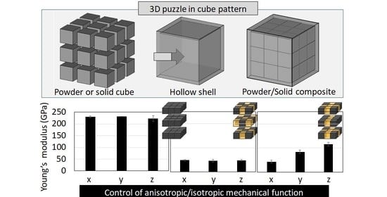
3D Puzzle in Cube Pattern for Anisotropic/Isotropic Mechanical Control of Structure Fabricated by Metal Additive Manufacturing

1
Department of Mechanical Engineering, Kobe University, 1-1 Rokkodaicho, Nada-ku, Kobe 657-8501, Japan
2
Electronic Mechanical Engineering Department, National Institute of Technology, Yuge College, 1000, Shimoyuge, Yuge, Kamijima, Ochi 794-2593, Japan
3
Division of Materials and Manufacturing Science, Graduate School of Engineering, Osaka University, Suita 565-0871, Japan
4
Department of Materials Science and Engineering, Shibaura Institute of Technology, Toyosu, Koto-ku, Tokyo 135-8548, Japan
*
Authors to whom correspondence should be addressed.
These authors contributed equally to this work.
Crystals 2021, 11(8), 959; https://doi.org/10.3390/cryst11080959
Submission received: 21 July 2021 / Revised: 10 August 2021 / Accepted: 13 August 2021 / Published: 16 August 2021

Abstract

:
Metal additive manufacturing is a powerful tool for providing the desired functional performance through a three-dimensional (3D) structural design. Among the material functions, anisotropic mechanical properties are indispensable for enabling the capabilities of structural materials for living tissues. For biomedical materials to replace bone function, it is necessary to provide an anisotropic mechanical property that mimics that of bones. For desired control of the mechanical performance of the materials, we propose a novel 3D puzzle structure with cube-shaped parts comprising 27 (3 × 3 × 3) unit compartments. We designed and fabricated a Co–Cr–Mo composite structure through spatial control of the positional arrangement of powder/solid parts using the laser powder bed fusion (L-PBF) method. The mechanical function of the fabricated structure can be predicted using the rule of mixtures based on the arrangement pattern of each part. The solid parts in the cubic structure were obtained by melting and solidifying the metal powder with a laser, while the powder parts were obtained through the remaining nonmelted powders inside the structure. This is the first report to achieve an innovative material design that can provide an anisotropic Young’s modulus by arranging the powder and solid parts using additive manufacturing technology.

Graphical Abstract

1. Introduction

Additive manufacturing technology enables the design and fabrication for realizing the desired material functions. Anisotropy is one of the most important concepts in material design because many of the structures in nature, including living bones, represent direction-dependent functional properties derived from their structural anisotropy [1,2,3,4]. However, many artificial structures are frequently utilized for isotropic mechanical functions to increase the safety factor [5,6]. This approach is based on the concept that they should have mechanical functions that can endure multiple directional purposes. In the field of orthopedics—particularly when a bone replacement device is implanted in a living bone—the mismatch in the mechanical properties (e.g., Young’s modulus) between the implant materials and the bone tissue triggers serious problems, including bone resorption and bone quality deterioration, which can result in the loosening of artificial joints [7,8,9]. The design and development of bone-mimetic functional materials that match the anisotropic structure of living tissues facilitate proper bone affinity with excellent initial fixation [10,11].
Furthermore, the useful life of artificial joints is considered to be 15–20 years, although there are individual differences depending on the patient’s age and level of activity [12]. A long period of use implies the increased potential for complications, including inconsistency between the shapes of the artificial joint and the living bone, loosening due to the difference in the mechanical functions, and surgical site infection. If the pain is severe, revision surgery is required, which is difficult and places a greater burden on patients in terms of bleeding and infection than the initial artificial joint replacement. To solve such problems, there is an urgent need to create bone implant materials that allow for customization of the shape and mechanical functions for each patient. In particular, the development of biomaterials that can mimic the anisotropic structure of living bone tissues and maximize biological functions is crucial. Recent advances in additive manufacturing technology enabled the design and fabrication of a bone-mimetic, open-porous structure, including lattice [13,14,15] and gyroid structure [16,17]. These studies demonstrate that the porous structures successfully reduce the Young’s modulus, which allows superior biomechanical compatibility; it still should be realized to control the mechanical functionalization in the desired direction with the required value.
In recent years, bone implants have been developed with a focus on shape customization [18], including material surface treatment [19,20,21,22,23]. More importantly, it is necessary to customize the mechanical function and shape in accordance with the individual patient and the implantation site. The objective of this study was to create a novel material design for realizing the desired mechanical function in the required direction, which has not yet been fully established even in recent orthopedic treatment. We devised a composite structure, consisting of powder and solid parts, that enables a mechanical function design based on structural parameters. Each element of the structure exhibits a specific mechanical function. This characteristic leads to the entire control of the mechanical properties of the fabricated structure by controlling the laser powder bed fusion (L-PBF) process.

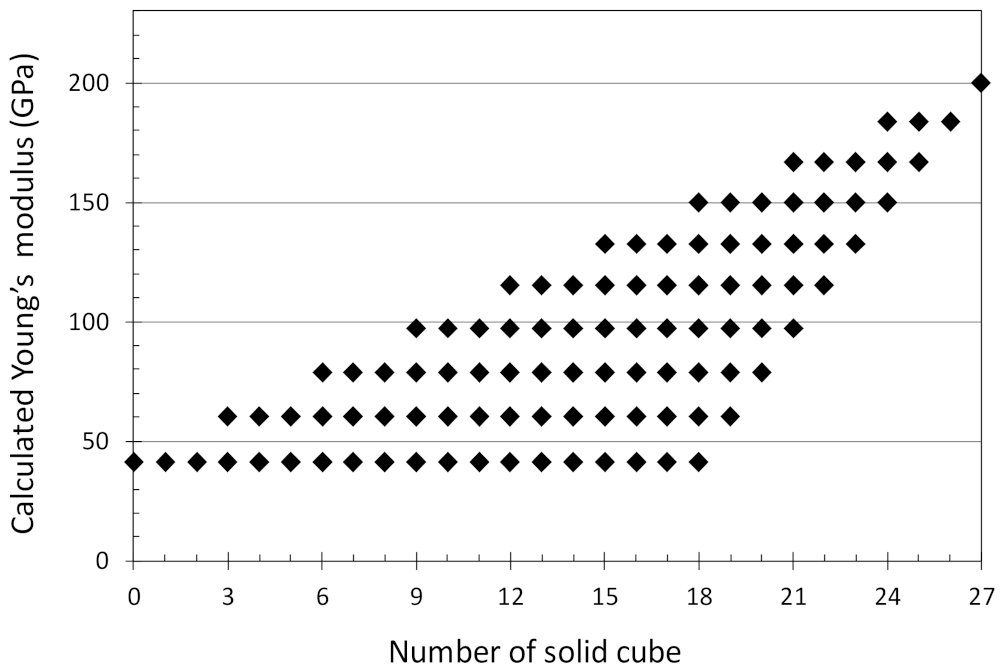
2. Mathematical Model

To express the isotropic or anisotropic mechanical functions, structural models consisting of an internal structure that included 27 cubic elements (3 × 3 × 3 arrangement) were fabricated, as shown in Figure 1. Each internal cubic structure was designed with the length of each side at 3 mm surrounded by the outer wall, which had a thickness of 0.5 mm. The three orthogonal sides of the structure are the x, y, and z axes.
The structure can be divided into multiple triplicated elements (series elements) parallel to the load axis. A series element deforms independently without interfering with the other series elements when the load is applied to the structure. The Young’s modulus of each series element is mathematically calculated using the Reuss model [24], which is a rule of mixtures in series, as expressed in Equation (1).
E series ,   j = 1 i ( V i E i )
In Equation (1), Eseries, j represents the Young’s modulus of the entire series element in the load direction, Ei denotes the Young’s modulus of each cubic element, and Vi represents the volume fraction of each microcube element with respect to the entire series element. A series element is deformed independently of the other series elements. The volume fraction of the entire structure in which all series elements are combined in parallel is mathematically calculated by the Voigt model [25], which is a rule of mixtures in parallel, as expressed in Equation (2). The calculated results of the Young’s modulus for all variants, depending on the selective positioning of powder or solid elements, are shown in Figure 2.
E composite = j E series ,   j V series ,   j
where Ecomposite is the Young’s modulus for the entire structure in the load direction, and Vseries, j is the volume fraction of each series element with respect to the entire structure.
Based on the physical properties of the Co–Cr–Mo alloy comprising this structure, the Young’s moduli of the solid and powder parts were set to 200 GPa and 0.01 GPa, respectively, according to the material data sheet which provides the mechanical properties for parts built using EOS Cobalt Chrome MP1 powder (EOS art. No. 9011-0012). The latter was sufficiently smaller than the Young’s modulus of the solid part, indicating that most of the load was applied to the solid part. The structure with a solid cube number of 0 shows the lowest Young’s modulus of 40 GPa, which is derived from the structure of the wall parts.

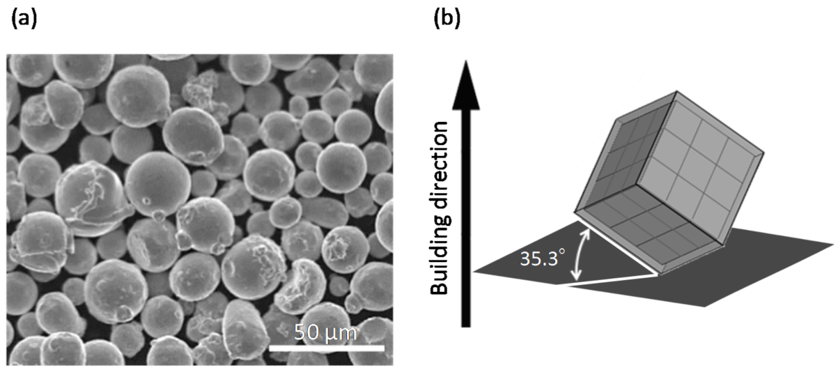
3. Materials and Methods

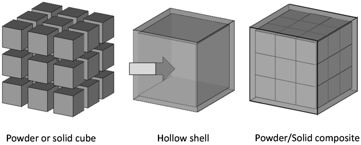
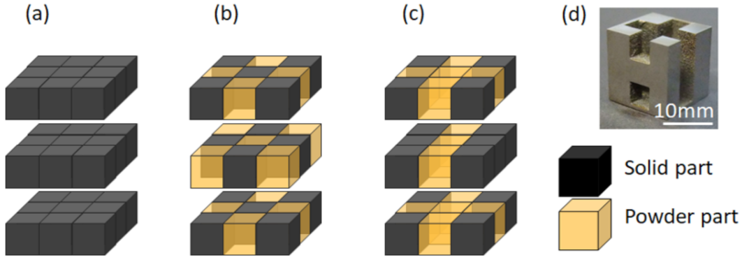
3.1. Designing the Powder/Solid Composite Structure

The raw material was a gas-atomized Co–Cr–Mo alloy powder (EOS Cobalt Chrome MP1, EOS) (Figure 3a) with the chemical composition listed in Table 1. The structure was fabricated using the L-PBF method (EOSINT M280, EOS), with a laser output of 195 W, a laser scanning speed of 800 mm s−1, a laser scanning width of 80 μm, and layer thickness of 40 μm. The crystallographic texture of the fabricated structure changes depending on the thermal gradient affected by the scanning strategy during the L-PBF process. To avoid the effects of texture on the mechanical function of the structure, the building direction was set so that the diagonal of the cube was vertical (Figure 3b), which allowed for equivalence in the three axes (x–y–z axes) along the three orthogonal sides of the structure. In addition, to eliminate the anisotropy of the heat flow due to the laser scanning direction, the scanning direction was rotated by 66° for each layer. Three types of models (i.e., all-solid, face-centered cubic (FCC), and H-shaped) were designed (Figure 4). The density of the obtained structure was measured using the Archimedes method.

3.2. Mechanical Test

The mechanical function was tested for the cube-shaped, as-built material [26,27]. An analysis was conducted with a compression test using a uniaxial mechanical testing machine (AG-X, Shimadzu, Kyoto, Japan) under the conditions of an initial strain rate of 0.01 min−1 and a measurement interval of 0.01 s. For the measurement of Young’s modulus, precision strain measurements were performed using a strain gauge (KFG-4N-120-C1-11L1M2R, Kyowa Electric, Tokyo, Japan), a sensor interface (PCD-300B, Kyowa Electric), and data acquisition software (DCS100A, Kyowa Electric, Tokyo, Japan). The sample surface was mechanically polished using #400 emery paper to keep a steady adhesion with a strain gauge. The dimensions of each axis had an in-plane error of ±5 μm. The above strain gauge was attached to four surfaces of a sample, excluding the compression surface, using a strain gauge adhesive (CC-33A, Kyowa Electric, Tokyo, Japan). The loading/unloading was repeated six times up to 65% of the assumed proof stress, which is calculated by the law of mixture in which the proof stress of the solid structure was set at 500 MPa. The Young’s modulus was analyzed from the slope in the stress range of 40–60% of the proof stress in the obtained stress–strain curve, and the results of the second to sixth analyses were taken as the average Young’s modulus.

3.3. Crystallographic Texture Analysis

Electron backscatter diffraction (EBSD) was used for microstructure observation and texture analysis. After the mechanical polishing of the observation surface with #400, #800, #1000, and #2000 emery papers, it was electropolished in an electrolytic polishing solution (10% H2SO4 + 90% CH3OH solution) at −20 °C and 13 V for 3.5 min. Subsequently, the specimens were washed with water and ethanol. After sufficient drying, the samples were observed using an EBSD analyzer attached to a field-emission scanning electron microscope (JSM-6500F, JEOL, Tokyo, Japan).

4. Results

Figure 5a shows a pole figure of γ {001} with the building direction in the center. γ {001} is oriented in the building direction, whereas no preferential texture formation is observed with a rotated crystal texture formed around the building direction. The obtained {001} orientation in the building direction implies that the textures on the three orthogonal axes (x–y–z axes) of the structure are equivalent, and anisotropy of the mechanical function along the three axes due to the material parameters is not expected. Moreover, the grain growth along the building direction is observed, which means the initial crystal orientation along the building direction affects the texture stability of the structure. In this study, the building direction was set as equivalent to the three axes to avoid the effects of texture formation as shown in Figure 3b.
The density of the fabricated all-solid model is 99.52%, indicating that the L-PBF process was well controlled to obtain a highly dense structure. Figure 6 demonstrates the stress–strain curves. Considering the equivalency among the three axes, the deformation behavior in the x-axis is shown as a representative value in the all-solid and FCC models. The plastic deformation and fracture progress depends on the existence of a column structure. Moreover, a characteristic plateau region was observed in the FCC model. The longitudinal Young’s modulus of the structure can be calculated through the rule of mixtures in the arrangement of the solid parts, and it has a certain discrete value regardless of the number of solid parts (Figure 2). Structures having the same longitudinal Young’s modulus indicates that they have the same number of series elements of solid parts parallel to the load direction. The longitudinal Young’s modulus increases in proportion to the number of such series elements. Importantly, from the results of the rule of mixtures calculation, the longitudinal Young’s modulus of the structure is determined by the number of series elements (i.e., series elements that act as a “column” in the structure) parallel to the load axis. Indeed, Young’s modulus changes significantly depending on the presence or absence of a column structure in which all series elements with dense bodies are connected in the load axis direction (Figure 7). In the H-type model, the expression of triaxial anisotropy can be controlled, whereas Young’s moduli along the x-, y-, and z-axes in the all-solid and FCC structures are equivalent. This is an important achievement that introduces a guideline for material design that can achieve the desired isotropy or anisotropy in the required direction.

5. Discussion

In the L-PBF process, the nonmelted powder remaining around the built structure and inside the porous structure is generally removed through blasting using the same raw metal powder. The removed powder can be reused as a raw metal powder for the additive manufacturing process after eliminating the impurities through sieving. However, as the pore size of a porous structure decreases and the pore shape becomes more complex, it becomes extremely difficult to remove the nonmelted powder inside the pores [28,29]. Here, we propose a novel powder/solid cube composite by positively enclosing the nonmelted powder inside the structure, which is conventionally removed.
The number of combinations of the arrangements of the powder and solid parts in the designed powder/solid composite structure can be calculated using Equation (3). In the equation, C represents the formula for combination, and n is the maximum number in which the solid part can be arranged by setting the structure in three respective directions.
i n C n i = i = 0 27 C 27 i
In the structure generated in this study, n = 27. The total number of combinations of the powder and solid arrangements, calculated using Equation (3), shows more than 100 million patterns. Regardless of the above numerous powder/solid positional patterns, the variation in the Young’s moduli of the powder/solid composite structure calculated through the mathematical model is only 10 (Figure 2). The structure with the lowest Young’s modulus, with zero solid parts, corresponds to the hollow shell structure. Because the Young’s modulus of the powder part is significantly lower than that of the solid part and has almost no load-bearing function, the load can be regarded as being supported by the side wall of the structure in the hollow shell part. Therefore, even if the number of solid parts increases, Young’s modulus does not increase when there is no columnar structure to support the load. Moreover, it is considered that, for structures in which the modulus is equivalent to that of the hollow shell part—for example, the face-centered cubic (FCC) model—the wall parts support most of the load. Additionally, the unconnected solid cube parts do not contribute to the load support because they cannot work as a column. On the other hand, the three solid parts arranged in series play the role of a column in the fabricated structure and significantly contribute to the load support. From these facts, it can be concluded that the controlling factors for Young’s modulus in the powder/solid composite structure are the number of columns in which the three solid parts are arranged in a series. From the above, Young’s modulus of the powder/solid composite structure can be predicted by the arrangement pattern of the solid and powder parts using the rule of mixtures.
The Young’s modulus in experimental results was consistent with the calculated values (Figure 7). The obtained H model realizes the triaxial anisotropy, which corresponds well with the calculated values. Young’s modulus of the obtained all-solid structure in experiments is slightly higher than the calculated value (200 GPa), which is possibly derived from the crystallographic texture in the specimens, whereas the texture is controlled as equivalent among the three axes. Moreover, the line of contact between the solid parts can cause a stress concentration, which results in the raised Young’s modulus of the puzzle structure rather than the calculated value. For example, the cube units are connected by edges with each other in the FCC model. Although this connection by edges was not taken into consideration in the calculation of Young’s modulus in this study, L-PBF fabrication with high accuracy would enable control of the edge connection. A highly precise calculation model considering the edge connection parts should be established, which would further realize the anisotropic/isotropic structural design in a more desirable way. In the experimental results, a characteristic plateau region was observed in the stress–strain curve for the FCC model, indicating the line of contact between the positioned solid cubes working as mechanical support [30]. In addition, necking formation between powder particles by heat treatment can contribute to large energy absorption [31]. The post-processing treatment for necking the particles also contributes to suppression of the cytotoxicity of the materials by preventing the flow of the metal powders away from the devices [32]. The further functionalization of the structure using the above treatment method will be reported in our future report.
Importantly, the proposed powder/solid complex can reduce Young’s modulus and realize the anisotropic/isotropic mechanical function, including yield strength, with a similar value to that in cortical bone by controlling the positional arrangement of the powder and the solid cubes [14]. The difference in the Young’s moduli of a bone and a metal material is a problem in the orthopedic field that causes stress shielding and the loosening of implants. The introduction of β phase to realize a lower Young’s modulus has been studied [33,34]. In addition, using the L-PBF process, it is possible to reduce the Young’s modulus of the metal material by controlling the material parameters (i.e., atomic arrangement), which can be realized by modulating the scanning strategy [35,36,37,38]. Simultaneous control of the hierarchical structure of the outer shape and internal structure is expected [31,39] to enable selective control of the physical properties of the metal materials to adjust them to the desired application. A three-dimensional porous model with controlled pore size and porosity was produced through additive manufacturing technology, and the connected porous structures have advantages to induce bone ingrowth [40,41,42]. Numerous important studies of lattice structure have shown the introduction of a porous structure is one of the more powerful strategies for minimizing Young’s modulus of materials, as well as anisotropic mechanical functions [15,41]. Herein, a novel puzzle structure with the required combination of solid and powder parts was proposed, which can establish a highly customized design for personal medical devices. The present model can realize the wide-range control of mechanical property with the combination of solid cube positioning, whereas the value of Young’s modulus is much more finely controllable by setting the structure design as multiple units more than 3 × 3 × 3. Further multiscale morphological control, including the outer shape and the internal positioning of the powder/solid part, can realize the desired multiple functionalities.

6. Conclusions

We succeeded in controlling the anisotropic/isotropic mechanical function of a structure based on the arrangement pattern of its powder and solid parts. This innovative method can provide the desired mechanical properties simply by controlling the structural parameters, similar to a 3D puzzle. The composite structural design proposed herein can customize the mechanical function represented by Young’s modulus and its anisotropy. These findings lead to the excellent customizability of the mechanical functions of a medical device with required mechanical properties, depending on each patient’s profile, including body shape, implantation site, and medical history.

Author Contributions

Conceptualization, T.N.; methodology, N.I., H.F. and T.N.; validation, N.I., H.F., A.S. and T.N.; formal analysis, N.I., H.F., O.G., T.I. (Takuya Ishimoto) and T.I. (Toru Inoue); investigation, N.I., H.F., A.S., T.I. (Takuya Ishimoto) and T.I. (Toru Inoue); data curation, N.I., H.F. and T.I. (Takuya Ishimoto); writing—original draft preparation, N.I., H.F. and A.M.; writing—review and editing, T.I. (Takuya Ishimoto) and T.N.; visualization, N.I., H.F., T.M., A.M., R.O. and O.G.; supervision, T.N.; project administration, T.N.; funding acquisition, T.N. All authors have read and agreed to the published version of the manuscript.

Funding

This study was supported by Grants-in-Aid for Scientific Research (grant number 18H05254) from the Japan Society for the Promotion of Science. This work was also partly supported by the Cross-Ministerial Strategic Innovation Promotion Program (SIP), Materials Integration for Revolutionary Design System of Structural Materials, Domain C1: “Development of Additive Manufacturing Process for Ni-based Alloy” from the Japan Science and Technology Agency (JST).

Data Availability Statement

The data presented in this study are available on request from the corresponding author.

Conflicts of Interest

The authors declare no conflict of interest.

References

  1. Liu, Z.; Zhang, Z.; Ritchie, R.O. Structural orientation and anisotropy in biological materials: Functional designs and mechanics. Adv. Funct. Mater. 2020, 30, 1908121. [Google Scholar] [CrossRef]
  2. Nakano, T.; Kaibara, K.; Tabata, Y.; Nagata, N.; Enomoto, S.; Marukawa, E.; Umakoshi, Y. Unique alignment and texture of biological apatite crystallites in typical calcified tissues analyzed by micro-beam X-ray diffractometer system. Bone 2002, 31, 479–487. [Google Scholar] [CrossRef]
  3. Nakano, T.; Kaibara, K.; Ishimoto, T.; Tabata, Y.; Umakoshi, Y. Biological apatite (BAp) crystallographic orientation and texture as a new index for assessing the microstructure and function of bone regenerated by tissue engineering. Bone 2012, 51, 741–747. [Google Scholar] [CrossRef]
  4. Tanaka, M.; Matsugaki, A.; Ishimoto, T.; Nakano, T. Evaluation of crystallographic orientation of biological apatite at vertebral cortical bone in ovariectomized cynomolgus monkey treated with minodronic acid and alendronate. J. Bone Miner. Metab. 2016, 34, 234–241. [Google Scholar] [CrossRef]
  5. Ding, H.; Chen, W.; Zhang, L. Solid Mechanics and Its Applications, Elasticity of Transversely Isotropic Material; Springer: Berlin/Heidelberg, Germany, 2006; pp. 29–67. [Google Scholar]
  6. Maute, K.; Allen, M. Conceptual design of aeroelastic structures by topology optimization. Struct. Multidiscip. Opt. 2004, 27, 27–42. [Google Scholar] [CrossRef]
  7. Li, C.; Granger, C.; Schutte, H.D., Jr.; Biggers, S.B., Jr.; Kennedy, J.M.; Latour, R.A., Jr. Progressive failure analysis of laminated composite femoral prostheses for total hip arthroplasty. Biomaterials 2002, 23, 4249–4262. [Google Scholar] [CrossRef]
  8. Cheal, E.; Spector, M.; Hayes, W. Role of loads and prosthesis material properties on the mechanics of the proximal femur after total hip arthroplasty. J. Orthop. Res. 1992, 10, 405–422. [Google Scholar] [CrossRef]
  9. Noyama, Y.; Miura, T.; Ishimoto, T.; Itaya, T.; Niinomi, M.; Nakano, T. Bone loss and reduced bone quality of the human femur after total hip arthroplasty under stress-shielding effects by titanium-based implant. Mater. Trans. 2012, 53, 565–570. [Google Scholar] [CrossRef] [Green Version]
  10. Ishimoto, T.; Yamada, K.; Takahashi, H.; Takahata, M.; Ito, M.; Hanawa, T.; Nakano, T. Trabecular health of vertebrae based on anisotropy in trabecular architecture and collagen/apatite micro-arrangement after implantation of intervertebral fusion cages in the sheep spine. Bone 2018, 108, 25–33. [Google Scholar] [CrossRef] [PubMed]
  11. Noyama, Y.; Nakano, T.; Ishimoto, T.; Sakai, T.; Yoshikawa, H. Design and optimization of the oriented groove on the hip implant surface to promote bone microstructure integrity. Bone 2013, 52, 659–667. [Google Scholar] [CrossRef] [PubMed]
  12. Loth, F.L.; Liebensteiner, M.C.; Giesinger, J.M.; Giesinger, K.; Bliem, H.R.; Holzner, B. What makes patients aware of their artificial knee joint? BMC Musculoskelet. Disord. 2018, 19, 5. [Google Scholar] [CrossRef] [Green Version]
  13. Soro, N.; Saintier, N.; Merzeau, J.; Veidt, M.; Dargusch, M.S. Quasi-static and fatigue properties of graded Ti–6Al–4V lattices produced by Laser Powder Bed Fusion (LPBF). Addit. Manuf. 2021, 37, 101653. [Google Scholar]
  14. Wang, P.; Li, X.; Jiang, Y.; Ling, M.; Nai, S.; Ding, J.; Wei, J. Electron beam melted heterogeneously porous microlattices for metallic bone applications: Design and investigations of boundary and edge effects. Addit. Manuf. 2020, 36, 101566. [Google Scholar] [CrossRef]
  15. Yuan, L.; Ding, S.; Wen, C. Additive manufacturing technology for porous metal implant applications and triple minimal surface structures: A review. Bioact. Mater. 2019, 4, 56–70. [Google Scholar] [CrossRef]
  16. Bobbert, F.S.L.; Lietaert, K.; Eftekhari, A.A.; Pouran, B.; Ahmadi, S.M.; Weinans, H.; Zadpoor, A.A. Additively manufactured metallic porous biomaterials based on minimal surfaces: A unique combination of topological, mechanical, and mass transport properties. Acta Biomater. 2017, 53, 572–584. [Google Scholar] [CrossRef] [Green Version]
  17. Wang, P.; Li, X.; Luo, S.; Ling, M.; Nai, S.; Ding, J.; Wei, J. Additively manufactured heterogeneously porous metallic bone with biostructural functions and bone-like mechanical properties. J. Mater. Sci. Technol. 2021, 62, 173–179. [Google Scholar] [CrossRef]
  18. Durand-Hill, M.; Henckel, J.; Laura, A.D.; Hart, A.J. Can custom 3D printed implants successfully reconstruct massive acetabular defects? A 3D-CT assessment. J. Orthop. Res. 2020, 38, 2640–2648. [Google Scholar] [CrossRef] [PubMed]
  19. Sugino, A.; Ohtsuki, C.; Tsuru, K.; Hayakawa, S.; Nakano, T.; Okazaki, Y.; Osaka, A. Effect of spatial design and thermal oxidation on apatite formation on Ti-15Zr-4Ta-4Nb alloy. Acta Biomater. 2008, 5, 298–304. [Google Scholar] [CrossRef] [PubMed]
  20. Matsugaki, A.; Aramoto, G.; Nakano, T. The alignment of MC3T3-E1 osteoblasts on steps of slip traces introduced by dislocation motion. Biomaterials 2012, 33, 7327–7335. [Google Scholar] [CrossRef] [PubMed]
  21. Nakanishi, Y.; Matsugaki, A.; Kawahara, K.; Ninomiya, T.; Sawada, H.; Nakano, T. Unique arrangement of bone matrix orthogonal to osteoblast alignment controlled by Tspan11-mediated focal adhesion assembly. Biomaterials 2019, 209, 103–110. [Google Scholar] [CrossRef] [PubMed]
  22. Wang, P.; Sin, W.J.; Nai, M.L.S.; Wei, J. Effects of processing parameters on surface roughness of additive manufactured Ti-6Al-4V via electron beam melting. Materials 2017, 10, 1121. [Google Scholar] [CrossRef] [PubMed] [Green Version]
  23. Matsugaki, A.; Aramoto, G.; Ninomiya, T.; Sawada, H.; Hata, S.; Nakano, T. Abnormal arrangement of a collagen/apatite extracellular matrix orthogonal to osteoblast alignment is constructed by a nanoscale periodic surface structure. Biomaterials 2015, 37, 134–143. [Google Scholar] [CrossRef] [PubMed]
  24. Reuss, A. Berechnung der fließgrenze von mischkristallen auf grund der plastizitätsbedingung für einkristalle. J. Appl. Math. Mechan. 1929, 9, 49–58. [Google Scholar] [CrossRef]
  25. Voigt, W. Ueber die beziehung zwischen den beiden elasticitätsconstanten isotroper Körper. Annalen. Physik. 1889, 27, 573–587. [Google Scholar] [CrossRef] [Green Version]
  26. Radlof, W.; Benz, C.; Sander, M. Numerical and experimental investigations of additively manufactured lattice structures under quasi-static compression loading. Mat. Des. Proc. Comm. 2021, 3, e164. [Google Scholar] [CrossRef] [Green Version]
  27. Lei, H.; Li, C.; Meng, J.; Zhou, H.; Liu, Y.; Zhang, X.; Wang, P.; Fang, D. Evaluation of compressive properties of SLM-fabricated multi-layer lattice structures by experimental test and μ-CT-based finite element analysis. Mater. Des. 2019, 169, 107685. [Google Scholar] [CrossRef]
  28. Yan, C.; Hao, L.; Hussein, A.; Young, P. Ti–6Al–4V triply periodic minimal surface structures for bone implants fabricated via selective laser melting. J. Mech. Behav. Biomed. Mater. 2015, 51, 61–73. [Google Scholar] [CrossRef] [PubMed] [Green Version]
  29. Soro, N.; Saintier, N.; Attar, H.; Dargusch, M.S. Surface and morphological modification of selectively laser melted titanium lattices using a chemical post treatment. Surf. Coat. Technol. 2020, 393, 125794. [Google Scholar] [CrossRef]
  30. Li, X.; Tan, Y.H.; Wang, P.; Su, X.; Jean, H.; Herng, T.S.; Ding, J. Metallic microlattice and epoxy interpenetrating phase composites: Experimental and simulation studies on superior mechanical properties and their mechanisms. Compos. Part A Appl. Sci. Manuf. 2020, 135, 105934. [Google Scholar] [CrossRef]
  31. Ikeo, N.; Ishimoto, T.; Nakano, T. Novel powder/solid composites possessing low Young’s modulus and tunable energy absorption capacity, fabricated by electron beam melting, for biomedical applications. J. Alloys Compd. 2015, 639, 336–340. [Google Scholar] [CrossRef] [Green Version]
  32. Ikeo, N.; Ishimoto, T.; Hiramoto, N.; Fukuda, H.; Ogisu, H.; Araki, Y.; Nakano, T. Solid/powder clad Ti-6Al-4V alloy with low Young’s modulus and high toughness fabricated by electron beam melting. Mater. Trans. 2015, 56, 755–758. [Google Scholar] [CrossRef] [Green Version]
  33. Abd-elrhman, Y.; Gepreel, M.A.H.; Abdel-Moniem, A.; Kobayashi, S. Compatibility assessment of new V-free low-cost Ti–4.7 Mo–4.5 Fe alloy for some biomedical applications. Mater. Des. 2016, 97, 445–453. [Google Scholar] [CrossRef]
  34. Akita, M.; Uematsu, Y.; Kakiuchi, T.; Nakajima, M.; Bai, Y.; Tamada, K. Fatigue behavior of bulk β-type titanium alloy Ti–15Mo–5Zr–3Al annealed in high temperature nitrogen gas. Mater. Sci. Eng. A 2015, 627, 351–359. [Google Scholar] [CrossRef]
  35. Ishimoto, T.; Hagihara, K.; Hisamoto, K.; Sun, S.-H.; Nakano, T. Crystallographic texture control of beta-type Ti-15Mo-5Zr-3Al alloy by selective laser melting for the development of novel implants with a biocompatible low Young’s modulus. Scr. Mater. 2017, 132, 34–38. [Google Scholar] [CrossRef]
  36. Todai, M.; Nakano, T.; Liu, T.; Yasuda, H.Y.; Hagihara, K.; Cho, K.; Ueda, M.; Takayama, M. Effect of building direction on the microstructure and tensile properties of Ti-48Al-2Cr-2Nb alloy additively manufactured by electron beam melting. Addit. Manuf. 2017, 13, 61–70. [Google Scholar] [CrossRef] [Green Version]
  37. Hagihara, K.; Ishimoto, T.; Suzuki, M.; Ozasa, R.; Matsugaki, A.; Wang, P.; Nakano, T. Factor which governs the feature of texture developed during additive manufacturing; clarified from the study on hexagonal C40-NbSi2. Scr. Mater. 2021, 203, 114111. [Google Scholar] [CrossRef]
  38. Sun, S.-H.; Hagihara, K.; Nakano, T. Effect of scanning strategy on texture formation in Ni-25 at.%Mo alloys fabricated by selective laser melting. Mater. Des. 2017, 140, 307–316. [Google Scholar] [CrossRef]
  39. Ikeo, N.; Ishimoto, T.; Serizawa, A.; Nakano, T. Control of mechanical properties of three-dimensional Ti-6Al-4V products fabricated by electron beam melting with unidirectional elongated pores. Metal. Mater. Trans. A 2013, 45, 4293–4301. [Google Scholar] [CrossRef]
  40. Nakano, T.; Kuramoto, K.; Ishimoto, T.; Ikeo, N.; Fukuda, H.; Noyama, Y. Shock absorbing structure and method of manufacturing same. PCT/JP2010/067146 (Japan: 4802277 (2011.8.12), China: ZL 2010 8 0032610.X (2014.5.7), Singapore: 175882 (2013.6.28)).
  41. Nakano, T.; Ishimoto, T. Powder-based additive manufacturing for development of tailor-made implants for orthopedic applications. Kona 2015, 32, 75–84. [Google Scholar] [CrossRef] [Green Version]
  42. Yánez, A.; Cuadrado, A.; Martel, O.; Afonso, H.; Monopoli, D. Gyroid porous titanium structures: A versatile solution to be used as scaffolds in bone defect reconstruction. Mater. Des. 2018, 140, 21–29. [Google Scholar] [CrossRef]
Figure 1. Schematic of the three-dimensional model of the powder/solid composite structure. Powder or solid cube units were combined with a hollow shell structure, as indicated by the arrow.
Crystals 11 00959 g001
Figure 2. Relationship between the number of solid cubes and Young’s modulus of powder/solid composite structures calculated by the law of mixture.
Crystals 11 00959 g002
Figure 3. (a) Scanning electron microscopy image showing the morphology of the Co–Cr–Mo powder. (b) Schematic of the building direction.
Crystals 11 00959 g003
Figure 4. Schematic of models: (a) all-solid model, (b) face-centered cubic (FCC) model, and (c) H model. Note that the hollow shell structure is omitted. (d) The appearance of the inner structure of the H model (outer shell and enclosed powders were removed to see inside).
Crystals 11 00959 g004
Figure 5. Crystallographic texture of the Co–Cr–Mo alloy. (a) {001} pole figure, and (b) IPF map of the all-solid model.
Crystals 11 00959 g005
Figure 6. Stress–strain curves of various models: (a) the all-solid model, (b) the face-centered cubic (FCC) model, and (c) the H model.
Crystals 11 00959 g006
Figure 7. Young’s modulus of: (a) the all-solid model, (b) the face-centered cubic (FCC) model, and (c) the H model.
Crystals 11 00959 g007
Table 1. Chemical composition of the Co–Cr–Mo alloy powder material (mass%).
ElementCoCrMoSiMnFeCNi
Composition60–6526–305–7<1.0<1.0<0.75<0.16<0.10
Publisher’s Note: MDPI stays neutral with regard to jurisdictional claims in published maps and institutional affiliations.

