Article

Autofocusing and Self-Healing Optical Vortices Realized via Circular Cubic Phase Modulation

1
MOE Key Laboratory of Material Physics and Chemistry under Extraordinary Conditions, and Shaanxi Key Laboratory of Optical Information Technology, School of Physical Science and Technology, Northwestern Polytechnical University, Xi’an 710129, China
2
Chinese Flight Test Establishment, Xi’an 710089, China
3
Advanced Laser Technology Laboratory of Anhui Province, National University of Defense Technology, Hefei 230037, China
*
Authors to whom correspondence should be addressed.
These authors contributed equally to this work.
Crystals 2022, 12(10), 1356; https://doi.org/10.3390/cryst12101356
Submission received: 31 August 2022 / Revised: 19 September 2022 / Accepted: 21 September 2022 / Published: 25 September 2022
(This article belongs to the Special Issue Optical Field Modulation Based on Liquid Crystals and Beyond)

Abstract

:
Optical vortices have drawn extensive research interests due to their widespread applications in various fields. Therefore, it is of great significance to modulate optical vortices to endow them with more properties. Herein, the autofocusing and self-healing properties are introduced to optical vortices via implementing circular cubic phase modulation. The propagation dynamics of the modulated optical vortex is analyzed, and the experimental results match well with the simulations. Moreover, the autodefocusing optical vortices can also be generated, and the flexible switching between the autofocusing state and autodefocusing state can be easily realized by adjusting the helicity of the incident circular polarization. Besides, the topological charges of the two states are also experimentally verified. Our study provides a novel way to modulate optical vortices, which may enrich their applications in optics and photonics.

1. Introduction

Structured light beams [1] have attracted much attention over the last couple of decades. A typical example is the optical vortex [2] that is characterized by the spiral phase front described by exp(imθ) (m is the topological charge, and θ is the angular coordinate), the donut-shape intensity distribution and the orbital angular momentum property [3]. Owing to these special features, optical vortices have played vital roles in optical tweezers [4,5,6], quantum informatics [7,8], high-resolution imaging [9,10], optical encryption [11], extrasolar planets observation [12], and so on. Recently, some efforts have been devoted to introducing more properties to optical vortices. For instance, nondiffracting or self-healing optical vortices were analytically studied based on the generalized Huygens-Fresnel integral [13] and realized via high-order Bessel beams [14,15,16] or the superposition of several optical vortices [17,18]. A focused or autofocusing optical vortex can be generated based on the spiral zone plate [19] or the Pearcey beams [20,21]. Modulated by the Airy beams [22,23,24,25], optical vortices with transverse acceleration [22] and self-healing [24] properties were carried out. Thereinto, the Airy beam is another kind of structured light beam that is composed of a main lobe and a series of side lobes. Airy beams have also drawn extensive interest due to their intrinsic nondiffraction, transverse acceleration and self-healing properties [26,27,28], and their applications in particles manipulation [29], generation of curved plasma channel [30] and light bullets [31], propagation against atmospheric turbulence [32], light-sheet microscopy [33], and so on.
The generation of Airy beams is mainly based on the cubic phase modulation of Gaussian beams [26,34]. Therefore, in addition to the aforementioned works in which an optical vortex is modulated by a separate Airy beam, to combine the spiral phase of the optical vortex with the cubic phase is also an integrated way to modulate the optical vortices. For instance, by inserting the spiral phase into the center of the cubic phase, q-Airy-plate structure was proposed and demonstrated via liquid crystals (LCs) [35]. Dual optical vortices with opposite topological charges were generated and would automatically merge into a vector beam [36] after transverse acceleration [37]. By applying the composite phase structure to a lithium niobite-based nonlinear system, second harmonic Airy vortex beams together with optical vortices were realized [38]. Similarly, encoding the phase singularity of the optical vortex into a 3/2 phase pattern can also endow the optical vortex with transverse acceleration property [39].
To date, the modulations of the optical vortices via the cubic phase are mostly based on the Cartesian coordinate. However, to the best of our knowledge, there has not been a work about the cubic phase modulation in the cylindrical coordinate, i.e., circular cubic phase modulation, implemented on the optical vortices. Here, we propose for the first time the circular cubic phase modulated optical vortices and study their propagation dynamics. The realization of the modulated optical vortices is based on the phase structure composed of a spiral phase and a circular cubic phase. In addition, the geometric phase carried out by the LC photoalignment technique [40,41] is introduced to improve the diffraction efficiency and increase the modulation dimensions [42,43,44,45,46,47]. By investigating the propagation dynamics of the generated beams both theoretically and experimentally, our study shows that the modulated optical vortices possess autofocusing and self-healing properties. Moreover, in contrast to the aforementioned works, by adjusting the helicity of the incident circular polarization, the switching between autofocusing and autodefocusing optical vortices with opposite topological charges can be easily realized. The enriched properties and tunabilities of the optical vortices may stimulate their better applications in optics, photonics, and even in interdisciplinary areas.

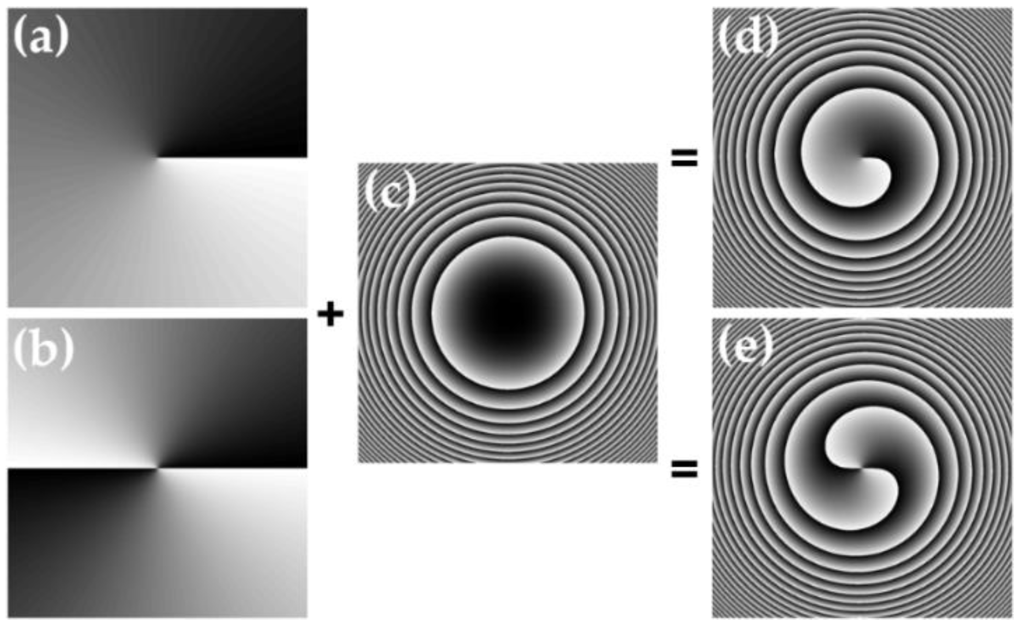
2. Design and Principle

The design of the phase structure is shown in Figure 1. Figure 1a,b represent the spiral phase of the optical vortices with topological charges m = 1 and m = 2, respectively, where black to white corresponds to the phase value of 0 to 2π. Figure 1c is the circular cubic phase with a modulation range of 0–15π. By inserting the spiral phase distribution into the cubic phase distribution, we can get the superimposed phase structure shown in Figure 1d,e, respectively, which can be expressed as
φ = + βr3
where θ = arctan(y/x), r = (x2 + y2)1/2, and β is a parameter related to the circular cubic phase modulation. When introduced by the geometric phase with the orientation of the optical axes of the anisotropic media following α = φ/2, Figure 1d,e can also be regarded as the optical axis distribution of the geometric phase element, where black to white indicates the optical axis varying from 0 to π.
The diffraction property of the designed geometric phase element can be analyzed via the Jones calculus. Herein, the Jones matrix of the element can be expressed as
M = cos Γ 2 [ 1 0 0 1 ] i sin Γ 2 [ cos 2 α sin 2 α sin 2 α cos 2 α ]
where Г = 2πΔnd/λ is the phase retardation, Δn and d are, respectively, the birefringence and the thickness of the anisotropic media, which is chosen to be nematic LC E7 in our work, λ is the incident wavelength, and α = φ/2 = ( + βr3)/2. When the geometric phase element is illuminated by a left circularly polarized (LCP) or right circularly polarized (RCP) Gaussian beam with Jones vector Ein = E0·[1 ± i]T (+/− corresponds to LCP/RCP), the output electric field is changed to
E out = M E in = E 0 cos Γ 2 [ 1 ± i ] E 0 i sin Γ 2 exp ( ± i m θ ) exp ( ± i β r 3 ) [ 1 i ]
The first term of Equation (3) stands for the residual Gaussian beam component with the same polarization state of the incidence, which can be eliminated by controlling the geometric phase element to satisfy the half-wave condition, i.e., Г = (2p + 1)π (p = 0, 1, 2,…). The second term corresponds to the component modulated by the designed phase structure, in which the phase term exp(±imθ)exp(±iβr3) reveals the generation of the circular cubic phase modulated optical vortex, and the Jones vector [1 ∓i]T shows the orthogonal circular polarization state to that of the incidence. In other words, for the LCP incidence, the phase modulation is positive, indicating the generation of a RCP optical vortex with a positive topological charge modulated by the positive circular cubic phase. On the contrary, if the incidence is RCP, the generated optical vortex will be in the LCP state with a negative topological charge modulated by the negative circular cubic phase. On the other hand, the positive or negative circular cubic phase modulation will bring in the autofocusing or autodefocusing property during the propagation process [48,49]. Therefore, it can be deduced that the optical vortices modulated by the circular cubic phase associated with the geometric phase will own the ability of polarization-controllable topological charge and autofocusing/autodefocusing propagation behavior.

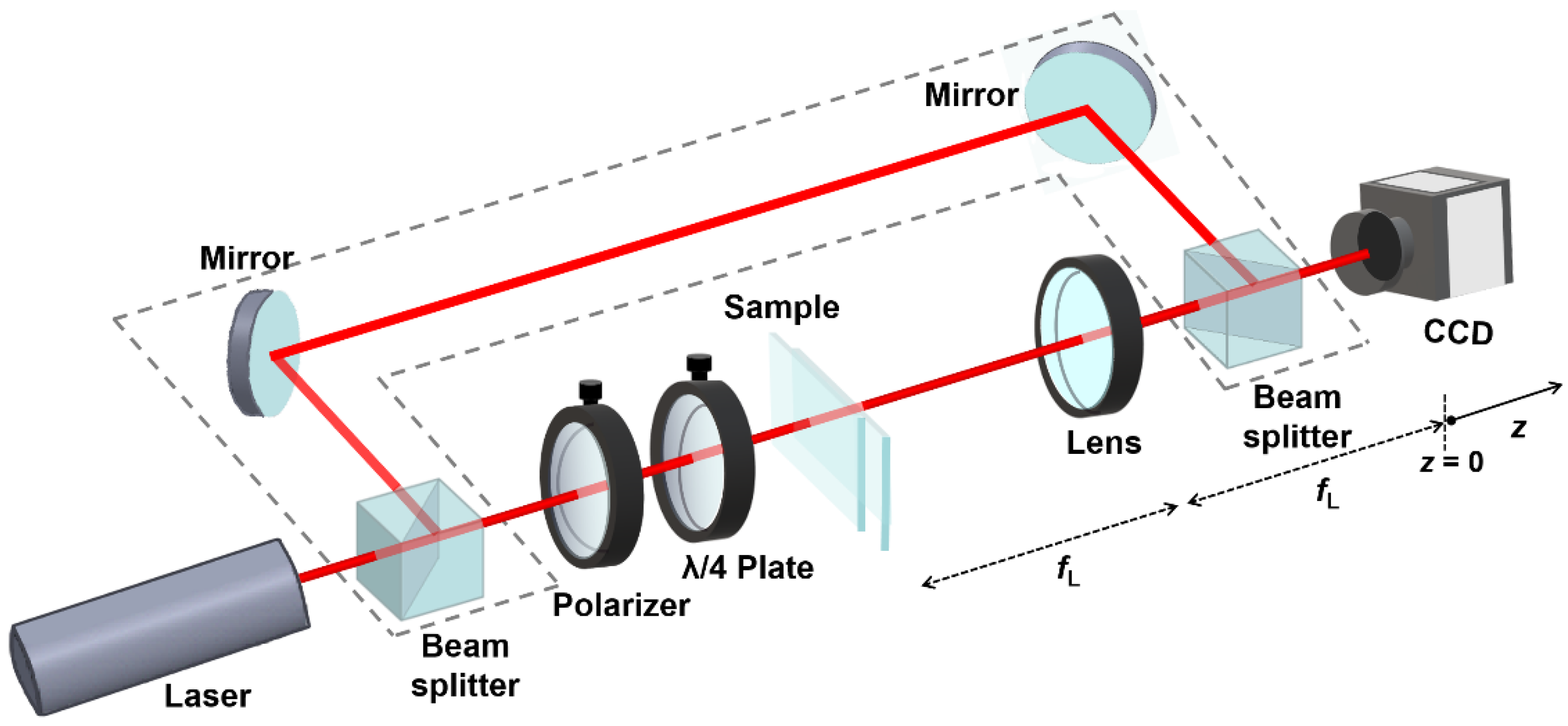
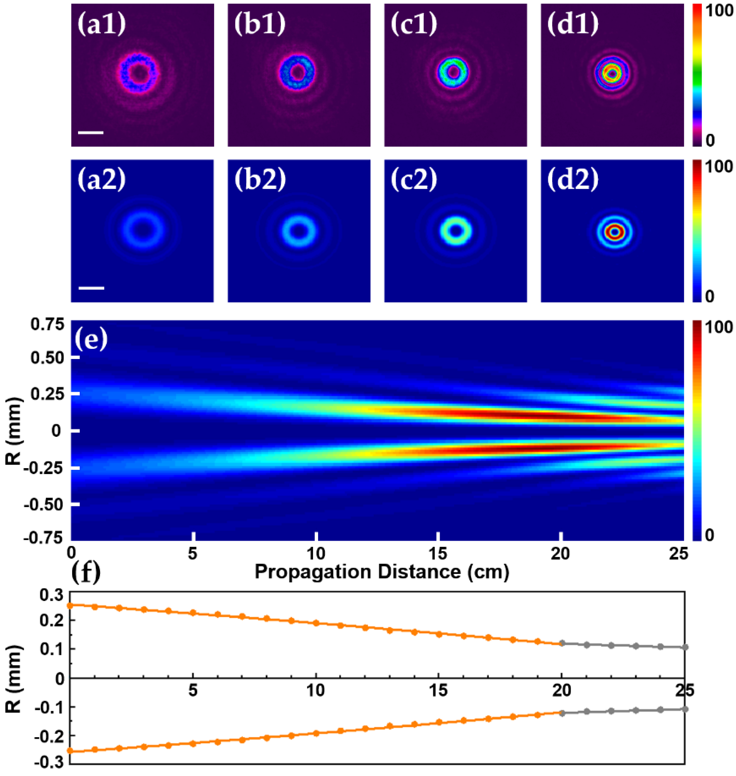
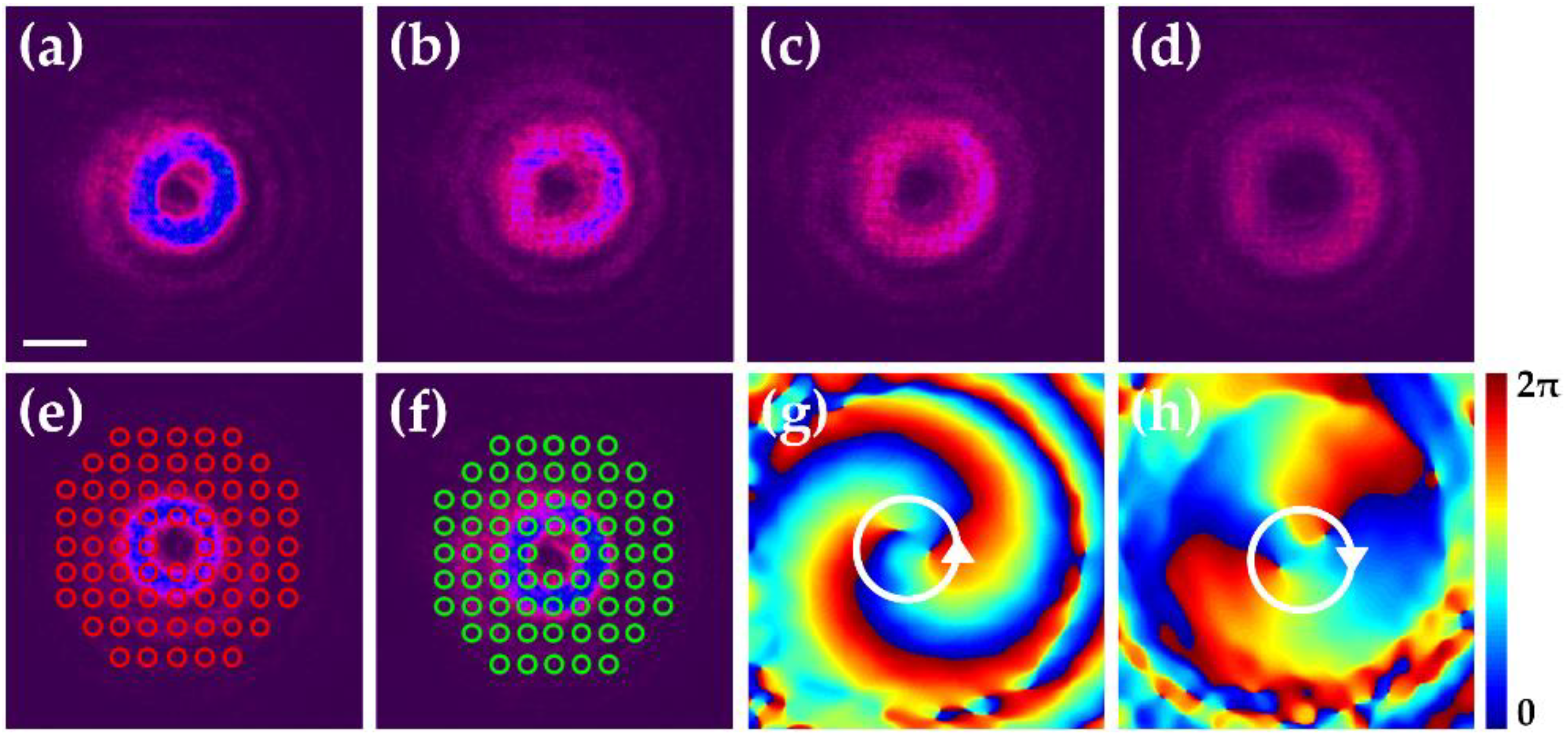
3. Results and Discussions

To carry out the above design, the sulfonic azo-dye SD1 is used as the photoalignment layer to ensure the high-quality alignment of LCs, and the digital micro-mirror device (DMD)-based microlithography system is employed to realize the precise transfer of the above superimposed phase patterns to the LC cell [40], which is composed of two indium-tin-oxide glass substrates spin-coated with SD1 and separated by 6 μm spacers. After an eighteen-step five-time-partly overlapping exposure process [41] and the capillary filling of LC E7 to the cell, the geometric phase element with designed spatially variant optical axes distribution can thus be formed. Figure 2a,b display the micrographs of the fabricated LC samples with m = 1 and m = 2, respectively, which are obtained by observing the samples under an optical microscope with crossed polarizers. The number of the fringes in the micrograph is doubled compared to that of the phase structure shown in Figure 1d,e, which is due to the fact that when the optical axes of the LCs orientate from 0 to π, the bright-to-dark varies twice under the observation between two crossed polarizers. Although there is a tiny misalignment point or defect point induced by the spatially variant distribution of the LC molecules [50] at the center of the sample, the consecutive variation of the brightness reveals the continuous orientation of the LC molecules as designed.
An optical setup shown in Figure 3 is built to test the performance of the LC samples and verify the properties and propagation dynamics of the optical vortices under the modulation of circular cubic phase. For the generation of the modulated optical vortices, a He-Ne laser beam with wavelength λ = 632.8 nm (~1 mm in diameter) passes through a polarizer, a λ/4 plate, the LC sample, and a lens with focal length fL = 10 cm in sequence. The intensity distribution of the modulated optical vortices at different propagation distances can thus be captured by a CCD. Herein, the lens is set at a distance fL away from the sample to perform the Fourier transform, and the focal plane of the lens is defined as the initial observation point where the propagation distance z = 0.
In the following experiments, the LC geometric phase sample with m = 2 is taken for demonstration. A voltage of 2.5 V is applied to the LC sample to satisfy the half-wave condition, and the angle between the fast axis of the λ/4 plate and the transmission direction of the polarizer is adjusted to be 45° to ensure the LCP incidence. Figure 4a1–d1 show the detected intensity distributions of the optical vortex under the positive circular cubic phase modulation at the propagation distance z = 0, 5, 10, and 20 cm, respectively. From the images we can see that as the distance increases, the size of the optical vortex becomes smaller and the intensity becomes stronger, indicating an autofocusing propagation process. To better characterize the propagation dynamics, the radii of the inner optical vortex ring at different propagation distances are measured and plotted in Figure 4f. Since the detected intensity of the inner ring reaches the maximum at z = 20 cm, which is the measured focal point, we depict the propagation trajectories in two stages. Before z = 20 cm, as shown by the fitted curves based on the orange dots, the modulated optical vortex accelerates inwards with a parabolic trajectory. Afterwards, although the radius of the inner ring still decreases but in a linear trajectory with a small slope, the intensity starts to weaken, and the sub-rings observed in experiments which originate from the circular cubic phase modulation gradually become stronger. These experimental results are basically consistent with the cross-section and side-view intensity distribution simulations carried out by MATLAB based on the Beam Propagation Method [51,52] (simulation parameters: diameter of the incident Gaussian beam, 1 mm; β, 110; size of the LC sample, 1.2 mm × 1.2 mm) respectively shown in Figure 4a2–d2 and e, including the beam size, the appearance of the side lobes and the position of the focal plane (also at about z = 20 cm in the simulation), which validates the autofocusing property of the optical vortex under the positive circular cubic phase modulation.
The optical vortex modulated by the negative circular cubic phase is also investigated via tuning the fast axis of the λ/4 plate to be 135° to the polarizer to obtain the RCP incidence. Figure 5a–d show the detected intensity distributions also at the propagation distance z = 0, 5, 10, and 20 cm, respectively. Compared to Figure 4a–d, the size of the optical vortex in this case obviously increases and the intensity decreases with the increase of the propagation distance, exhibiting an autodefocusing propagation behavior. Meanwhile, the switching between the autofocusing optical vortex and autodefocusing optical vortex realized by changing the helicity of the incident circular polarization is also experimentally verified. In addition to the intensity distributions, the polarization and phase distributions of the modulated optical vortices are also characterized. The measurement of the polarization distribution is based on the digital holography system and the Stokes method [53], and the experimental results are shown in Figure 5e,f with the modulated optical vortices at z = 0 displayed in the background. From the images, we can see that the red/green ellipses vividly reveal the RCP/LCP feature of the optical vortex modulated by the positive/negative circular cubic phase. For the phase distribution, the characterization is based on the setup shown in Figure 3 with the optical path marked by the gray dashed lines included. That is, a reference Gaussian beam is obtained from a beam splitter, reflected by two mirrors, and then interferes with the object optical vortex beam after another beam splitter. The interferograms are captured by the CCD and analyzed to unwrap the spatial phase distributions of the object beams [54]. Figure 5e,f show the measured phase distributions of the optical vortex modulated by the positive and negative circular cubic phase, respectively. In Figure 5e, the spiral phase varies counterclockwise from 0–2π twice, revealing the positive topological charge with m = +2, while in Figure 5f, the spiral phase varies from 0–2π also twice but clockwise, revealing the m = −2 topological charge value. All these experimental observations and analyses coincide well with the aforementioned theoretical predictions.
Furthermore, as the Airy beams generated based on the cubic phase modulation in the Cartesian coordinate own self-healing property, we also studied the potential self-healing feature of the optical vortex under the circular cubic phase modulation. Especially for the autofocusing propagation behavior, it can also be regarded as the result of the inward transverse acceleration [48,49] of the 1D Airy beam [26]. A needle with micrograph shown in Figure 6a is used as an obstacle to block part of the optical vortex modulated by the positive circular cubic phase. Figure 6b exhibits the destroyed intensity distribution at the propagation distance z = 5 cm. Along with the increase of the propagation distance, as shown in Figure 6c,d, the broken ring is gradually recovered. When the propagation distance increases to z = 20 cm, as shown in Figure 6e, the ring shape of the optical vortex is basically restored as before, indicating that the circular cubic phase modulated autofocusing optical vortex does have self-healing capability to a certain extent.

4. Conclusions

In conclusion, we propose and demonstrate the circular cubic phase modulated optical vortex via designed LC geometric phase elements. The LC samples are fabricated through the SD1-based photoalignment technology and the DMD-based microlithography system. The optical vortex modulated by the positive circular cubic phase is endowed with the autofocusing property, and the experimental results of the propagation dynamics match well with the simulations. In addition, the switching from the autofocusing state with the positive topological charge to the autodefocusing state with the negative topological charge can be flexibly realized by adjusting the helicity of the incident circular polarization to apply the negative circular cubic phase modulation. Moreover, it is experimentally found that the modulated optical vortex also possesses self-healing capability. The enriched properties of the optical vortices under the circular cubic phase modulation may facilitate their better applications in optical manipulation, high-resolution imaging, and so on.

Author Contributions

Conceptualization, B.W.; experiment and simulation, H.X., Y.Z.; writing, B.W.; editing, J.Z., S.L., P.L.; supervision, B.W., Y.W., J.Z. All authors have read and agreed to the published version of the manuscript.

Funding

This research was funded by the National Natural Science Foundation of China (NSFC) (12074313, 12074312, 12174309), Fundamental Research Funds for the Central Universities (3102019JC008), Research Project of the National University of Defense Technology (ZK20-41), Advanced Laser Technology Laboratory Foundation of Anhui Province (AHL2021QN03), CAST Creative Foundation (1020J20210117), and Technology Domain Fund of 173 Project (2021-JCJQ-JJ-0284).

Conflicts of Interest

The authors declare no conflict of interest.

References

  1. Forbes, A.; Oliveira, M.; Dennis, M.R. Structured light. Nat. Photonics 2021, 15, 253–262. [Google Scholar] [CrossRef]
  2. Yao, A.M.; Padgett, M.J. Orbital angular momentum: Origins, behavior and applications. Adv. Opt. Photonics 2011, 3, 161–204. [Google Scholar] [CrossRef]
  3. Fu, S.; Shang, Z.; Hai, L.; Huang, L.; Lv, Y.; Gao, C. Orbital angular momentum comb generation from azimuthal binary phases. Adv. Photonics Nexus 2022, 1, 016003. [Google Scholar] [CrossRef]
  4. Paterson, L.; MacDonald, M.P.; Arlt, J.; Sibbett, W.; Bryant, P.E.; Dholakia, K. Controlled rotation of optically trapped microscopic particles. Science 2001, 292, 912–914. [Google Scholar] [CrossRef]
  5. Grier, D.G. A revolution in optical manipulation. Nature 2003, 424, 810–816. [Google Scholar] [CrossRef] [PubMed]
  6. Yang, Y.; Ren, Y.X.; Chen, M.; Arita, Y.; Rosales-Guzmán, C. Optical trapping with structured light: A review. Adv. Photonics 2021, 3, 034001. [Google Scholar] [CrossRef]
  7. Molina-Terriza, G.; Torres, J.P.; Torner, L. Twisted photons. Nat. Phys. 2007, 3, 3050–3310. [Google Scholar] [CrossRef]
  8. Wang, X.L.; Cai, X.D.; Su, Z.E.; Chen, M.C.; Wu, D.; Li, L.; Liu, N.L.; Lu, C.Y.; Pan, J.W. Quantum teleportation of multiple degrees of freedom of a single photon. Nature 2015, 518, 516–519. [Google Scholar] [CrossRef]
  9. Hell, S.W.; Wichmann, J. Breaking the diffraction resolution limit by stimulated emission: Stimulated-emission depletion fluorescence microscopy. Opt. Lett. 1994, 19, 780–782. [Google Scholar] [CrossRef]
  10. Yan, L.; Gregg, P.; Karimi, E.; Rubano, A.; Marrucci, L.; Boyd, R.; Ramachandran, S. Q-plate enabled spectrally diverse orbital-angular-momentum conversion for stimulated emission depletion microscopy. Optica 2015, 2, 900–903. [Google Scholar] [CrossRef] [Green Version]
  11. Fang, X.; Ren, H.; Gu, M. Orbital angular momentum holography for high-security encryption. Nat. Photonics 2020, 14, 102–108. [Google Scholar] [CrossRef]
  12. Lee, J.H.; Foo, G.; Johnson, E.G.; Swartzlander, G.A. Experimental verification of an optical vortex coronagraph. Phys. Rev. Lett. 2006, 97, 053901. [Google Scholar] [CrossRef]
  13. Zhou, Y.; Cui, Z.; Han, Y. Polarization and coherence properties in self-healing propagation of a partially coherent radially polarized twisted beam. Opt. Express 2022, 30, 23448–23462. [Google Scholar] [CrossRef]
  14. Žukauskas, A.; Malinauskas, M.; Brasselet, E. Monolithic generators of pseudo-nondiffracting optical vortex beams at the microscale. Appl. Phys. Lett. 2013, 103, 181122. [Google Scholar] [CrossRef]
  15. Gutiérrez-Vega, J.C.; López-Mariscal, C. Nondiffracting vortex beams with continuous orbital angular momentum order dependence. J. Opt. A Pure Appl. Opt. 2008, 10, 015009. [Google Scholar] [CrossRef]
  16. Vetter, C.; Steinkopf, R.; Bergner, K.; Ornigotti, M.; Nolte, S.; Gross, H.; Szameit, A. Realization of free-space long-distance self-healing Bessel beams. Laser Photonics Rev. 2019, 13, 1900103. [Google Scholar] [CrossRef]
  17. Bouchal, Z.; Courtial, J. The connection of singular and nondiffracting optics. J. Opt. A Pure Appl. Opt. 2004, 6, S184–S188. [Google Scholar] [CrossRef]
  18. Kovalev, A.A.; Kotlyar, V.V. Orbital angular momentum of superpositions of optical vortices perturbed by a sector aperture. Photonics 2022, 9, 531. [Google Scholar] [CrossRef]
  19. Tsukamoto, Y.; Yoshida, H.; Ozaki, M. Generation of a focused optical vortex beam using a liquid crystal spiral zone plate. Opt. Express 2022, 30, 8667–8675. [Google Scholar] [CrossRef]
  20. Kovalev, A.A.; Kotlyar, V.V.; Porfirev, A.P. Auto-focusing accelerating hyper-geometric laser beams. J. Opt. 2016, 18, 025610. [Google Scholar] [CrossRef]
  21. Liu, Y.; Xu, C.; Lin, Z.; Wu, Y.; Wu, Y.; Wu, L.; Deng, D. Auto-focusing and self-healing of symmetric odd-Pearcey Gauss beams. Opt. Lett. 2020, 45, 2957–2960. [Google Scholar] [CrossRef]
  22. Dai, H.T.; Liu, Y.J.; Luo, D.; Sun, X.W. Propagation dynamics of an optical vortex imposed on an Airy beam. Opt. Lett. 2010, 35, 4075–4077. [Google Scholar] [CrossRef]
  23. Zhou, J.; Liu, Y.; Ke, Y.; Luo, H.; Wen, S. Generation of Airy vortex and Airy vector beams based on the modulation of dynamic and geometric phases. Opt. Lett. 2015, 40, 3193–3196. [Google Scholar] [CrossRef]
  24. Wei, B.Y.; Chen, P.; Ge, S.J.; Duan, W.; Hu, W.; Lu, Y.Q. Generation of self-healing and transverse accelerating optical vortices. Appl. Phys. Lett. 2016, 109, 121105. [Google Scholar] [CrossRef]
  25. Liu, Y.; Chen, W.; Tang, J.; Xu, X.; Chen, P.; Ma, C.Q.; Zhang, W.; Wei, B.Y.; Ming, Y.; Cui, G.X.; et al. Switchable second-harmonic generation of Airy beam and Airy vortex beam. Adv. Opt. Mater. 2021, 9, 2001776. [Google Scholar] [CrossRef]
  26. Siviloglou, G.A.; Broky, J.; Dogariu, A.; Christodoulides, D.N. Observation of accelerating Airy beams. Phys. Rev. Lett. 2007, 99, 213901. [Google Scholar] [CrossRef]
  27. Kotlyar, V.V.; Kovalev, A.A. Airy beam with a hyperbolic trajectory. Opt. Commun. 2014, 313, 290–293. [Google Scholar] [CrossRef]
  28. Efremidis, N.K.; Chen, Z.; Segev, M.; Christodoulides, D.N. Airy beams and accelerating waves: An overview of recent advances. Optica 2019, 6, 686–701. [Google Scholar] [CrossRef]
  29. Baumgartl, J.; Mazilu, M.; Dholakia, K. Optically mediated particle clearing using Airy wavepackets. Nat. Photonics 2008, 2, 675–678. [Google Scholar] [CrossRef]
  30. Polynkin, P.; Kolesik, M.; Moloney, J.V.; Siviloglou, G.A.; Christodoulides, D.N. Curved plasma channel generation using ultraintense Airy beams. Science 2009, 324, 229–232. [Google Scholar] [CrossRef]
  31. Chong, A.; Renninger, W.H.; Christodoulides, D.N.; Wise, F.W. Airy-Bessel wave packets as versatile linear light bullets. Nat. Photonics 2010, 4, 103–106. [Google Scholar] [CrossRef]
  32. Gu, Y.; Gbur, G. Scintillation of Airy beam arrays in atmospheric turbulence. Opt. Lett. 2010, 35, 3456–3458. [Google Scholar] [CrossRef]
  33. Vettenburg, T.; Dalgarno, H.I.C.; Nylk, J.; Coll-Lladó, C.; Ferrier, D.E.K.; Cižmár, T.; Gunn-Moore, F.J.; Dholakia, K. Light-sheet microscopy using an Airy beam. Nat. Methods 2014, 11, 541–544. [Google Scholar] [CrossRef]
  34. Guo, W.L.; Chen, K.; Wang, G.M.; Luo, X.Y.; Cai, T.; Zhang, C.B.; Feng, Y. Airy beam generation: Approaching ideal efficiency and ultra wideband with reflective and transmissive metasurfaces. Adv. Opt. Mater. 2020, 8, 2000860. [Google Scholar] [CrossRef]
  35. Wei, B.Y.; Liu, S.; Chen, P.; Qi, S.X.; Zhang, Y.; Hu, W.; Lu, Y.Q.; Zhao, J.L. Vortex Airy beams directly generated via liquid crystal q-Airy-plates. Appl. Phys. Lett. 2018, 112, 121101. [Google Scholar] [CrossRef]
  36. Zhan, Q. Cylindrical vector beams: From mathematical concepts to applications. Adv. Opt. Photonics 2009, 1, 1–57. [Google Scholar] [CrossRef]
  37. Wei, B.; Qi, S.; Liu, S.; Li, P.; Zhang, Y.; Han, L.; Zhong, J.; Hu, W.; Lu, Y.; Zhao, J. Auto-transition of vortex- to vector-Airy beams via liquid crystal q-Airy-plates. Opt. Express 2019, 27, 18848–18857. [Google Scholar] [CrossRef]
  38. Li, H.; Liu, H.; Chen, X. Nonlinear generation of Airy vortex beam. Opt. Express 2018, 26, 21204–21209. [Google Scholar] [CrossRef]
  39. Dai, H.T.; Liu, Y.J.; Luo, D.; Sun, X.W. Propagation properties of an optical vortex carried by an Airy beam: Experimental implementation. Opt. Lett. 2011, 36, 1617–1619. [Google Scholar] [CrossRef]
  40. Wei, B.Y.; Hu, W.; Ming, Y.; Xu, F.; Rubin, S.; Wang, J.G.; Chigrinov, V.; Lu, Y.Q. Generating switchable and reconfigurable optical vortices via photopatterning of liquid crystals. Adv. Mater. 2014, 26, 1590–1595. [Google Scholar] [CrossRef]
  41. Chen, P.; Wei, B.Y.; Ji, W.; Ge, S.J.; Hu, W.; Xu, F.; Chigrinov, V.; Lu, Y.Q. Arbitrary and reconfigurable optical vortex generation: A high-efficiency technique using director-varying liquid crystal fork gratings. Photon. Res. 2015, 3, 133–139. [Google Scholar] [CrossRef]
  42. Chen, P.; Wei, B.Y.; Hu, W.; Lu, Y.Q. Liquid-crystal-mediated geometric phase: From transmissive to broadband reflective planar optics. Adv. Mater. 2019, 32, 1903665. [Google Scholar] [CrossRef]
  43. Liu, S.; Qi, S.; Li, P.; Wei, B.; Chen, P.; Hu, W.; Zhang, Y.; Gan, X.; Zhang, P.; Lu, Y.; et al. Analogous optical activity in free space using a single Pancharatnam-Berry phase element. Laser Photonics Rev. 2022, 16, 2100291. [Google Scholar] [CrossRef]
  44. Liu, S.J.; Chen, P.; Ge, S.J.; Zhu, L.; Zhang, Y.H.; Lu, Y.Q. 3D engineering of orbital angular momentum beams via liquid-crystal geometric phase. Laser Photonics Rev. 2022, 16, 2200118. [Google Scholar] [CrossRef]
  45. Zhu, L.; Xu, C.T.; Chen, P.; Zhang, Y.H.; Liu, S.J.; Chen, Q.M.; Ge, S.J.; Hu, W.; Lu, Y.Q. Pancharatnam-Berry phase reversal via opposite-chirality-coexisted superstructures. Light Sci. Appl. 2022, 11, 135. [Google Scholar] [CrossRef]
  46. Yuan, R.; Xu, C.T.; Cao, H.; Zhang, Y.H.; Wang, G.Y.; Chen, P.; Lu, Y.Q.; Hu, W. Spin-decoupled transflective spatial light modulations enabled by a piecewise-twisted anisotropic monolayer. Adv. Sci. 2022, 9, 2202424. [Google Scholar] [CrossRef]
  47. Liu, S.; Qi, S.; Li, Y.; Wei, B.; Li, P.; Zhao, J. Controllable oscillated spin Hall effect of Bessel beam realized by liquid crystal Pancharatnam-Berry phase elements. Light Sci. Appl. 2022, 11, 219. [Google Scholar] [CrossRef]
  48. Zhang, Y.; Wei, B.; Liu, S.; Li, P.; Chen, X.; Wu, Y.; Dou, X.; Zhao, J. Circular Airy beams realized via the photopatterning of liquid crystals. Chin. Opt. Lett. 2020, 18, 080008. [Google Scholar] [CrossRef]
  49. Wei, B.; Zhang, Y.; Li, P.; Liu, S.; Hu, W.; Lu, Y.; Wu, Y.; Dou, X.; Zhao, J. Liquid-crystal splitter for generating and separating autofocusing and autodefocusing circular Airy beams. Opt. Express 2020, 28, 26151–26160. [Google Scholar] [CrossRef]
  50. Slussarenko, S.; Murauski, A.; Du, T.; Chigrinov, V.; Marrucci, L.; Santamato, E. Tunable liquid crystal q-plates with arbitrary topological charge. Opt. Express 2011, 19, 4085–4090. [Google Scholar] [CrossRef] [Green Version]
  51. Pregla, R.; Reden, W.V.; Hoekstra, H.J.W.M.; Baghdasaryan, H.V. Beam propagation methods. In Book Photonic Devices for Telecommunications; Guekos, G., Ed.; Springer: Berlin/Heidelberg, Germany, 1999; pp. 35–65. [Google Scholar]
  52. Li, P.; Liu, S.; Peng, T.; Xie, G.; Gan, X.; Zhao, J. Spiral autofocusing Airy beams carrying power-exponent-phase vortices. Opt. Express 2014, 22, 7598–7606. [Google Scholar] [CrossRef] [PubMed]
  53. Liu, S.; Han, L.; Li, P.; Zhang, Y.; Cheng, H.; Zhao, J. A method for simultaneously measuring polarization and phase of arbitrarily polarized beams based on Pancharatnam-Berry phase. Appl. Phys. Lett. 2017, 110, 171112. [Google Scholar] [CrossRef]
  54. Wang, K.; Kemao, Q.; Di, J.; Zhao, J. Deep learning spatial phase unwrapping: A comparative review. Adv. Photonics Nexus 2022, 1, 014001. [Google Scholar] [CrossRef]
Figure 1. Design of the modulation phase structure. The spiral phase of the optical vortex with topological charge (a) m = 1 and (b) m =2, respectively. (c) The circular cubic phase with a modulation range of 0–15π. (d,e) The superimposed phase structures of the former two types.
Crystals 12 01356 g001
Figure 2. Micrographs of the fabricated LC geometric phase samples with (a) m = 1 and (b) m = 2, respectively. The scale bar is 200 μm.
Crystals 12 01356 g002
Figure 3. Illustration of the optical setup for the generation and detection of optical vortices under the modulation of the circular cubic phase. The optical path and elements within the area marked by the gray dashed lines are designed for the phase measurement of the modulated optical vortices.
Crystals 12 01356 g003
Figure 4. Propagation dynamics of the optical vortex with m =2 under the positive circular cubic phase modulation. (a1d1) Detected and (a2d2) simulated intensity distributions at propagation distance z = 0, 5, 10, and 20 cm, respectively. The scale bar is 200 μm. (e) Simulated side-view intensity distribution of the autofocusing optical vortex. (f) Measured propagation trajectory of the autofocusing optical vortex, in which the orange and gray dots represent the detected radius of the optical vortex, and the orange and gray curves are parabolic and linear fits, respectively.
Crystals 12 01356 g004
Figure 5. (ad) Intensity distributions of the optical vortex under the negative circular cubic phase modulation detected at propagation distance z = 0, 5, 10, and 20 cm, respectively. The scale bar is 200 μm. Measured (e,f) polarization distribution and (g,h) phase distribution of the optical vortex under the positive/negative circular cubic phase modulation. The red and blue ellipses in (e,f) represent RCP and LCP, respectively, and white arrows in (g,h) indicate the twist directions of the spiral phases.
Crystals 12 01356 g005
Figure 6. Demonstration of self-healing property of the modulated optical vortex. (a) Micrograph of the obstacle needle. The scale bar is 500 μm. (be) Intensity distributions of the optical vortex at (a) destroying position z = 5 cm, (b) z = 10 cm, (c) z = 15 cm, and (d) z = 20 cm, respectively.
Crystals 12 01356 g006
Publisher’s Note: MDPI stays neutral with regard to jurisdictional claims in published maps and institutional affiliations.

