Article

Study on the Electromagnetic Characteristics of Ring-Shaped Superconducting Permanent Magnets for Medical Applications

1
Department of Oral Medicine, Stomatological Hospital and Dental School of Tongji University, Shanghai Engineering Research Center of Tooth Restoration and Regeneration, Shanghai 200072, China
2
Department of Electrical Engineering, Shanghai Jiao Tong University, Shanghai 200240, China
3
Department of Prosthodontics, Stomatological Hospital and Dental School of Tongji University, Shanghai Engineering Research Center of Tooth Restoration and Regeneration, Shanghai 200072, China
*
Author to whom correspondence should be addressed.
Crystals 2022, 12(10), 1438; https://doi.org/10.3390/cryst12101438
Submission received: 8 September 2022 / Revised: 6 October 2022 / Accepted: 9 October 2022 / Published: 12 October 2022
(This article belongs to the Special Issue Research on High-Temperature Superconducting Materials)

Abstract

:
The ring-shaped superconducting permanent magnet, with its great advantages in flexible sizing and trapped field, has become a potential candidate for portable medical applications. However, due to the complex geometry involved, it is difficult to predict its electromagnetic performance by traditional numerical methods. This paper presents a field-circuit coupling method to study the entire magnetization process of the ring-shaped magnet. Firstly, the principle of the numerical method is introduced and it is proved to be sufficient for a ring-shaped magnet with a large turn number. Then, the numerical model is used to discuss the relationship between pulse waveform and magnitude of trapped field. Next, the accumulation effect under multi-pulse magnetization is theoretically analyzed and proved by both experiments and simulation. Finally, based on the numerical model, a study on the decay process of ring-shaped magnets is also presented. Conclusions from this paper will be helpful for obtaining the optimization strategy of magnetization of ring-shaped magnets for practical medical applications.

1. Introduction

At present, magnetic resonance imaging (MRI) is practically used in the diagnosis of oral and maxillofacial tumors [1] and temporomandibular joint diseases [2] in the department of stomatology. In addition, it is found that MRI can also obtain clear images of tooth structures such as enamel, dentin, pulp and periodontal tissue; it can distinguish carious lesions and micro-crack structures; it can also be used to assess decay, vitality and angiogenesis; detect early-stage periapical lesions; and differentiate periapical periodontitis from cystic lesions [3]. Therefore, MRI can become a safe and effective auxiliary examination method in the research and clinical treatment of endodontics in the future. However, due to the high cost and the risk of transportation, it is currently difficult for MRI to be used in the stomatology department. In recent years, with the great development of high-temperature superconducting (HTS) technology, the ring-shaped superconducting magnet, with its advantages of feasible size and high trapped field, has become a potential candidate for MRI systems. Portable MRI systems based on this technology can lay the foundation for the improvement of the overall medical level of stomatology.
The ring-shaped trapped field magnet, first proposed by G. A. Levin et al. in 2008 [4], was fabricated through spitting the HTS coated conductors, shaping them into a ring, and stacking them up. Its joint-free structure enables persistent current in the coils without decay and it can achieve a huge range of trapped field by flexibly adjusting the number of turns, with a recent record of 4.60 T trapped field by a double-stacked HTS ring-shaped magnet [5]. Thus, the ring-shaped magnet has been adopted in many industrial applications, including MRI [6,7,8,9,10], superconducting transformers [11], superconducting fault current limiters [12,13,14] and so on.
Magnetization mechanisms and the structural optimization of ring-shaped magnets have been systematically investigated through numerical models and experiments. C. Rong et al. and D. Qiu et al. studied the characteristics of the trapped magnetic field, including relaxation of persistent current and magnetic field stability [15,16], while Vagner Santos da Cruz et al. discussed the voltage behavior of the ring-shaped magnet, classifying different magnetization stages by the magnitude of the induced current [17]. Jie Sheng et al. preliminarily introduced the cumulative effect of the trapped field under multi-pulse magnetization as well as the trapped field under demagnetization [18], and then proposed a hybrid magnet, which combines HTS stack tapes and a ring-shaped magnet to elevate the trapped field [19]. Seyeon Lee et al. proposed a new winding method, named as “Wind-and-Flip”, which cuts the superconducting tape into two parts, winding them as two coils and then flipping one of the coils so as to generate a magnetic field in the same direction [20]. Changxin Chi et al. compared the low-frequency magnetic field shielding effect of coils with different numbers of pancakes [21]. With 80 dB of shielding effectiveness it was shown that ring-shaped magnets could be further applied in precision instruments. Nevertheless, the unique electromagnetic characteristics of the ring-shaped magnet due to its asymmetric structure remain to be discussed.
In this paper, magnetization of a ring-shaped magnet will be analyzed through a field-circuit coupling model. The effect of pulse waveforms on the trapped field will be discussed, and the cumulative effect of the magnetic field under multi-pulse magnetization will be demonstrated by the circuit model. The current distribution of the multi-turn HTS ring-shaped magnet during the decay process has been studied and the working characteristics under different working situations have also been explored to provide a guideline for future magnet design.

2. Modeling Setup

Contrary to superconducting bulks, the induced current in superconducting ring-shaped magnets can only flow in the region where the superconducting layer is located. The traditional three-dimensional finite element modeling is quite complicated and the amount of calculation required is huge. However, because of the restricted induced current path, the magnetization process of the ring-shaped coil can be simulated by the field-circuit coupling method.
As shown in Figure 1, the ring-shaped magnet is placed in between a pair of split copper coils, and the impulse current is generated by the LC oscillating circuit shown in the left figure. The basic parameters of the superconducting tape and the parameters of the LC oscillatory loop are listed in Table 1.
On the basis of the parameters shown in Table 1, the numerical model for ring-shaped magnets is built based on both Finite Element Analysis (FEA) software and MATLAB. The modeling process can be divided into the following steps:
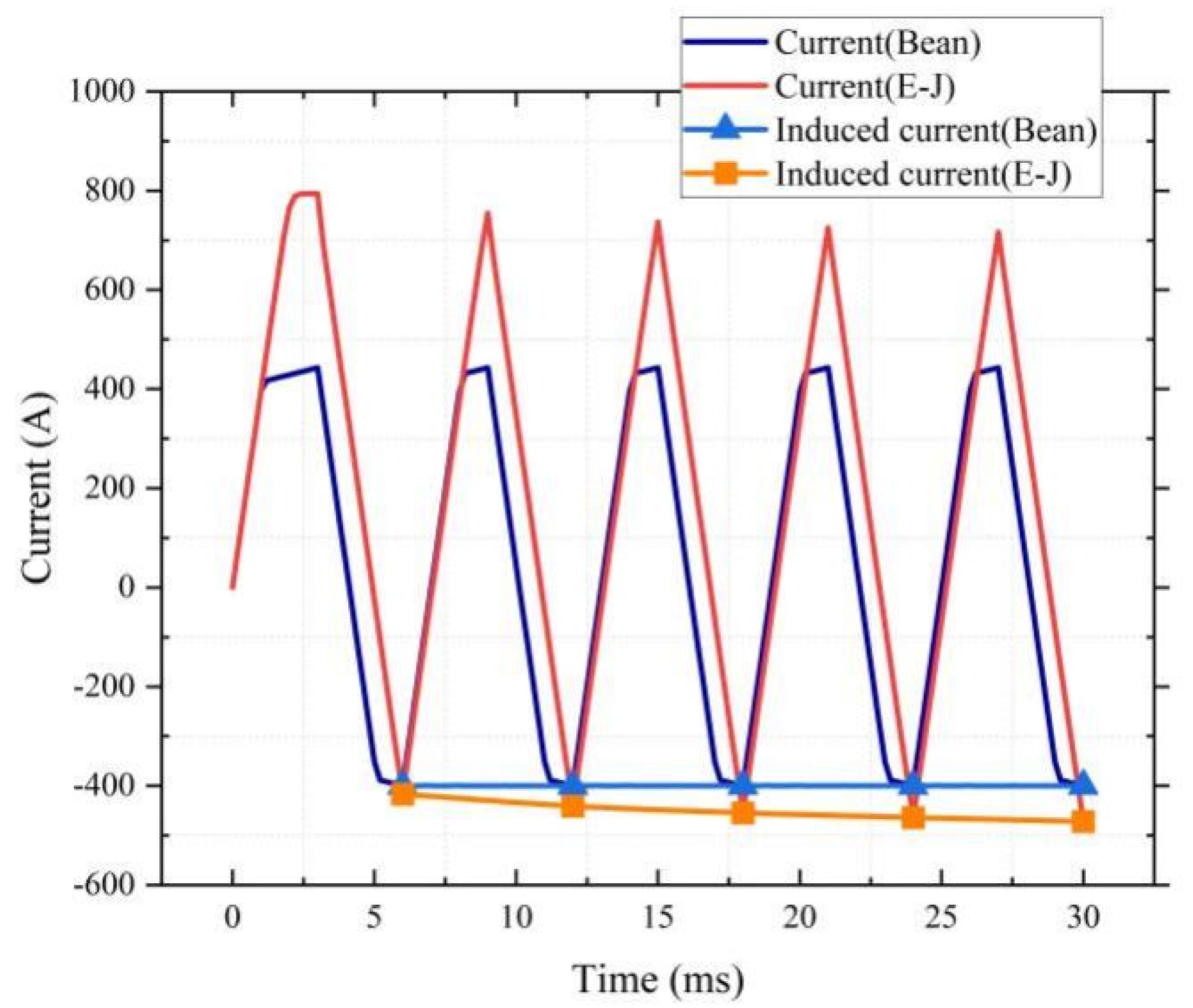
  • Set up an electrical-circuit model in MATLAB. The equation of the circuit model is shown in (1). Since the induced current is strictly limited in the tapes of ring-shaped magnets, the entire magnetization process can be equivalent to a complex circuit problem as shown in (1), and UHTS in (1) is calculated by the E-J exponential equation.
L M 12 M 1 ( N 1 ) M 1 N M 12 L M 2 ( N 1 ) M 1 ( N 1 ) M 1 ( N 1 ) M 2 ( N 1 ) L M 12 M 1 N M 1 ( N 1 ) M 12 L × d i 1 ( t ) d i 2 ( t ) d i N 1 ( t ) d i N ( t ) / d t + U H T S i 1 ( t ) U H T S i 2 ( t ) U H T S i N 1 ( t ) U H T S i N ( t ) = M 1 M 2 M N 1 M N × di applied / dt
U HTS i = U 0 × ( i / I c ) n
In (1), L and Mmn represent the self-inductance and mutual inductance between different superconducting turns, Mk represents the mutual inductance between external split coils and the kth turn of the ring-shaped magnet. ik is the current induced in the kth turn of the ring magnet. iapplied is the impulse current in the external split copper coils. UHTS is the voltage drop over the HTS tape, and U0 is a const value which is set to 0.1 mV. Ic is the critical current value of the HTS tape.
2.
Obtain the inductance matrix in (1). The inductance matrix is calculated by a 3D Finite Element Method (FEM) model in COMSOL which represents the full geometry details of the ring-shaped coil. The FEM model is a static electromagnetic model, and the spatial magnetic energy integration method is used to obtain the self-inductance and mutual inductance of the coil.
Firstly, a static current ik of 1 A is applied to the turn k, the self-inductance L of the turn k can be calculated by (3), and Wm is the total magnetic energy in the entire domain.
W m = 1 2 Li k 2
Then, a static current iapplied of 1 A and −1 A is applied to the external split coil. The mutual inductance Mk can be obtained by (4) and (5).
W m + = 1 2 L i k 2 + 1 2 L ext i applied 2 + M k i k i applied W m = 1 2 L i k 2 + 1 2 L ext i applied 2 M k i k i applied
M k = W m + W m 2 i k i applied
Finally, a similar method is used to calculate the mutual inductance Mjk between turn j and turn k as in (6).
M k = W m + W m 2 i j i k
3.
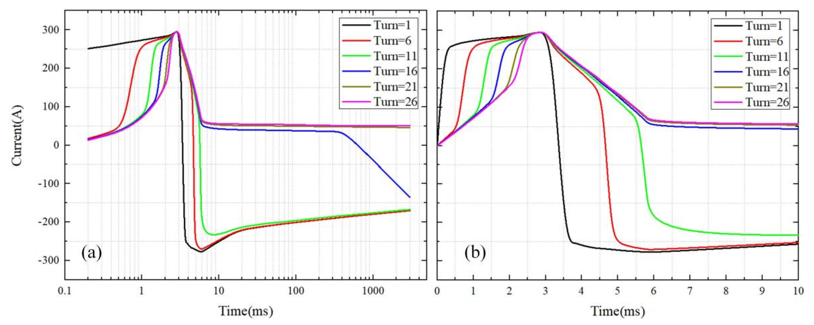
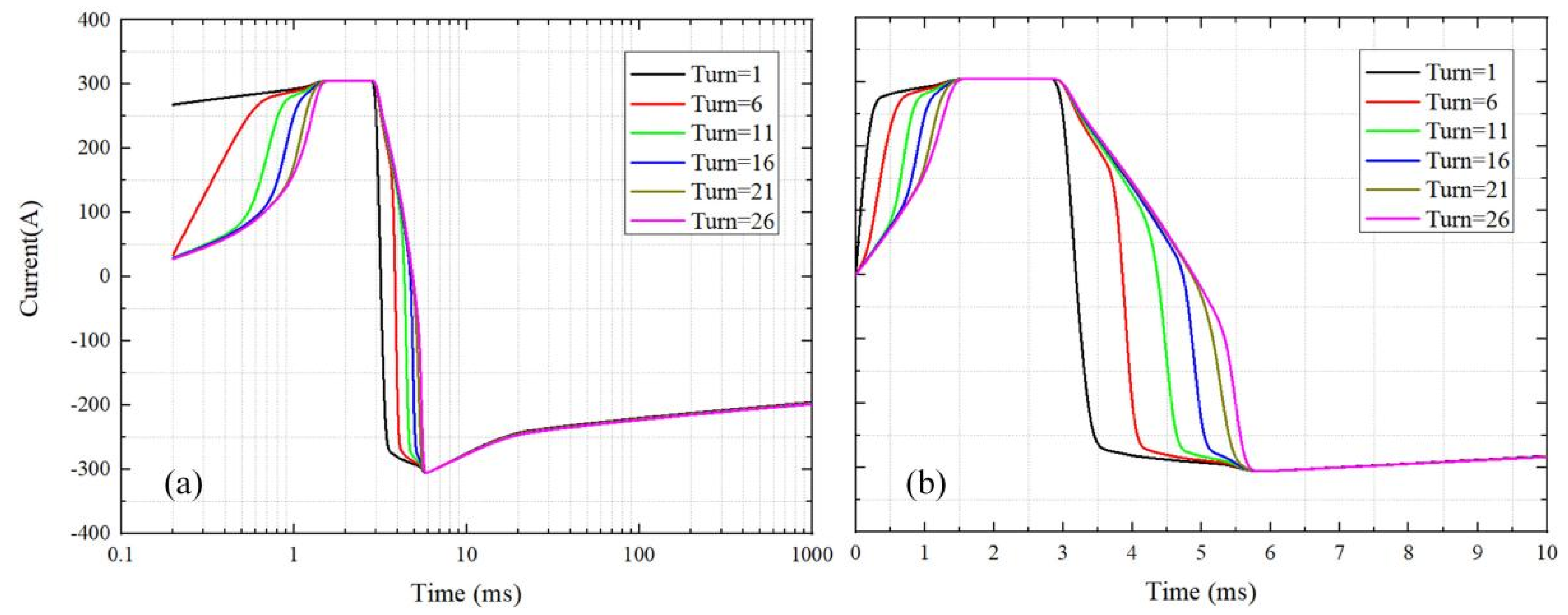
After all the parameters are settled, the high-order partial differential equations are calculated by Newton’s iteration method to obtain the final current distribution in each turn [22].
Figure 2 shows the simulation results of a typical magnetization process for a 51-turn ring-shaped coil. The calculation times of the field-circuit coupling method for a 3-turn ring-shaped magnet and a 51-turn magnet are listed in Table 2; it is quite clear that the field-circuit method can sufficiently improve the efficiency of the simulation, and is appropriate for predicting the magnetization performance of ring-shaped magnets with large turn numbers.

3. Results and Discussions

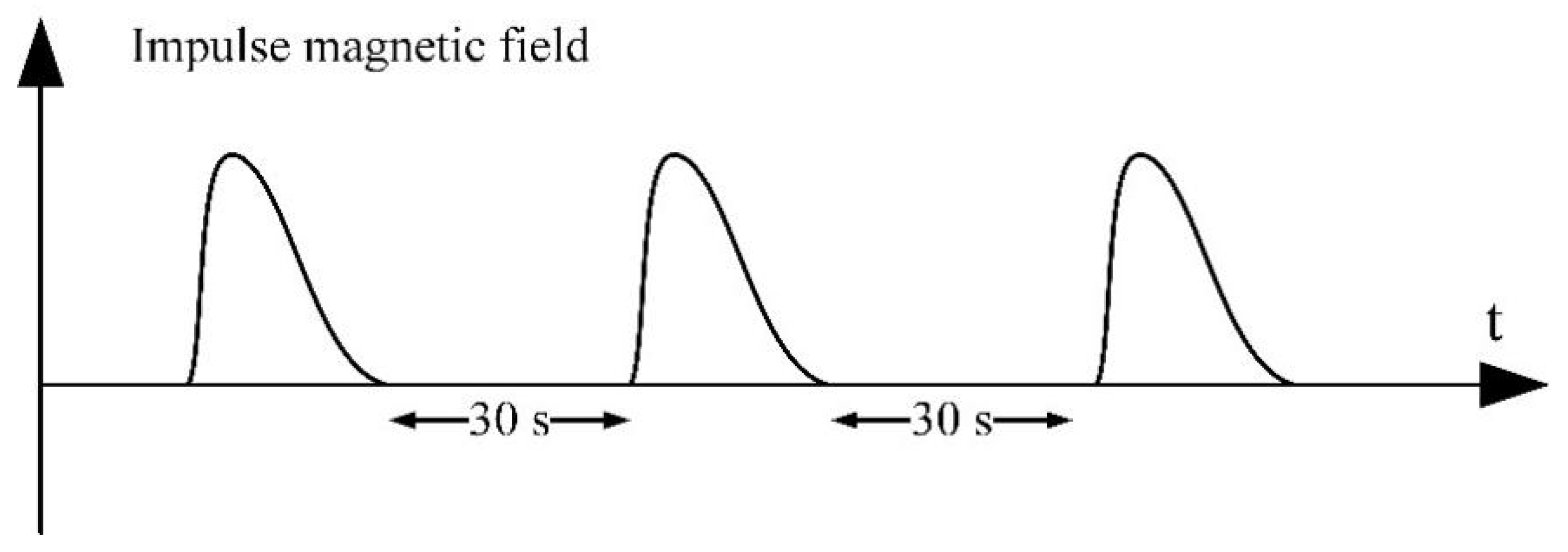
3.1. Effect of Pulse Waveform on Trapped Magnetic Field

In the experiment, a ring-shaped magnet with three turns was used to study the effect of pulse waveform on the trapped magnetic field. A triangle wave in the form of (7) was applied to the numerical circuit model. With a constant maximum amplitude of kT/2, the rising edge time and falling edge time of the pulse waveform was changed by changing the slope of the rising edge (k1) and the slope of the falling edge (k2). The influence of the external magnetic field on the critical current is:
f t = k 1 t 0 < t < k T 2 k 1 k T 2 k 2 t k T 2 k 1 t < k T 2 k 1 + k T 2 k 2
In this section, constant critical current (Ic) and function Ic(B) considering the influence of external magnetic field are used in the numerical model. The detail calculation process of Ic(B) is the same as ref [22].
As shown in Figure 3, in the model based on E-J power law (constant Ic), with k2 constant, decreasing the rising edge rate (k1) would extend the waveform, and the peak value of the total current also shows a descending trend. Because when the induced current did not exceed the critical current, the time for the current reaching the peak value is in inverse proportion to the rising edge rate. With the extension of rising edge, the resistive EHTS component caused the drop in the peak value, which was also the initial current of the falling process, and finally, the reverse current after magnetization correspondingly increased. On the other hand, with k1 constant, in the case of changing the falling edge rate (k2), the total current showed different downtrends, ending as a growing reverse current with the decrease of the falling edge rate, which could be attributed to the longer time for the descending of current.
However, the magnetization characteristics of ring-shaped magnets with function Ic(B) under different impulse waveforms are shown in Figure 4. Different from the model using constant Ic, critical current Ic(B) would decrease with the amplitude of the external magnetic field, causing the peak of the induced current to be smaller than that of the model using constant Ic. Therefore, energy would be stored in the form of EHTS component and finally released at the end of the pulse waveform, leading to a higher reverse current. In addition, as listed in Table 3, if using constant Ic, extending the rising and falling edge times had the same effects on the increase of the reverse current, while it is more efficient to extend the rising edge time if using Ic(B).

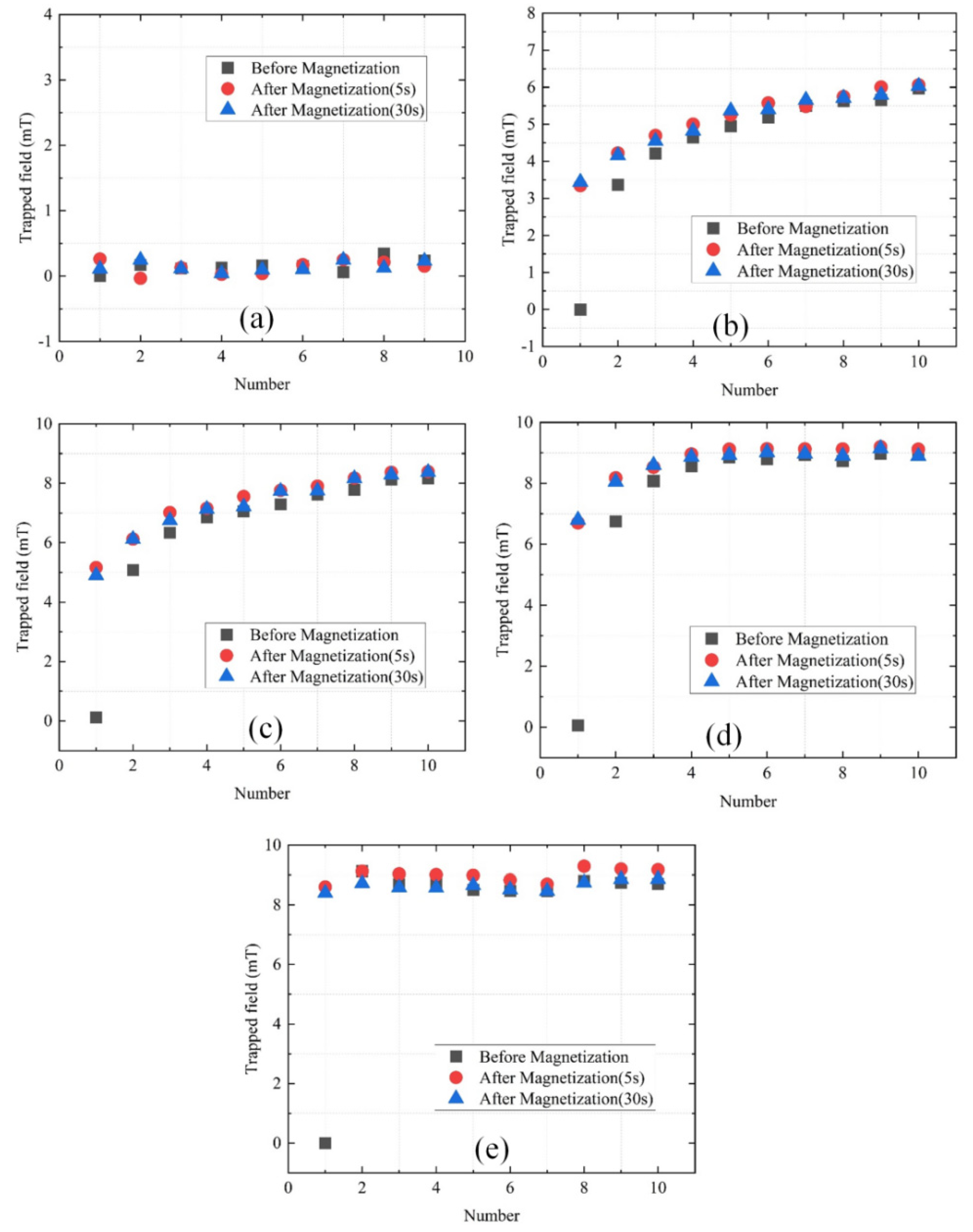
3.2. Effect of Multi-Pulse Magnetization on the Trapped Magnetic Field

3.2.1. Multi-Pulse Magnetization Test

In this section, five voltages, including the shield region (30 V), the saturation region (90 V), and the linear region (60 V, 70 V, 80 V), were applied to the ring-shaped magnet sample. Figure 5 illustrated the process of the multi-pulse magnetization experiment, in which the sample would be magnetized 10 times and the interval before and after the pulse was 30 s.
Figure 6 compared the trapped magnetic field under different voltages, which were recorded by the Hall sensor. When the applied voltage was in the shield or the saturation region, the trapped magnetic field remained constant after multi-pulse magnetization. However, in the linear region, the sample could capture a higher magnetic field value under a pulse waveform with a smaller amplitude after multi-pulse magnetization, from 3.36 mT to 5.97 mT at 60 V (77.67%), 5.07 mT to 8.17 mT at 70 V (61.4%) and 6.74 mT to 8.94 mT at 80 V (32.64%) respectively. This confirmed that multi-pulse magnetization could elevate the trapped magnetic field of the ring-shaped magnet through cumulative effect.

3.2.2. Numerical Analysis of Cumulative Effect

In numerical analysis, EHTS component is regarded as a step function to simplify the calculation, as shown in (8).
E HTS = 0 , i I c A , i > I c A ,   i < I c
In the subsequent calculation, t4k−3 represents the time when the current in the tape reaches the critical current during the rise of the kth pulse magnetization; t4k−2 represents the time when the pulse waveform reaches the peak value; t4k−1 represents the time when the current in the tape reaches the critical current during the drop of the kth pulse magnetization; t4k represents the time of the end of the kth pulse magnetization.
During the first pulse magnetization, the initial value of the current is 0. According to (9) and (10), when the induced current reaches the critical current at t1, the applied current is IcL/M. From t1 onwards, EHTS component should be considered, as shown in (11). Shift terms on both sides of the equation and integrate, as shown in (12). Taking the value obtained at t1 as the initial value as shown in (13), the current in the superconducting tape at t2 is calculated and shown in (14). At this time, the input current of the excitation coil is the maximum value IM. The current at t3 could also be calculated by (11), as shown in (15). Between t3 and t4, the current is below the critical current, thus the current at t4 should be calculated as (16).
L di dt = M di applied dt
i t = M L i applied t
L di dt + A = M di applied dt
Ldi = Mdi applied Adt
i t 1 = I c   i applied t 1 = I c L / M  
i t 2 = M L i applied t 2 A L t 2 t 1
i t 3 = I c   i applied t 3 = L M ( I c + A L t 3 t 1 )
i t 4 = A L t 3 t 1
Taking i(t4) as the input of the second pulse magnetization, the current from t5 to t8 could be calculated through (17). Comparing i(t4) and i(t8), it can be found that the reverse current would increase with the accumulation of pulse magnetization. Meanwhile, the amplitude of the coil would increase and approach the peak value when the current in the tapes reaches the critical current, after which it no longer accumulates.
i t 5 = I c   i applied t 5 = L M ( I c + A L t 3 t 1 )
i t 6 = M L i applied t 6 A L t 6 t 5 + t 3 t 1   i applied t 6 = I M
i t 7 = I c   i applied t 7 = L M ( I c + A L t 7 t 5 + t 3 t 1 )
i t 8 = A L t 7 t 5 + t 3 t 1
For both single-turn and 3-turn ring-shaped magnets, Figure 7 and Figure 8 showed that the reverse current remained constant in the Bean model [23] because the current in the tapes has been limited to the critical current. Conversely, in the model based on E-J power law, the peak value of the induced current would decrease and the reverse current would increase with the accumulation of pulse magnetization, which is in agreement with the experimental results of the multi-pulse magnetization. As a result, it can be found that multiple-pulse magnetization can cause an effective trapped field accumulation in the ring-shaped magnet, so in the linear region of magnetization, practically, a relatively small impulse current can be used to obtain the ideal magnetic field value of a trapped field.

3.3. Decay of the Ring-Shaped Magnet

In this section, a circuit model is adopted to simulate the decay process of the ring-shaped magnet in order to simplify the calculation. There are two situations in the decay process: unsaturated and saturated tapes.

3.3.1. Decay of Unsaturated Tapes in Ring-shaped Magnets

As shown in Figure 9, after the magnetization, current in the tapes on the outside has exceeded the critical current of 200 A, which indicates that the resistive EHTS component is relatively dominant. Therefore, since the external magnetic field no longer changes, the reverse current in these tapes would decay with time, as shown in turn 1 to turn 11. On the other hand, due to the shielding effect, the inner layer of superconducting tapes could be regarded as inductance, on which the current should be zero, as shown in turn 17 to turn 26. Nevertheless, the coil composed of the inner tapes would still induce an additional current to hinder the decrease of the magnetic flux, which leads to the increase of reverse current in turn 12 to turn 16.

3.3.2. Decay of Saturated Tapes in the Ring-Shaped Magnet

In this case, after a pulse magnetization with a relatively large amplitude, the induced reverse current in each turn of the ring-shaped magnet is saturated. Therefore, each turn represents similar characteristics of decay, as shown in Figure 10. The reverse current decays steadily with the time. Once the current falls below the critical current, the coil is no longer resistive and the current remains stable.

4. Conclusions

This paper introduces a field-circuit coupling model to study the magnetization process of ring-shaped magnets. The numerical model proved to be sufficient for predicting the magnetization performance of ring-shaped magnets with large turn numbers. On the basis of the numerical model and experimental platform, the effects of pulse waveform and multi-pulse magnetization on the trapped field of ring-shaped magnets are discussed. By prolonging the rising edge time and the falling edge time, the magnitude of the magnetic field trapped by the ring-shaped magnet can be increased under the condition that the amplitude remains unchanged. In the experiment of multi-pulse magnetization, it can be found that the trapped field gradually accumulates with the increase of magnetization times; in the experiment, when the voltage of external power supply is 80 V, after only five times of pulse magnetization, the trapped field of the ring-shaped magnet eye increases from 6.74 mT to 8.94 mT, reaching the saturation state. This means that the ring-shaped magnet can reach the saturation state under a smaller amplitude of magnetic field using multi-pulse magnetization technology. In order to further expand the application of ring-shaped magnets, we also conducted simulation on the decay process of ring-shaped magnets, which will be very useful for future application in static medical magnets.

Author Contributions

Motivation: C.Z.; writing: W.C.; formal analysis: J.S. (Jinhong Shi); methodology: J.S. (Jie Sheng); funding acquisition, C.Z. All authors have read and agreed to the published version of the manuscript.

Funding

This research was funded by the Youth Project of Shanghai Municipal Health Commission, grant number 20214Y0351.

Institutional Review Board Statement

Not applicable.

Informed Consent Statement

Not applicable.

Data Availability Statement

Not applicable.

Conflicts of Interest

The authors declare no conflict of interest.

References

  1. Lam, P.; Auyeung, K.; Cheng, P.; Wei, W.I.; Yuen, A.P.-W.; Trendell-Smith, N.; Li, J.H.C.; Li, R. Correlating MRI and Histologic Tumor Thickness in the Assessment of Oral Tongue Cancer. Am. J. Roentgenol. 2004, 182, 803–808. [Google Scholar] [CrossRef] [PubMed]
  2. Varol, A.; Sencimen, M.; Gulses, A.; Altug, H.A.; Dumlu, A.; Kurt, B. Diagnostic importance of MRI and CT scans for synovial osteochondromatosis of the temporomandibular joint. Cranio-J. Craniomandib. Pract. 2011, 29, 313–317. [Google Scholar] [CrossRef] [PubMed]
  3. Olt, S.; Jakob, P.M. Contrast-enhanced dental MRI for visualization of the teeth and jaw. Magn. Reson. Med. Off. J. Soc. Magn. Reson. Med. 2004, 52, 174. [Google Scholar] [CrossRef]
  4. Levin, G.A.; Barnes, P.N.; Murphy, J.; Brunke, L.; Long, J.D.; Horwath, J.; Turgut, Z. Persistent current in coils made out of second-generation high temperature superconductor wire. Appl. Phys. Lett. 2008, 93, 631. [Google Scholar] [CrossRef]
  5. Ali, M.Z.; Zheng, J.; Huber, F.; Zhang, Z.; Yuan, W.; Zhang, M. 4.6 T generated by a high-temperature superconducting ring magnet. Supercond. Sci. Technol. 2020, 33, 04LT01. [Google Scholar] [CrossRef]
  6. Kim, W.-S.; Lee, S.; Kim, Y.; Lee, J.Y.; Park, S.-H.; Lee, J.-K.; Hong, G.-W.; Han, J.; Choi, K. Persistent Current Mode of a 1-T-Class HTS Pancake Coil for NMR/MRI Applications. IEEE Trans. Appl. Supercond. 2015, 25, 1–4. [Google Scholar]
  7. Qu, T.; Michael, P.C.; Bascuñán, J.; Lécrevisse, T.; Guan, M.; Hahn, S.; Iwasa, Y. Test of an 8.66-T REBCO Insert Coil with Overbending Radial Build for a 1.3-GHz LTS/HTS NMR Magnet. IEEE Trans. Appl. Supercond. 2017, 27, 1–5. [Google Scholar] [CrossRef]
  8. Qu, T.; Michael, P.C.; Voccio, J.; Bascunan, J.; Hahn, S.; Iwasa, Y. Persistent-current switch for pancake coils of rare earth-barium-copper-oxide high-temperature superconductor: Design and test results of a double-pancake coil operated in liquid nitrogen (77–65 K) and in solid nitrogen (60–57 K). Appl. Phys. Lett. 2016, 109, 4301205. [Google Scholar] [CrossRef] [PubMed] [Green Version]
  9. Kosa, J.; Vajda, I.; Gyore, A. Application possibilities with continuous YBCO loops made of HTS wire. J. Phys. Conf. 2010, 234, 032030. [Google Scholar] [CrossRef]
  10. Lee, H.-G.; Kim, J.-G.; Lee, S.-W.; Kim, W.-S.; Lee, S.-W.; Choi, K.-D.; Hong, G.-W.; Ko, T.-K. Design and fabrication of permanent mode magnet by using coated conductor. Physic C Supercond. 2006, 445, 1099–1102. [Google Scholar] [CrossRef]
  11. Kosa, J.; Vajda, I. Novel 3-Phase Self-Limiting Transformer with Magnetic Flux Applied by Perfect Closed YBCO Wire Loops. IEEE Trans. Appl. Supercond. 2011, 21, 1388–1392. [Google Scholar] [CrossRef]
  12. Kosa, J.; Vajda, I.; Gyore, A.; Kohari, Z. Fault current limiter with novel arrangement of perfect YBCO loops made of HTS wire. In Proceedings of the 14th International Power Electronics and Motion Control Conference EPE-PEMC 2010, Ohrid, Macedonia, 6–8 September 2010. [Google Scholar]
  13. Chen, X.; Zhang, M.; Chen, Y.; Jiang, S.; Gou, H.; Lei, Y.; Shen, B. Superconducting fault current limiter (SFCL) for fail-safe DC-DC conversion: From power electronic device to micro grid protection. Superconductivity 2022, 1, 100003. [Google Scholar] [CrossRef]
  14. Sotelo, G.G.; dos Santos, G.; Sass, F.; Franca, B.W.; Dias, D.H.; Fortes, M.Z.; Polasek, A.; de Andrade, R. A Review of Superconducting Fault Current Limiters Compared with Other Proven Technologies. Superconductivity 2022, 3, 100018. [Google Scholar] [CrossRef]
  15. Rong, C.C.; Barnes, P.N.; Levin, G.A.; Miller, J.D.; Santosusso, D.J.; Fitzpatrick, B.K. Investigation of the Relaxation of Persistent Current in Superconducting Closed Loops Made Out of YBCO Coated Conductors. IEEE Trans. Appl. Supercond. 2015, 25, 1–5. [Google Scholar] [CrossRef]
  16. Qiu, D.; Wu, W.; Pan, Y.; Xu, S.; Zhang, Z.M.; Li, Z.L.; Li, Z.Y.; Wang, Y.; Wang, L.; Zhao, Y.; et al. Experiment and Numerical Analysis on Magnetic Field Stability of Persistent Current Mode Coil Made of HTS-Coated Conductors. IEEE Trans. Appl. Supercond. 2017, 27, 1–5. [Google Scholar] [CrossRef]
  17. da Cruz, V.S.; Telles, G.; Santos, B.M.O.; Ferreira, A.; de Andrade, R. Study of the Voltage Behavior of Jointless Superconducting 2G Loops During Pulse Magnetization. IEEE Trans. Appl. Supercond. 2020, 30, 8200306. [Google Scholar] [CrossRef]
  18. Sheng, J.; Zhang, M.; Wang, Y.; Li, X.; Patel, J.; Yuan, W. A new ring-shape high-temperature superconducting trapped-field magnet. Supercond. Sci. Technol. 2017, 30, 094002. [Google Scholar] [CrossRef] [Green Version]
  19. Sheng, J.; Pan, Y.; Jiang, J.; Li, W.; Shen, B.; Zhang, Z.-W.; Wu, W. A New Concept of a Hybrid Trapped Field Magnet. IEEE Trans. Appl. Supercond. 2019, 29, 0603805. [Google Scholar] [CrossRef]
  20. Lee, S.; Kim, W.-S.; Kim, Y.; Park, S.H.; Lee, J.-K.; Hahn, J.-H.; Hong, G.-W.; Park, I.H.; Park, C.; Choi, K. Characteristics of an HTS Pancake Coil in Persistent Current Mode Using Wind-and-Flip Winding Method. IEEE Trans. Appl. Supercond. 2017, 23, 4601305. [Google Scholar]
  21. Chi, C.; Cai, C.; Zhou, D.; Guo, Y.; Yan, W.; Bai, C.; Liu, Z.; Lu, Y.; Fan, F.; Li, M.; et al. Low-frequency magnetic field shielding effect of artificial joint-free REBCO coils. Supercond. Sci. Technol. 2020, 33, 095001. [Google Scholar] [CrossRef]
  22. Shi, J.; Wang, B.; Shen, B.; Sheng, J. Numerical Study on Ring-shape Superconducting Trapped Field Magnet Based on Circuit Model. IEEE Trans. Appl. Supercond. 2021, 31, 1–5. [Google Scholar] [CrossRef]
  23. Bean, C.P. Magnetization of hard superconductors. Phys. Rev. Lett. Am. Phys. Soc. 1962, 8, 250–253. [Google Scholar] [CrossRef]
Figure 1. Geometry and magnetization system circuit for ring-shaped magnet.
Crystals 12 01438 g001
Figure 2. Current distribution in the first 25 turns of a multi-turn HTS ring-shaped magnet with N = 51 turns.
Crystals 12 01438 g002
Figure 3. The effect of changing the rising edge and falling edge rate on the induced current (constant Ic).
Crystals 12 01438 g003
Figure 4. The effect of changing the rising edge and falling edge rate on the induced current (with Ic(B)).
Crystals 12 01438 g004
Figure 5. Schematic diagram of the multi-pulse magnetization experiment.
Crystals 12 01438 g005
Figure 6. Comparison of the trapped field under multi-pulse magnetization (a) 30 V (b) 60 V (c) 70 V (d) 80 V (e) 90 V.
Crystals 12 01438 g006
Figure 7. Current changes of the single-turn HTS ring-shaped magnet during multi-pulse magnetization.
Crystals 12 01438 g007
Figure 8. Current changes of the multi-turn HTS ring-shaped magnet during multi-pulse magnetization.
Crystals 12 01438 g008
Figure 9. Current distribution of multi-turn HTS ring-shaped magnet during decay (unsaturated): (a) entire magnetization process; (b) the first 10 ms.
Crystals 12 01438 g009
Figure 10. Current distribution of multi-turn HTS ring-shaped magnet during decay(saturated): (a) entire magnetization process; (b) the first 10 ms.
Crystals 12 01438 g010
Table 1. Parameters of external magnetization coils and superconducting materials.
ParametersValues
Inductance of split coil836.8 μH
Resistance of split coil0.13 Ω
Capacitance of C11100 μF/100 V
ManufactureShanghai Superconductor
Geometry10 mm × 75 μm
Critical current (77 K)440 A@77 K
Table 2. Comparison of simulation calculation time.
Turn NumberTime-Consuming
(FEM Method)
Time-Consuming
(Field-Circuit Coupling)
38 h 13 mins1 h (parameter calculation) +
2 min (iteration)
51/2 h (parameter calculation) +
5 min (iteration)
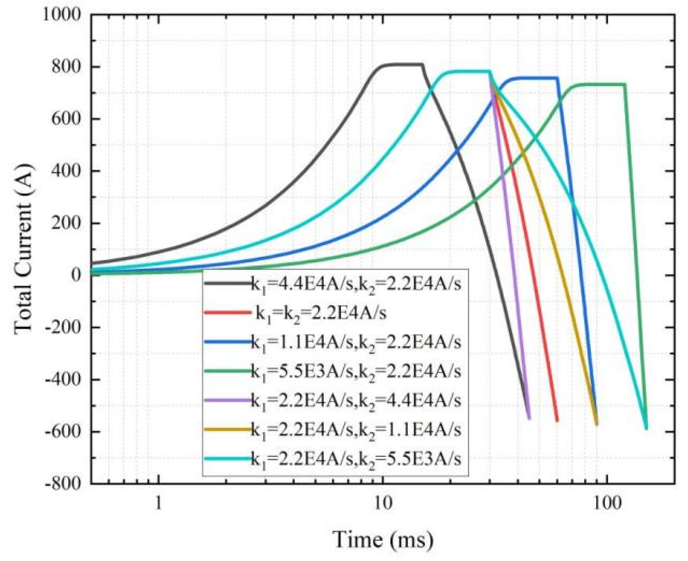
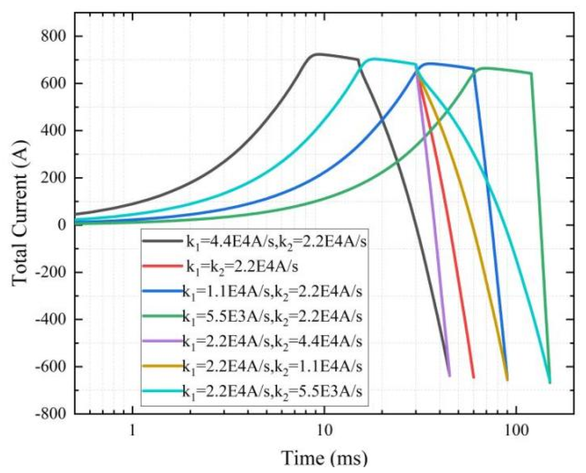
Table 3. The effect of changing the waveform on the induced current.
Reverse Current (Constant Ic)Reverse Current (Ic(B))
k1 = 4.4 × 10⁴, k2 = 2.2 × 10⁴−547.26−637.15
k1 = k2 = 2.2 × 10⁴−557.38−644.93
k1 = 1.1 × 10⁴, k2 = 2.2 × 10⁴−571.13−655.27
k1 = 5.5 × 10³, k2 = 2.2 × 10⁴−587.86−677.78
k1 = 2.2 × 10⁴, k2 = 4.4 × 10⁴−549.09−638.55
k1 = 2.2 × 10⁴, k2 = 1.1 × 10⁴−569.39−653.13
k1 = 2.2 × 10⁴, k2 = 5.5 × 10³−584.57−659.16
Publisher’s Note: MDPI stays neutral with regard to jurisdictional claims in published maps and institutional affiliations.

