Article

Assessment of the Possibility of Galvanic Corrosion in Aluminum Microchannel Heat Exchangers

by
Marzena M. Lachowicz
1,*,
Maciej B. Lachowicz
2 and
Adam Gertruda
3
1
Faculty of Mechanical Engineering, Department of Metal Forming, Welding Technology and Metrology, Wroclaw University of Science and Technology, Ul. Łukasiewicza 7–9, 50-371 Wrocław, Poland
2
Machinefish Materials & Technologies Sp. z o.o. Sp.k., Ul. Duńska 13, 54-427 Wrocław, Poland
3
NRF Sp. z o.o., Ul. Magazynowa 40, 80-180 Janowo Gdańskie, Poland
*
Author to whom correspondence should be addressed.
Crystals 2022, 12(10), 1439; https://doi.org/10.3390/cryst12101439
Submission received: 8 September 2022 / Revised: 3 October 2022 / Accepted: 9 October 2022 / Published: 12 October 2022
(This article belongs to the Section Crystalline Metals and Alloys)

Abstract

:
As part of the work, three used microchannel heat exchangers from different manufacturers were analyzed. For comparison purposes, the new heat exchanger was also subjected to the NSS salt spray test. The material of the Al-Si system used for brazing, as well as the material of the core, were subjected to electrochemical tests. In laboratory tests, polarization curves were determined for the Al-Si material used for brazing, as well as for the core material. On the basis of exchanger research, it was found that a critical problem in the use of microchannel exchangers is galvanic corrosion occurring in the areas of brazed joints. Electrochemical tests have shown that the Al-Si alloy used for brazing has a lower value of corrosion potential than the core material. The existing potential difference is sufficient for galvanic corrosion. Electrochemical corrosion is initiated in the eutectic structure. The soplid solution is the anode and is particularly susceptible to corrosion, which led to its preferential dissolution in the entire volume of the eutectic mixture.

1. Introduction

The use of aluminum alloys for heat exchangers in air-conditioning and refrigeration systems is constantly growing. This is due to the high thermal conductivity of these materials, as well as the ease of their plastic shaping. At the same time, their low density allows the weight and volume of the heat exchangers to be reduced. The design of the exchanger plays a key role in its performance. In the case of classic fin exchangers, the efficiency can be increased by increasing the surface of the fins, which also translates into an increase in its volume and total weight. These design constraints have made the so-called microchannel heat exchangers very popular. Their design is based on aluminum profiles containing microchannels in which the refrigerant flows. The shape of the microchannels provides a larger heat transfer surface than a cylindrical tube, which allows for more intense heat transfer. Between these profiles there are fins, whose arrangement forms a network of small air flow channels (Figure 1). They are brazed to profiles in protective atmospheres (Controlled Atmosphere Brazing, CAB technology) [1,2]. Another method of increasing the efficiency of the systems is coating with a solid desiccant (Desiccant Coated Heat Exchanger, DCHE) as an alternative to vapor compression [3,4,5].
In microchannel exchangers, the fins are usually made of the 3000 series alloy. In this range, the main alloys of AW 3003, AW 3103, and AW 3203 grades are used [6,7,8,9]. Their chemical composition in accordance with PN-EN 573-3 is shown in Table 1. However, the alloys from the 4000 series are used for brazing. These are mainly grades AW 4343, AW 4145, AW 4047, and AW 4045 [10,11]. The chemical composition of common brazing grades is shown in Table 2. Between the microstructure of the brazed joint consisting of the eutectic mixture α(Al)-Si and the core material, a band of dense precipitates zone (BPD) is observed [12,13,14]. Tierce et al. [14] showed that it is caused by the diffusion of silicon from the braze to the parent material. The band of dense precipitates has a higher corrosion potential, and high-density particles in the diffusion zone have been identified as α-AlFeMnSi [15,16]. During brazing, apart from silicon, copper also diffuses, but in this case, the diffusion occurs towards the core [15,17]. Annealing favors the increase in the diffusion of silicon [15]. The influence of the brazing conditions translates into the geometry of the brazed joint, which affects its mechanical properties, but does not affect the nature or composition of the phases forming the microstructure [11].
The requirements for a heat exchanger are tightened by its operating conditions, such as pressure, dynamically changing temperature, and corrosive media. An important issue is to achieve high operational reliability. There is a belief that the use of only aluminum alloys in microchannel exchangers prevents galvanic corrosion, which occurs in the case of classic shell and tube structures made of dissimilar materials. However, the experience so far shows that also this design does not completely reduce the risk of corrosion [1,13,15,16,17,18,19,20]. Most exchanger failures appear due to the aggressive environment that occurs in the heat exchangers during operation. Failure causes including corrosion, oxidation, hydrogen attack, salt deposition, and fouling have been reported [19]. The causes of corrosion of exchangers are mainly localized forms of corrosion [20]. Kim et al. [18] showed that the emerging galvanic effect is dependent on the conductivity of the electrolyte. Yuan et al. [17] point out the important role of copper and silicon diffusion on the development of corrosion. Bordo et al. [6] found that the use of a spacer made of an alloy with a low copper content between the brazed elements contributes to the increased corrosion resistance of the joint. Yoshino et al. [8] emphasize the role of microstructure and chemical composition on the susceptibility of fins to intergranular corrosion (IGC). The role of heat flow in the development of corrosion is described extensively by Faes et al. [20]. The authors emphasize in this respect the important role of the temperature gradient that appears. This can lead to features termed “hot-spot corrosion”. In the case of exchangers containing copper elements, a significant risk is the presence of organic sludge, the decomposition of which leads to the formation of carboxylic acids [21].
The foundations for this work are the results of tests of decommissioned elements, which showed that in the case of microchannel heat exchangers, there is a risk of intergranular corrosion of the fins and galvanic corrosion of brazed joints. The authors described the first mechanism in the work in which the role of microstructure and chemical composition of fins [1] was emphasized. As part of this work, the issue of galvanic corrosion of brazed connections was addressed. Apart from examinations of decommissioned heat exchangers, the results of model laboratory tests are also presented.

2. Test Methodology

Three microchannel heat exchangers from different manufacturers were analyzed. The tests were carried out on a subcooling condenser, which consists of three parts: the upper part is the main condenser, the lower part is used for subcooling, and both parts of the condenser are connected by a bypass to the modulator, which also serves as a receiver-dryer role. The analysis was carried out on the top of the condenser, which contains mostly gaseous fractions of the refrigerant. The air conditioning condenser is used to change the aggregate phase from gas to liquid. The condensers operate on the principle of heat removal from the gas stream with the use ability of air heat capacity cooling media. It is related to the phenomenon of condensation, which means that even in a gaseous environment, there are favorable conditions for electrochemical corrosion.
Before decommissioning, they had been serviced for a period of 3 months to about 2 years. For the purposes of the tests, they were designated W1, W2, and W3. The exact environmental conditions of the tested exchangers are not known. For this reason, the degree of their degradation cannot be quantified with the service life. However, the main goal of the conducted research was to assess the corrosion development mechanism and its repeatability.
As part of the corrosive laboratory tests, electrochemical and salt spray tests were carried out. The electrochemical tests were carried out with the use of methods including the measurement of the open circuit potential (stationary) E0 and registration of the relationship i = f(E) during polarization tests in a three-electrode measuring system. The fully automated measuring system consisted of a measuring vessel, a potentiostat ATLAS 0531 Electrochemical Unit and Impedance Analyser (Atlas-Sollich, Gdańsk, Poland), and a computer controller with AltasCorr05 application. An auxiliary electrode (counter electrode) made of austenitic steel was placed directly in the measuring vessel. A saturated silver chloride (Ag/AgCl) electrode was used as reference electrode. The time elapsing between the preparation of the samples for testing and testing was at least 24 h. The surface of the test electrode (sample) was 0.785 cm2. Before starting the measurement, each sample was kept in a 5% NaCl solution for 30 min with a pH = 7.2 ± 0.1 and a temperature of 20 °C in order to stabilize the stationary potential, then it was polarized in the same solution in the anodic direction at the rate dE/dt = 1 mV/s. Chlorides are a constant component of air, and their concentration depends on the purity and distance from the sea. Therefore, the use of such a corrosive environment seems justified. The initial value of the potential was determined based on the value of the stationary potential, assuming the value about 200 mV lower. The results are presented in the form of an exemplary polarization curve and summarized in the form of electrochemical parameters: stationary potential E0, corrosion potential Ecorr, and corrosion and current density icorr. The parameters were determined as the average of the measurements of three samples. The electrochemical corrosion tests were supplemented with microscopic observations of the surfaces made after the tests carried out in order to describe their condition after the influence of the corrosive agent. The new heat exchanger, designated W4, was subjected to the NSS salt spray test in the salt chamber VLM CCT 400 FL (VLM, Bielefeld, Germany). The following test conditions were defined: temperature 35.0 ± 0.2 °C and its duration: 120 h. The following conditions were also determined: salt mist precipitation: 1.54 mL/h/80 cm2, pH of the brine solution: 7.06, and the conductivity of demineralized water: 0.04 µS/cm.
Microscopic tests aimed at assessing the microstructure of the tested alloys, as well as changes in decommissioned heat exchangers and after corrosion tests, were carried out using scanning electron microscopy (SEM) and a Phenom microscope ProX from Thermo Fisher Scientific (Waltham, MA, USA), integrated with an EDS spectrometer (at 15 kV accelerating voltage). The results of the microanalysis of the chemical composition were obtained by using the ZAF matrix correction and normalization to 100% of the concentration of identified elements.

3. Research

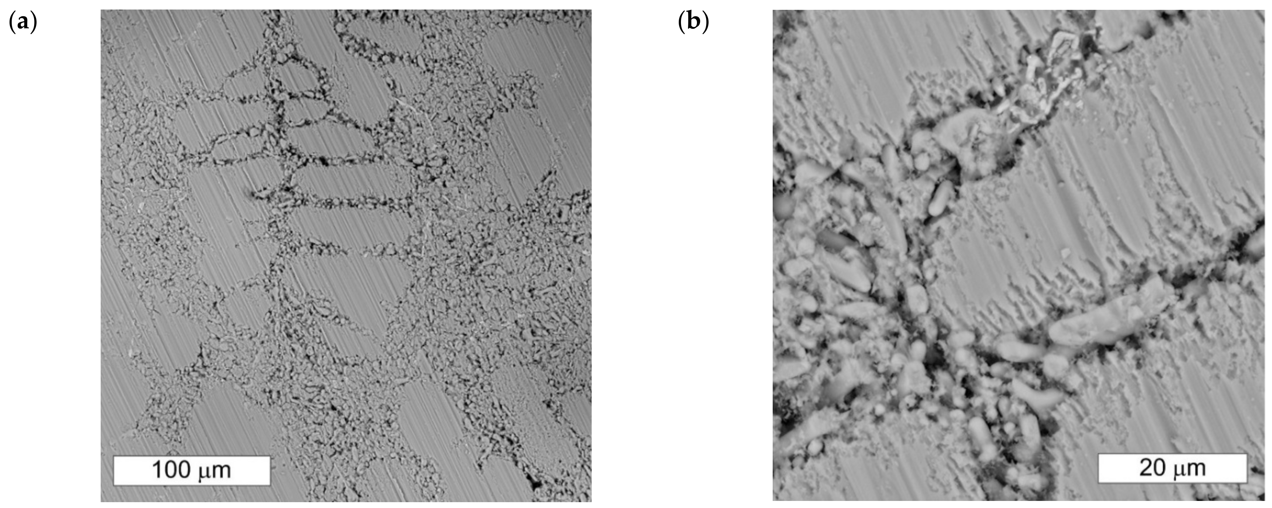
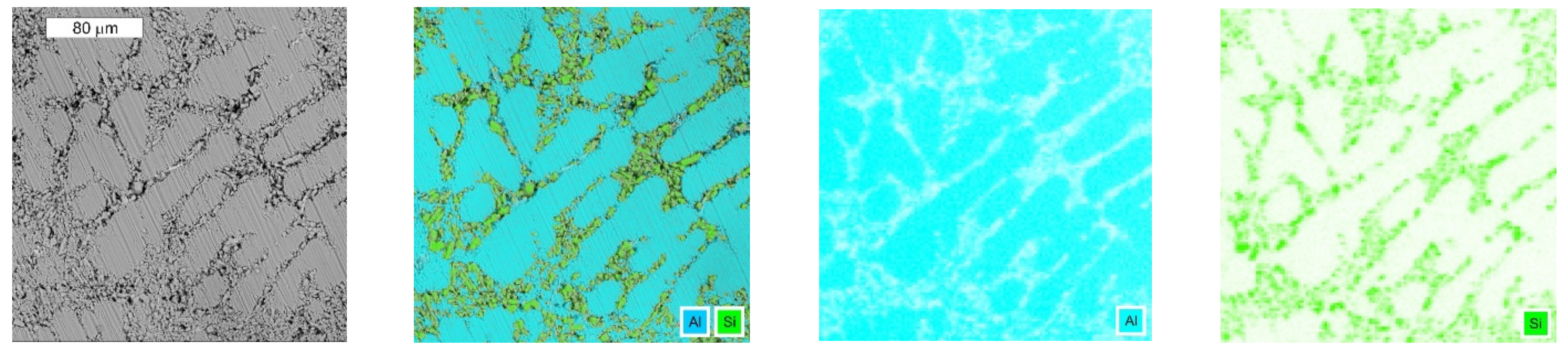
3.1. Microscopic Examination of Decommissioned Heat Exchangers

Figure 2 shows the microstructure of a brazed joint in a decommissioned heat exchanger made of AA3003 alloy designated as W1. The microstructure in the braze area was characteristic of unmodified silumins. The microstructure consisted of a needle-like eutectic (α-Si), next to which there were precipitates of the α-AlFeMnSi phase of cubic shape. The presence of the α-AlFeMnSi phase precipitates was determined by microanalysis of the chemical composition. The presence of iron-rich phases is typical for these materials, which was also confirmed in other works [1,14]. The photomicrographs show extensive corrosion in the area of the brazed joint without affecting the integrity of the joint. The linear and surface distributions of the elements obtained from this area indicate that the corrosive processes affected the brazed connection, not the parent material (Figure 3 and Figure 4). Tests carried out elsewhere in the joint show that the microstructure in the braze area is susceptible to localized corrosion. The corrosion initiation takes place in the subsurface area in the vicinity of the eutectic silicon crystals and then propagates deeper into the material (Figure 5). The morphological system of the eutectic structure ensuring its continuous disintegration creates convenient channels for corrosion propagation, as shown in the SEM image in Figure 6. Corrosion initiation begins at the interface. This favors the rapid spread of corrosion changes along the interface between phase α and silicon crystals. Further corrosion development in the area of the brazed joint can lead to loss of cohesion and mechanical separation of the fins and profiles, especially since the corrosion intensity can be high due to the large cathode area (brazened elements) in relation to the anode area (brazed joint).
A similar development of corrosion was observed on the W2 decommissioned exchanger; however, the corrosion is more advanced. The zone of occurrence of corrosion features in most cases covered the areas of entire brazed joints (Figure 7), which is related to its longer service life. The subject of the analysis was an air conditioning condenser, which was used in the car for 1 year and 10 months. In the area of the solder, an increased silicon content was observed, which confirms that the corrosion concerned only the area of the brazed connection (Figure 8). For comparison, the microscopic image of this area was compared with that obtained for the unused exchanger (Figure 9a). The linear distribution of silicon and aluminum obtained in this area confirms the presence of a brazed joint (Figure 9b).
In the case of the W3 exchanger, a clearly selective nature of corrosion was observed (Figure 10). The corrosion products formed in the corroded areas tend to form cracks, which allows further penetration of the corrosive environment and spread of corrosion to other areas. The obtained surface distributions of the elements allow us to conclude that the dissolution affects α phase areas, while the eutectic silicon precipitates remain intact (Figure 11). It was also found that the α-AlFeMnSi phase precipitation present in the brazed connection area did not undergo corrosion changes, which indicates their cathodic nature. Their surface remains smooth and devoid of any dissolution features (Figure 12).

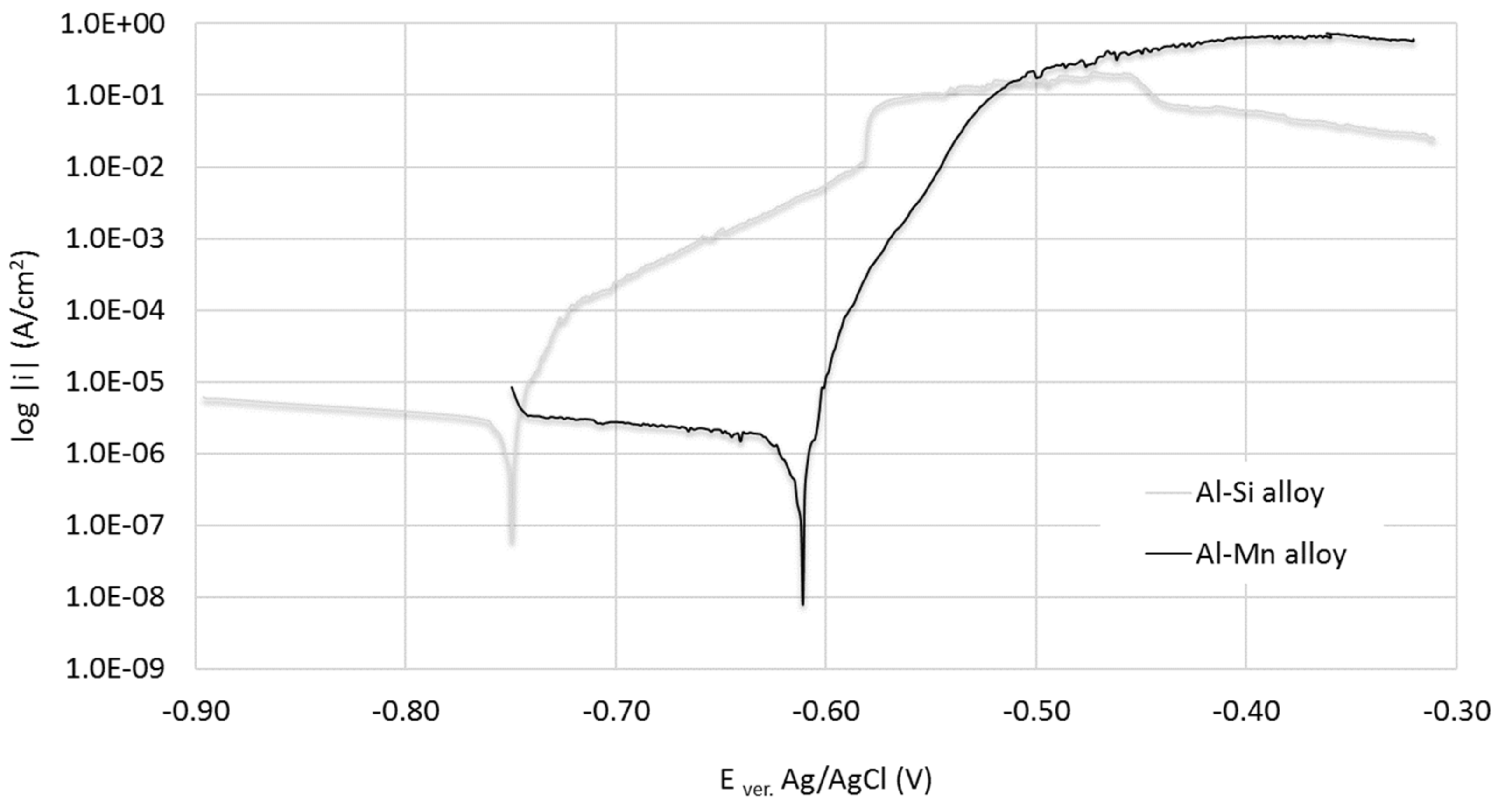
3.2. Electrochemical Test

The obtained results of metallographic tests carried out as part of the tests of the decommissioned exchangers indicate that the condition for the corrosion mechanism in the brazed joints is a galvanic cell. Due to this it was decided to perform electrochemical tests to obtain an answer to the question: What is the difference in corrosion potential between the joined materials? For this purpose, potentiodynamic tests of both alloys in a 5% NaCl solution were carried out, the purpose of which was to compare the electrochemical potentials of the materials used in the construction of the exchanger. Such a systemic approach will make it possible to compare the obtained results and verify the tests of decommissioned exchangers, which will contribute to a more complete assessment of corrosion phenomena occurring in these devices during operation. In this regard, it is important to describe the electrochemical interaction of the microstructure, with particular emphasis on the precipitates present in the matrix and their influence on corrosion. This will allow the assessment of the role of this microstructure on the mechanism of corrosion destruction of materials used in the construction of microchannel heat exchangers.
The first material for testing was EN AC-44000 grade silumin with the chemical composition presented in Table 3. Its silicon content is similar to the AW 4045 alloy used in brazing. Its microstructure was typical of Al-Si alloys. It consisted of α-Al(Si) solid solution dendrites against the background of the modified eutectic (α + Si)—Figure 13. The distribution of elements obtained from the microstructure area is shown in Figure 14. The presence of the iron-rich phase with a needle-like morphology indicates the presence of single precipitates of the β-AlFeSi phase in the microstructure. The second tested material was an aluminum–manganese alloy of EN AW3003 grade with the chemical composition also given in Table 3.
There is a belief that due to the use of only aluminum alloys in microchannel exchangers, the risk of galvanic corrosion is eliminated. Meanwhile, the tests carried out clearly indicate that they are not completely devoid of the risk of damage caused by bimetallic corrosion. The obtained polarization curves in electrochemical tests are shown in Figure 15, while the determined electrochemical parameters are presented in Table 4. On their basis, it was found that the difference in electrochemical potentials between these 3000 and 4000 series alloys in the tested corrosive solution is sufficient for the formation of a galvanic cell in the area of the brazed joint. Other authors also observed a lower value of the electrochemical potential for the Al-Si alloy [6]. The local nature of the changes occurring is also important, as is the small area of the anode surface, which may lead to the occurrence of intensive processes in the area of the brazed connection.
SEM microscopic examinations of the Al-Si alloy surface after electrochemical tests were carried out. The aim was to determine the mechanism of corrosion development in the braze area, which is the anode in the braze joints in question. It was found that the places of corrosion initiation were eutectic areas of the researched alloy (Figure 16 and Figure 17). The surface of the eutectic silicon particles remained smooth, without any traces of electrochemical interaction, which proves its cathodic interaction in relation to the matrix (Figure 16b). As a result of the formation of the galvanic microcell, phase α of the eutectic structure is particularly exposed to corrosion, which led to its preferential dissolution in the entire volume of the eutectic mixture. The distances between the cathode and the anode in the eutectic areas are small, which promotes corrosion. The conditions that occur during brazing, when the braze is melted without melting the materials to be joined, leads to the formation of a different microstructure than during conventional casting. This applies in particular to the presence of α-solid solution dendrites in the as-cast alloy used in electrochemical studies. In this latter case, corrosion developed in the eutectic areas, but also the solid solution dendrite regions were not completely free of corrosion features. The spread of corrosion was visible in the form of a crystallographic attack initiated at the interface between silicon crystals and the solid solution.
The cathodic nature of silicon crystals is also confirmed by other authors [22,23]. Zeng et al. [22] determined the value of the potential difference between the solid solution α and the silicon particles at the level of 180 mV. Yang et al. suggest [23] that the occurring corrosion is caused only by the galvanic interaction between the eutectic silicon crystals and the solid solution. They also note that the passive layer formed in the vicinity of silicon shows worse properties than the non-eutectic areas. The authors of the works [6,24] indicate the depletion of the matrix into silicon occurring around its precipitates. The formation of silicon-depleted zones around its precipitates should be combined with the short diffusion path of silicon occurring in eutectic regions. Dissolved silicon in aluminum affects the breakdown potential value making the aluminum nobler [24]. Thus, the silicon-depleted regions will have a lower standard potential. This leads to an increase in the potential difference between dendritic phase α and the eutectic, and consequently to a preferential dissolution of the α phase in the eutectic regions.

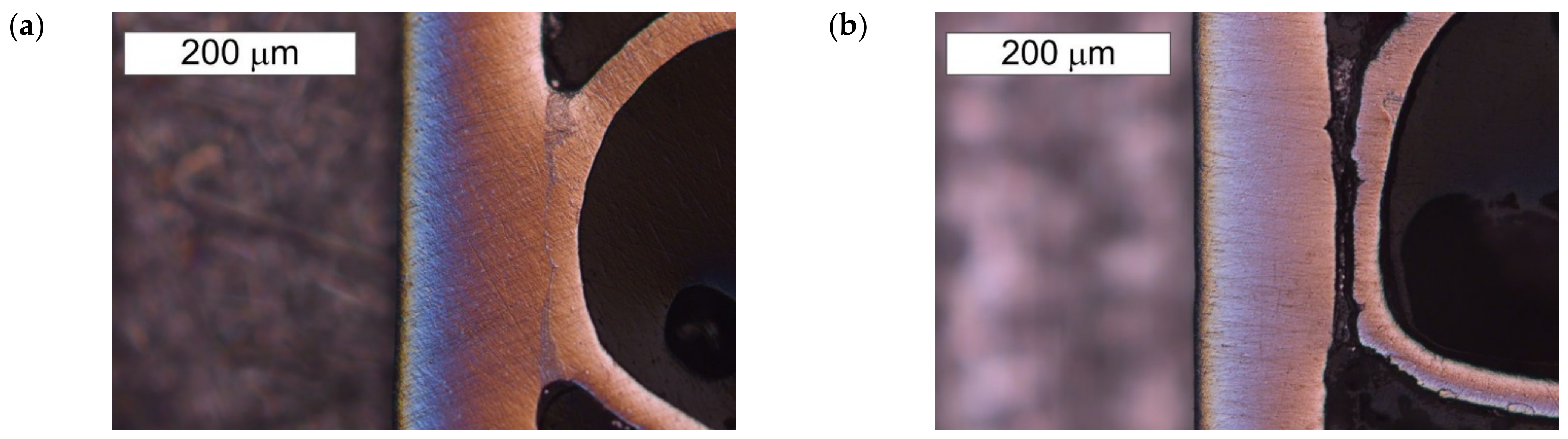
3.3. Microscopic Examination after the NSS Test

In order to confirm the results of electrochemical tests, metallographic tests of the unused exchanger (W4) were carried out before and after 120 h of the test in neutral salt spray (NSS test). The conducted test confirms the thesis concerning the galvanic interaction between the exchanger fins and the braze joint (Figure 18). After the tests carried out in neutral salt spray, extensive corrosion of the brazed joint is visible, occurring along its entire length. Meanwhile, in the area of the fins, surface unevenness, caused by the occurring corrosion processes, can be observed.

4. Conclusions

The tests carried out on the decommissioned exchangers, supported by the results of metallographic observations, allowed to conclude that a critical problem in the use of microchannel exchangers is galvanic corrosion occurring in the areas of brazed joints. These considerations were complemented by analyses carried out in laboratory conditions, which allowed the identification of the mechanisms of corrosion development. The verification of these observations obtained at the stage of examinations of the decommissioned exchangers was possible thanks to the assessment of the state of the surface after the influence of the corrosive factor in laboratory conditions.
The conducted tests showed that the Al-Si alloy used for brazing has a lower value of the corrosion potential than the core material. The existing potential difference is sufficient for galvanic corrosion. The electrochemical corrosion is initiated in the microcells formed in the microstructure of the alloy between the solid solution α and silicon crystals in eutectic structure. The solid solution in eutectic structure is the anode and is particularly susceptible to corrosion, which led to its preferential dissolution in the entire volume of the eutectic mixture.
The test and examination results carried out as part of the work confirm the advisability of using the approach in which the corrosion issues are supplemented with metallurgical issues, which allows one to predict the influence of microstructure on the corrosion behavior of various mechanical systems. At the same time, it is important that the analyses carried out on the decommissioned exchangers are verified on the basis of conclusions drawn at the stage of model laboratory tests. Such a hybrid approach usually requires the integration of different test and examination methods and their joint application.

Author Contributions

Conceptualization, M.M.L. and.; methodology, M.M.L. and M.B.L.; software, M.B.L.; validation, M.M.L.; formal analysis, M.M.L.; investigation, M.M.L. and M.B.L.; resources, M.B.L. and A.G.; writing—original draft preparation, M.M.L. writing—review and editing, M.M.L. and M.B.L.; visualization, M.M.L.; supervision, M.B.L.; project administration, M.B.L. and A.G.; funding acquisition, A.G. All authors have read and agreed to the published version of the manuscript.

Funding

This research received no external funding.

Data Availability Statement

Not applicable.

Conflicts of Interest

The authors declare no conflict of interest.

References

  1. Lachowicz, M.M.; Lachowicz, M.B.; Gertruda, A. Role of microstructure in corrosion of microchannel heat exchangers. Inżynieria Mater. Mater. Eng. 2018, 39, 94–99. [Google Scholar] [CrossRef]
  2. Lachowicz, M. Electrochemical and Microstructural Aspects of the Development of Corrosion Damage to Parts of Machines and Devices; Wydawnictwo Naukowe Instytutu Technologii i Eksploatacji—Sieć Badawcza Łukasiewicz: Radom, Poland, 2020. (In Polish) [Google Scholar]
  3. Venegas, T.; Qu, M.; Nawaz, K.; Wang, L. Critical review and future prospects for desiccant coated heat exchangers: Materials, design, and manufacturing. Renew. Sustain. Energy Rev. 2021, 151, 111531. [Google Scholar] [CrossRef]
  4. Zhao, L.H.; Wang, R.Z.; Ge, T.S. Desiccant coated heat exchanger and its applications. Int. J. Refrig. 2021, 130, 217–232. [Google Scholar] [CrossRef]
  5. Vivekh, P.; Kumja, M.; Bui, D.T.; Chua, K.J. Recent developments in solid desiccant coated heat exchangers—A review. Appl. Energy 2018, 229, 778–803. [Google Scholar] [CrossRef]
  6. Bordo, K.; Gudla, V.C.; Peguet, L.; Afseth, A.; Ambat, R. Electrochemical profiling of multi-clad aluminium sheets used in automotive heat exchangers. Corros. Sci. 2018, 131, 28–37. [Google Scholar] [CrossRef] [Green Version]
  7. Lacaze, J.; Tierce, S.; Lafont, M.C.; Thebault, Y.; Pébère, N.; Mankowski, G.; Blanc, C.; Robidou, H.; Vaumousse, D.; Daloz, D. Study of the microstructure resulting from brazed aluminium materials used in heat exchangers. Mater. Sci. Eng. A 2005, 413–414, 317–321. [Google Scholar] [CrossRef] [Green Version]
  8. Yoshino, M.; Iwao, S.; Edo, M.; Chiba, H. Mechanism of intergranular corrosion of brazed Al–Mn–Cu alloys with various Si content. J. Jpn. Inst. Light Met. 2017, 67, 234–241. [Google Scholar] [CrossRef] [Green Version]
  9. Peta, K.; Siwak, P.; Grochalski, K. Research on mechanical properties of aluminum alloys used in automotive industry. Inżynieria Mater. Mater. Eng. 2017, 38, 114–118. [Google Scholar] [CrossRef]
  10. Zhao, H.; Woods, R. 10—Controlled atmosphere brazing of aluminum. In Woodhead Publishing Series in Welding and Other Joining Technologies, Advances in Brazing; Sekulić, D.P., Ed.; Woodhead Publishing: Thorston, UK, 2013; pp. 280–323e. [Google Scholar] [CrossRef]
  11. Guia-Tello, J.C.; Pech-Canul, M.I.; Trujillo, E.; Pech-Canul, M. Effect of brazing parameters on fillet size and microstructure of cladded fin-microchannel tube joints. Trans. Nonferrous Met. Soc. China 2020, 30, 3240–3253. [Google Scholar] [CrossRef]
  12. Shutov, I.V.; Kamaeva, L.V.; Krivilyov, M.D.; Yu, C.N.; Mesarovic, S.D.; Sekulic, D.P. Effect of processing parameters on microstructure in brazing of Al–Si alloys. J. Cryst. Growth 2020, 530, 125287. [Google Scholar] [CrossRef]
  13. Guo, L.; Wang, J.; Hu, W.; Zhou, D. Corrosion Process of Multilayer Aluminum Brazed Sheet by EIS and EN Techniques. Surf. Rev. Lett. 2018, 26, 1850224. [Google Scholar] [CrossRef]
  14. Tierce, S.; Pébère, N.; Blanc, C.; Mankowski, G.; Robidou, H.; Vaumousse, D.; Lacaze, J. Solidification and phase transformations in brazed aluminium alloys used in automotive heat exchangers. Int. J. Cast Met. Res. 2005, 18, 370–376. [Google Scholar] [CrossRef]
  15. Yuan, Z.; Tao, F.; Wen, J.; Tu, Y. The Dependence of Microstructural Evolution and Corrosion Resistance of a Sandwich Multi-Layers Brazing Sheets on the Homogenization Annealing. IEEE Access 2019, 7, 121388–121394. [Google Scholar] [CrossRef]
  16. Marshall, G.J.; Bolingbroke, R.K.; Gray, A. Microstructural Control in an Aluminum Core Alloy for Brazing Sheet Applications. Metall. Mater. Trans. A 1993, 24, 1935–1942. [Google Scholar] [CrossRef]
  17. Yuan, Z.; Tu, Y.; He, H.; Yuan, T.; Zhang, Q.; Peng, X. Influence of final annealing temperature on the microstructural evolution and corrosion resistance of a Sandwich multi-layered aluminum sheet. Mater. Res. Express 2019, 6, 026536. [Google Scholar] [CrossRef]
  18. Kim, Y.S.; Park, I.J.; Kim, J.G. Simulation Approach for Cathodic Protection Prediction of Aluminum Fin-Tube Heat Exchanger Using Boundary Element Method. Metals 2019, 9, 376. [Google Scholar] [CrossRef] [Green Version]
  19. Ali, M.; Ul-Hamid, A.; Alhems, L.M.; Saeed, A. Review of common failures in heat exchangers—Part I: Mechanical and elevated temperature failures. Eng. Fail. Anal. 2020, 109, 104396. [Google Scholar] [CrossRef]
  20. Faes, W.; Lecompte, S.; Ahmed, Z.; Van Bael, J.; Salenbien, R.; Verbeken, K.; De Paepe, M. Corrosion and corrosion prevention in heat exchangers. Corros. Rev. 2019, 37, 131–155. [Google Scholar] [CrossRef]
  21. Lachowicz, M.M. A metallographic case study of formicary corrosion in heat exchanger copper tubes. Eng. Fail. Anal. 2020, 111, 104502. [Google Scholar] [CrossRef]
  22. Zeng, F.L.; Wei, Z.L.; Li, J.F.; Li, C.X.; Tan, X.; Zhang, Z.; Zheng, Z.Q. Corrosion mechanism associated with Mg2Si and Si particles in Al–Mg–Si alloys. Trans. Nonferrous Met. Soc. China 2011, 21, 2559–2567. [Google Scholar] [CrossRef]
  23. Yang, Y.; Chen, Y.; Zhang, J.; Gu, X.; Qin, P.; Dai, N.; Li, X.; Kruth, J.P.; Zhang, L.C. Improved corrosion behavior of ultrafine-grained eutectic Al-12Si alloy produced by selective laser melting. Mater. Des. 2018, 146, 239–248. [Google Scholar] [CrossRef]
  24. Oya, Y.; Kojima, Y.; Hara, N. Influence of Silicon on Intergranular Corrosion for Aluminum Alloys. Mater. Trans. 2013, 54, 1200–1208. [Google Scholar] [CrossRef]
Figure 1. Connection of fins with profiles in microchannel heat exchanger.
Crystals 12 01439 g001
Figure 2. (a) Corrosion of a brazed joint made of AA4045 alloy in the W1 microchannel heat exchanger, (b) Enlarged fragment from (a), SEM.
Crystals 12 01439 g002
Figure 3. Linear distribution of aluminum (green), silicon (blue) and manganese (yellow) obtained from the indicated area of the brazed joint (marked with an arrow). Visible increase in silicon content and decrease in aluminum content in the braze area, SEM/EDS.
Crystals 12 01439 g003
Figure 4. Microscopic image composed of the surface distribution of aluminum, oxygen and silicon (a), as well as the surface distribution of oxygen (b) and silicon (c) in the area shown in Figure 2, SEM/EDS.
Crystals 12 01439 g004
Figure 5. (a) Development of corrosion in the area of the brazed joint of the W1 exchanger in the area. Visible near-surface corrosion initiation progressing into the brazed joint. Intergranular corrosion is visible in the area of the fins. (b) Enlarged area from (a), SEM.
Crystals 12 01439 g005
Figure 6. (a) Development of corrosion in the area of the brazed connection of the W1 exchanger in the area of 2. (b) Eutectic structure disintegration creates convenient channels for corrosion propagation, SEM.
Crystals 12 01439 g006
Figure 7. (a) Extensive corrosion in the place where the brazed connection of the W2 exchanger occurs. (b) Enlarged fragment of the area from (a), SEM.
Crystals 12 01439 g007
Figure 8. Linear distribution of aluminum (green) and silicon (yellow) obtained from the indicated area of the brazed joint (marked with an arrow). Visible increase in silicon content and decrease in aluminum content in the area of corrosion, SEM/EDS.
Crystals 12 01439 g008
Figure 9. Brazed connection in the unused exchanger: (a) visible material continuity between the profile and the fin, (b) linear distribution of silicon (turquoise) and aluminum (yellow) confirming the presence of solder (this area is indicated by a solid line in (a), SEM/EDS.
Crystals 12 01439 g009
Figure 10. Development of corrosion in the brazed connection of the W3 exchanger. Visible near-surface corrosion initiation progressing deeper into the joint. Visible intergranular corrosion in the area of the fins: area 1 (a,b) and area 2 (c,d), SEM.
Crystals 12 01439 g010
Figure 11. Microscopic image of the brazed connection of the W3 exchanger in area 1 (a) with distribution of aluminum, silicon, and oxygen (b). Visible corrosion of solid solution α in eutectic areas (α + Si) with formation of corrosion products, SEM/EDS.
Crystals 12 01439 g011
Figure 12. (a) Microscopic image of the corroded area of the brazed connection of the W3 exchanger. Point 2 indicates the place where the microanalysis of the chemical composition was performed using the EDS method. (b) Spectrum of the characteristic X-ray radiation obtained from point 2 shown in the (a) in the place where the α-AlFeMnSi phase occurs, SEM/EDS.
Crystals 12 01439 g012
Figure 13. Microstructure of the tested silumin, grade EN AC-44000. Visible dendritic α phase precipitates with the eutectic (α + Si) and needle-like precipitates of the β-AlFeSi phase (white), SEM.
Crystals 12 01439 g013
Figure 14. Microscopic image of the silumin microstructure of the EN AC-44000 grade and the corresponding surface distribution of silicon and iron, SEM/EDS.
Crystals 12 01439 g014
Figure 15. Examples of potentiodynamic polarization curves obtained for the tested alloys from the Al-Si system typical for the braze area and Al-Mn typical for fins.
Crystals 12 01439 g015
Figure 16. (a) View of the surface of the AC 44000 alloy after electrochemical tests completed at a potential of +150 mV in relation to Ecorr (b) Magnified fragment of the area from the (a). Visible preferential dissolution of phase α in eutectic areas (α + Si) revealing modified silicon crystals, SEM.
Crystals 12 01439 g016
Figure 17. The microscopic image and the corresponding surface distribution of aluminum and silicon on the sample surface after electrochemical tests completed at a potential of +150 mV against Ecorr, SEM/EDS.
Crystals 12 01439 g017
Figure 18. Microscopic image of the brazed connection of the fin with the microchannel line of the W4 exchanger before the test (a) and after the test (b) in neutral salt spray. In the first case, the continuity of the brazed connection is visible, while the loss of its continuity along its entire length was observed after the test, light microscopy.
Crystals 12 01439 g018
Table 1. Chemical composition of the 3000 series aluminum alloys used in the construction of heat exchangers, in wt.%.
ALLOYMnFeSiCuZnMgCrAl
AW 30031.0 ÷ 1.5max. 0.70max. 0.600.05 ÷ 0.20max. 0.10--reszta
AW 31030.9 ÷ 1.5max. 0.70max. 0.50max. 0.10max. 0.20max. 0.30max. 0.10
AW 32031.0 ÷ 1.5max. 0.70max. 0.60max. 0.05max. 0.10--
Table 2. Chemical composition of the 4000 series aluminum alloys used for brazing heat exchangers, in wt.%.
ALLOYSiFeMnCuZnMgAl
AW 43436.8 ÷ 8.2max. 0.80max. 0.10max. 0.25max. 0.20-reszta
AW 41459.3 ÷ 10.7max. 0.80max. 0.153.3 ÷ 4.7max. 0.20max. 0.15reszta
AW 404711.0 ÷ 13.0max. 0.80max. 0.15max. 0.30max. 0.20max. 0.10reszta
AW 40459.0 ÷ 11.0max. 0.80max. 0.05max. 0.30max. 0.10max. 0.05reszta
Table 3. Chemical composition of tested aluminum alloys, in wt.%.
ALLOYSiFeCuMnMgZnAl
AC 4400010.40.150.010.010.350.02reszta
AW 30030.380.520.101.230.010.03reszta
Table 4. Electrochemical parameters obtained in 5% NaCl polarization tests for the tested alloys.
PARAMETERE0 (I = 0) (mV)Ecorr vs. Ag/AgCl
(mV)
icorr
(µA/cm2)
AC 44000−803 ± 6−750 ± 52.01 ± 0.4
AW 3003−633 ± 5−610 ± 30.93 ± 0.18
Publisher’s Note: MDPI stays neutral with regard to jurisdictional claims in published maps and institutional affiliations.

