Article

Optimal Polyethyleneimine Molecular Weight and Arrangement for Modification of γ-Cyclodextrin Metal Organic Frameworks (γ-CD-MOFs) for Post-Combustion CO2 Capture

1
Civil and Environmental Engineering Department, California Polytechnic State University, San Luis Obispo, CA 93407, USA
2
Materials Engineering Department, California Polytechnic State University, San Luis Obispo, CA 93407, USA
3
Industrial Technology and Packaging Department, California Polytechnic State University, San Luis Obispo, CA 93407, USA
*
Author to whom correspondence should be addressed.
Crystals 2022, 12(10), 1445; https://doi.org/10.3390/cryst12101445
Submission received: 1 September 2022 / Revised: 9 October 2022 / Accepted: 11 October 2022 / Published: 13 October 2022

Abstract

:
Modified γ-cyclodextrin metal organic frameworks (γ-CD-MOFs) are a promising eco-friendly sorbents for post-combustion CO2 capture. Polyethyleneimine (PEI) has been widely used for modifying MOFs to enhance their CO2 sorption capacity and selectivity through the introduction of CO2 selective amine groups. The main objective of this study was to determine the optimal PEI molecular weight and arrangement (linear or branched) to enhance γ-CD-MOF’s CO2 sorption capacity. γ-CD-MOFs were impregnated with linear as well as branched PEI with molecular weights of 600, 1200 or 10,000. The CO2 sorption capacity of the PEI-impregnated γ-CD-MOFs was determined using a quartz crystal microbalance assembly at CO2 partial pressures from 0.35–1.0 atm. Impregnation with 600 g/mole branched PEI achieved the highest CO2 sorption capacity of 0.9 mmole/g CO2 at 1 atm, followed by the linear PEI (0.12 mmol/g). Modification with the other branched PEI molecular weights did not achieve detectable CO2 sorption, likely because of pore blockage with the relatively larger PEI molecular weights, as demonstrated by molecular docking simulations. Furthermore, the control γ-CD-MOFs did not sorb CO2, likely because of the lower attraction forces between CO2 and the large pore volume of the unmodified MOFs.

1. Introduction

The upward trend in concentrations of greenhouse gases in the atmosphere is the main contributor to the ~1.0 °C increase in average global temperature compared to the pre-industrial levels [1]. This change in climate has already resulted in major environmental threats, which are only expected to escalate further if adequate measures are not implemented [2]. Carbon dioxide (CO2) and other greenhouse gases trap reflected infrared radiation from the Earth’s surface. This greenhouse effect leads to atmospheric warming, which accelerates rising sea levels, extreme weather events, food insecurity, and the spreading of diseases, among others [3]. Furthermore, CO2 dissolution in ocean waters lowered their pH by 0.10 since 1980, as reported by the National Oceanic and Atmospheric Administration (NOAA). Many carbonate-based organisms (e.g., coral reefs and mollusks) lose structural integrity in an acidic environment and thus, a decrease in these species has been predicted [4,5].
The ultimate solution for minimizing greenhouse gas emissions is the conversion to clean and sustainable energy sources. However, the current global energy demand exceeds the supply provided by existing renewable energy technologies, including solar, wind, hydro-power, and geothermal energy [6]. Therefore, in the short term, other strategies must be pursued concurrently with renewable technology development to achieve immediate and significant reductions in atmospheric CO2 concentrations. Carbon capture, from air and from point sources, is an attractive short-term approach to bridge the gap towards attaining carbon neutrality. Carbon capture is one of the key elements of several proposed frameworks for achieving carbon neutrality by 2050.
Carbon capture encompasses multiple methods for removing carbon dioxide from the atmosphere (i.e., direct air capture) or point sources. Carbon capture from point sources is a more cost-effective option compared to direct air capture because the concentrations of carbon dioxide in exhaust gas streams (e.g., 12–15% in coal-fired power plants) are drastically higher than CO2 concentrations in the atmosphere (<500 ppm) [7,8]. Approaches for carbon capture at the source include pre-combustion capture, oxyfuel combustion, and post-combustion capture [9]. Membrane filtration, liquid adsorption, and solid sorption are examples of the major post-combustion capture technologies [10]. Liquid adsorption using amine-based solutions (e.g., monoethanolamine (MEA)) has traditionally been the most utilized technology for post-combustion carbon capture [11]. However, the energy required for the regeneration of the liquid solvents is drastically higher than the regeneration of solid sorbents used for CO2 capture (e.g., activated carbon) [12]. This makes solid sorbents an attractive alternative for carbon capture applications.
Metal organic frameworks (MOFs), a novel class of solid sorbents, are promising candidates for CO2 capture. MOFs are comprised of metal nodes connected by organic linkage, resulting in a 3-D porous structure. Several types of MOFs have a higher surface-area-to-volume ratio than typically used sorption media, such as activated carbon. For example, the range of surface area of MOFs has been reported in the literature as 1000–10,000 m2/g [13]. In addition, MOFs have tunable properties through functionalization with numerous types of chemical agents to enhance their selectivity for target pollutants, among other applications [14].
MOFs synthesized using various types of metal nodes and organic linkages have been investigated to determine their CO2 sorption capacity. The results of these investigations show a broad range of CO2 sorption capacities, depending on the MOF characteristics and experimental conditions. For example, magnesium 2,5-dihydroxyterephthalate MOF (Mg-MOF-74) exhibited a relatively high sorption of 8.0 mmol CO2/g, while ZIF-100 MOF exhibited a much lower CO2 sorption capacity of 1.0 mmol/g [15,16,17]. The mechanisms of CO2 sorption on MOFs include Van Der Waals attraction forces between CO2 and the MOFs’ open metal sites and/or pores. The MOFs’ carbon dioxide sorption capacity is dependent upon the chemistry of the metal node, organic linkage, and functionalization agents (e.g., amine groups).
Post-combustion flue gas streams contain various types of gaseous molecules (e.g., N2 and SO2) as well as moisture (e.g., 6% H2O) [15]. Under typical flue gas conditions, the CO2 sorption performance of MOFs could be compromised. Exposure to moisture has been reported to cause hydrolysis and loss of structural integrity and, MOFs exhibit low CO2 selectivity in the presence of other gases [18]). For example, the 8.0 mmol CO2/g reported for Mg-MOF-74, would not likely be achieved in typical flue gas streams because Mg-MOF-74 is hydrophilic and undergoes hydrolysis in the presence of moisture [15]. In addition to the aforementioned limitations, synthesis of MOFs generally involves the use of different non-eco-friendly solvents (e.g., Dimethylformamide) and chemical precursors [19]. Thus, it would be ideal to develop more eco-friendly MOFs with high CO2 sorption capacity and selectivity under relevant flue gas conditions.
Cyclodextrin based MOFs are green materials derived from starch with a range of potential applications such as drug delivery, packaging, and CO2 capture [20]. Cyclodextrins are cyclic oligosaccharides with glucopyranose units linked by α-(1,4) bonds [20]. The classification of cyclodextrins is based on pore size and a number of glucopyranose units, as presented in Table 1. Cyclodextrin-based MOF structures consist of non-toxic cyclodextrin ligands linked by bio-compatible metal ions (e.g., K+, Ca2+, and Ti) [21].
Cyclodextrin MOFs are promising candidates for selective CO2 capture because of their relatively large pore size and high surface area to volume ratio that allows for the loading of functional groups selective for CO2. In addition, the hydrophobic nature of the inner cavity of cyclodextrin improves selectivity by minimizing the amount of flue gas moisture that could be captured in the pores [21]. The literature on cyclodextrin MOFs for CO2 capture is limited. The available investigations reported an average CO2 sorption of 1.4 mmol/g and 0.34 mmol/g for α-cyclodextrin and β-cyclodextrin MOFs, respectively [22,23].
Bare γ-cyclodextrin MOFs are not ideal for CO2 sorption applications as a result of their relatively large pore size. Van der Waals forces decrease as the pore size increases, resulting in less favorable sorption behavior [24]. These large pores can be reduced by adding compatible polymers. For example, the large pore sizes allow for the impregnation of selective polymer molecules for CO2 sorption. Specifically, polyethyleneimine (PEI) has been reported to increase the sorption capacity and selectivity of CO2 sorbent media [11]. PEI consists of a repeating amine group with two carbon aliphatic CH2-CH2 spacers, and has a wide range of molecular weights (e.g., 600–70,000 g/mol) and arrangements (i.e., linear and branched) [25]. PEI interacts with CO2 through a coupled amine group reaction to form a stable carbamate [26]. Functionalization or impregnation of PEI in MOFs can potentially increase the CO2 sorption capabilities and selectivity. For example, functionalization of MCM-41 MOF with PEI increased the sorption by 50x and increased the competitive selectivity in the presence of nitrogen [27].
The hypothesis of the current study was that γ-CD-MOFs can be converted into a selective CO2 solid sorbent through impregnation with PEI having an optimal molecular weight and arrangement. Impregnation with large polymeric molecules such as branched and linear PEI would reduce the pore size of the γ-cyclodextrin MOFs. This reduction in pore size will force CO2 molecules to pass through smaller voids, which will increase the Van der Waals attraction forces between CO2 and the MOFs. In addition, impregnation with Lewis basic amine functional groups will tune the γ-cyclodextrin MOF with CO2 selective properties. The main objective of this study was to determine the optimal PEI arrangement and molecular weight for use in CO2 sorption applications of γ-CD-MOFs. The research objectives was achieved through the following tasks: (1) synthesis, impregnation with linear and branched PEI with various molecular weights ranging from 600–70,000 g/mol, and characterization of γ-CD-MOFs, (2) quantification of the CO2 sorption capacity of each PEI-MOF combination using a Quartz Crystal Microbalance assembly, and (3) performing molecular docking simulations to verify the optimal molecular weight and arrangement that results in the highest CO2 sorption capacity.

2. Materials and Methods

2.1. Materials

Potassium hydroxide, methanol, dichloromethane, and γ-cyclodextrin were obtained from Fisher Scientific (Hampton, NH, USA). Branched polyethyleneimine (molecular weights 600, 1200, and 10,000) and linear polyethyleneimine were obtained from Thermo Fisher Scientific and Alfa Aesar (Haverhill, MA, USA), respectively. All chemicals were used without further purification. A single front load sensor, STM-2 oscillator, and 6 MHz gold crystals were purchased from INFICON Inc. (East Syracuse, NY, USA).

2.2. Synthesis of γ-CD MOFs

γ -CD MOFs were synthesized using the vapor diffusion method [28]. Potassium hydroxide (56.11 mg) and γ-cyclodextrin (163 mg) were dissolved in 5.0 mL deionized water. This solution was then transferred into a 10 mL open glass vial, which was placed in a 100.0 mL beaker filled with 50.0 mL of methanol and sealed with parafilm (Figure 1). This reactor setup was left for 14 days at room temperature until γ -CD MOFs were formed. Following formation, the solid MOFs were separated from the mixture by centrifugation at 3500 rpm for 5 min.
The produced γ-CD MOFs were washed three times with methanol to remove residual chemicals. Each wash was performed by mixing the MOFs with 5.0 mL of methanol and centrifuging the mixture for 5 min at 3500 rpm twelve hours later. The solid MOFs were then washed with 5 mL of dichloromethane (DCM) and centrifuged at 3500 rpm for 5 min. For activation, the MOFs were placed overnight under vacuum (~0.9 psi) in a 70 °C oven.

2.3. PEI Impregnation

Impregnation of γ-CD MOFs with PEI was carried out by dissolving 0.09 g of linear or branched (600 g/mol, 1200 g/mol, 10,000 g/mol) PEI in 5 mL methanol. The PEI solutions were sonicated for 5 min in an ultrasonic bath. Then, 0.10 g of γ-CD MOFs was added to each PEI solution and sonicated for an additional 5 min. The suspension was kept for 6 h at 70 °C. The PEI-impregnated MOFs were washed with methanol and then, activated under vacuum (~0.9 psi) in a 70 °C oven overnight.

2.4. Characterization of γ-MOF

Fourier-transform infrared spectroscopy (FTIR) was conducted for control and PEI-impregnated γ-CD MOFs samples using a Shimadzu (Columbia, MD, USA) IRAFFINITY-1S FTIR spectrometer mounted with a MIRacle10 ZnSe Attenuated Total Reflectance (ATR) assembly. The FTIR spectra were recorded using square triangle apodization with 45 scans at a resolution of 4 cm−1 across a range of 500–4000 cm−1. Thermogravimetric Analysis (TGA) was performed on samples (5–10 mg) of γ-CD MOF using a Q50 TGA from TA Instruments (New Castle, DE, USA). The samples were subjected to a temperature range of 23–600 °C with a heating ramp rate of 10 °C·min−1. The TGA testing was conducted under nitrogen purge gas with a balance purge flow of 40 mL·min−1 and a sample purge flow of 60 mL·min−1. Activated crystals of γ-CD-MOFs and γ-CD-MOFs impregnated with 600 MW BPEI were characterized using Rigaku Miniflex Diffractometer (Rigaku, TX, USA) with Cu radiation source at 40 kV. The samples were scanned and the data were collected in the range of 2 to 40° 2θ at 0.02 increments at a scan speed of 1.2° min−1 using incident beam 5.0°, receiving beam soller slit 5.0° and 1.25° divergent slit.

2.5. Experimental CO2 Sorption Quantification

2.5.1. CO2 Sorption Testing Apparatus

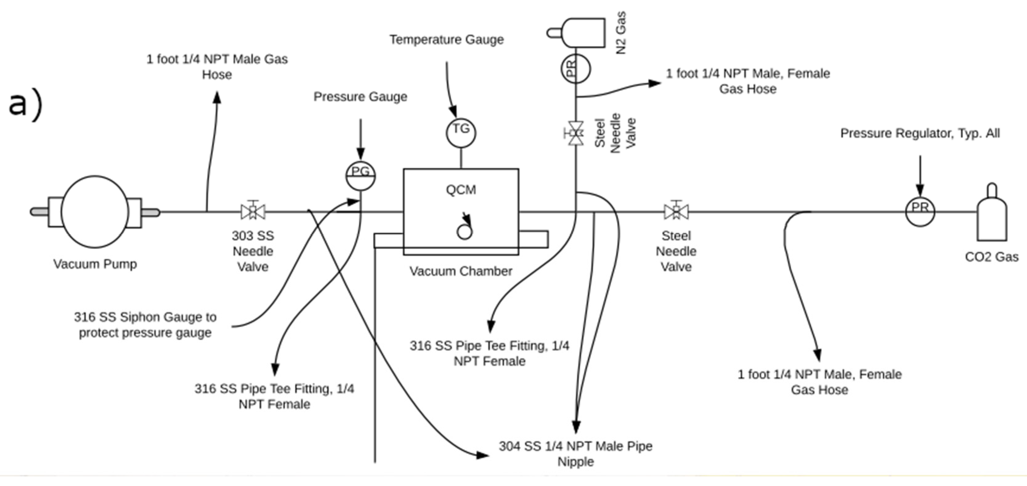
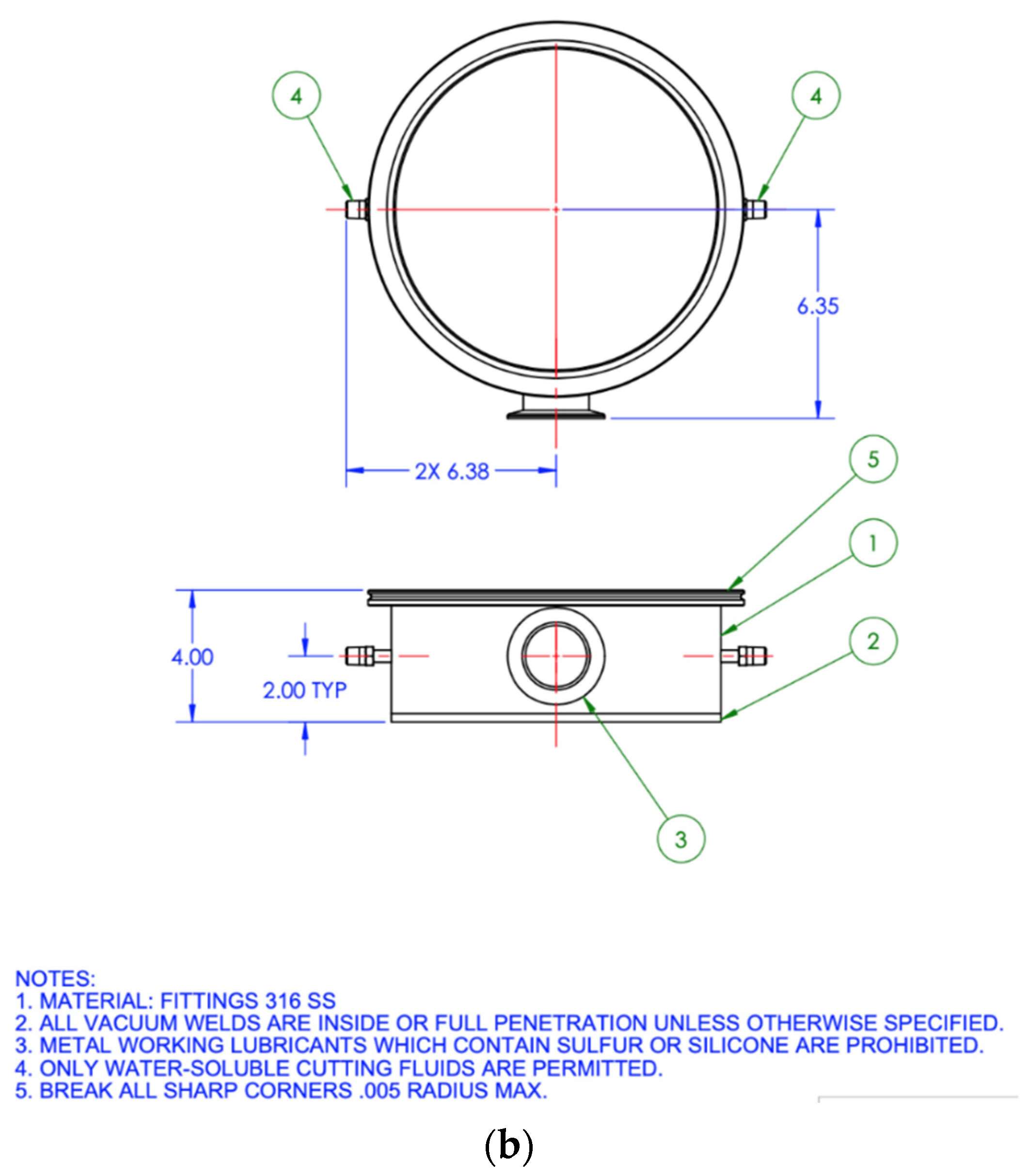
The CO2 sorption capacity was determined using a custom-built quartz crystal microbalance (QCM) assembly (Figure 2a). This assembly was a modified design of the apparatus developed by Hesketh et al. [28]. The QCM assembly consists of a front load single sensor, loaded with quartz crystals (6 MHz, gold electrode). The sensor is connected to a STM-2 oscillator/rate deposition monitor that is linked to the STM-2 software interface to monitor the frequency changes of the quartz crystal. A stainless-steel vacuum chamber (10 inch diameter and 4 inch height, NorCal USA) houses the QCM front load sensor and quartz crystal (Figure 2b). The vacuum chamber has two ports: one connects a vacuum pump to the outlet port and the other, connects a CO2 gas cylinder to an inlet port. The QCM assembly is equipped with vacuum gauges and needle valves to monitor and control the CO2 partial pressure inside the vacuum chamber.

2.5.2. CO2 Sorption Measurements

Before CO2 sorption testing, a reference quartz crystal (i.e., without MOFs) was cleaned with isopropyl alcohol and dried in a desiccator for 10 min. The reference crystal was then placed in the front load sensor of the QCM and held at maximum vacuum pressure (27.5 Hg) for 30 min to remove potential impurities and reach stable quartz crystal frequency. Next, CO2 gas was introduced to the vacuum chamber to achieve partial pressures ranging from 0.3 to 1.0 atm. The frequency of the reference crystal was recorded at each pressure point.
The reference crystal was removed from the chamber and loaded with γ -CD-MOFs using a drop casting method. This method included suspending 15 mg of γ -CD-MOFs in 5.0 mL of methanol and sonicating the mixture for 10 min. An 8 μL aliquot of the suspension was deposited on the crystal and allowed to dry in a desiccator for 30 min. The crystal carrying the deposited MOFs was re-loaded into the front sensor, and the frequency of the crystal was recorded at the aforementioned CO2 pressures. The Sauerbrey Equation (1) was then used to convert the difference in frequencies between the reference and the loaded crystal to a CO2 sorption capacity.
f m = 2 f 0 2 m A µ q ρ q
where f0 is the natural resting frequency, ∆fm is the change in frequency due to added mass, ∆m is mass deposited, A is the area (1.53 cm²), µq is the shear modulus (3.32 × 10⁻¹¹ dynes/cm²), and ρq is density (2.649 g/cm³) [29].

2.6. Molecular Docking Simulation

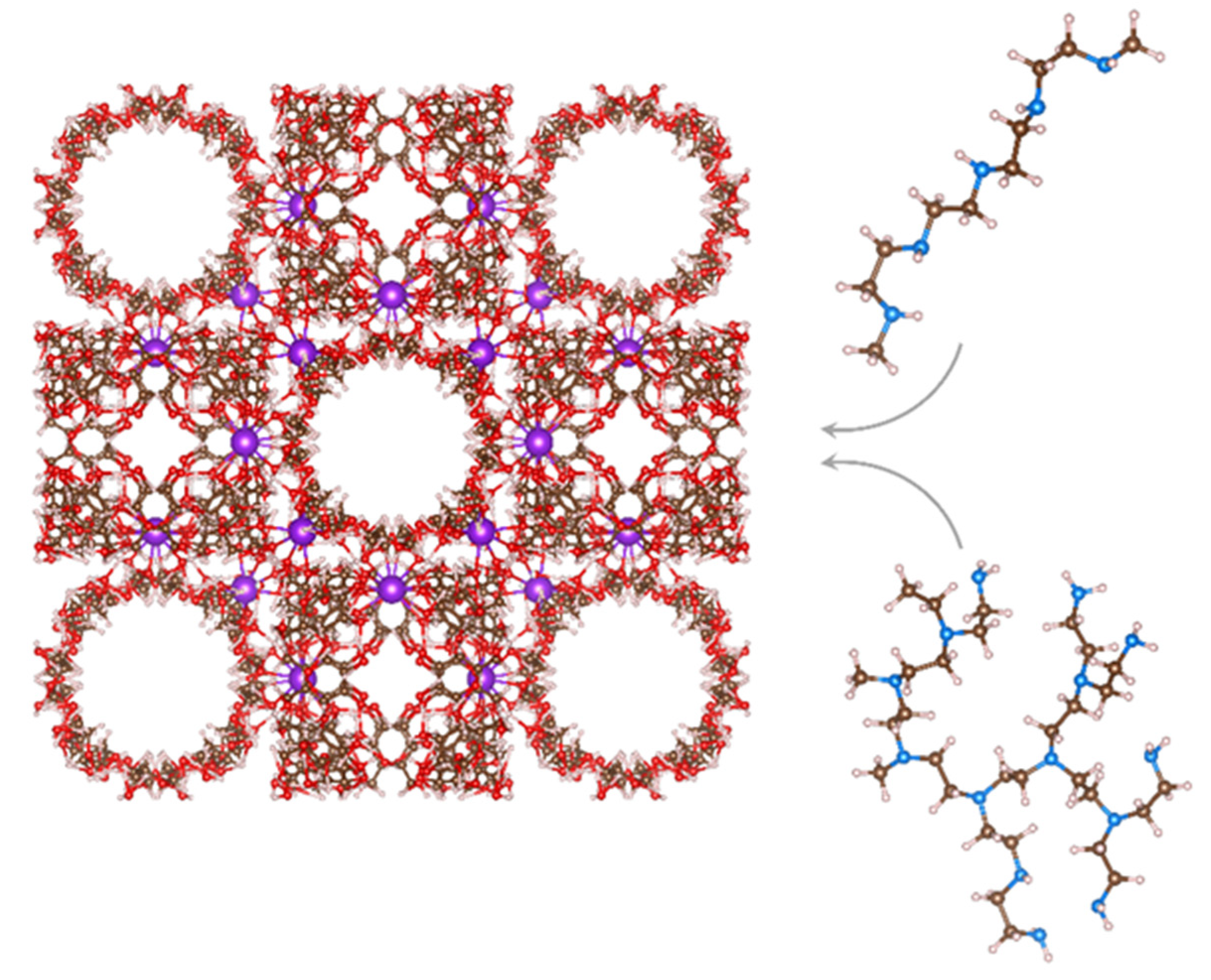
The structures of the linear and branched PEIs were modeled using the Avogadro program [30], while the structures of the γ-CD MOFs were obtained from the Cambridge Crystallography Data Center (CCDC). All structures were optimized using the molecular mechanics of the Avogadro program, and energy minimization calculations were performed to ensure the stability of the structures. Using AutoDock Tools [31], nonpolar hydrogen atoms of the γ-CD MOFs and PEI structures were merged, and only polar hydrogen atoms were considered. All rotatable bonds in PEI configurations were set to be rotatable, and Gasteiger charges were added. Four different arrangements of linear and branched PEI with various molecular sizes (representing various molecular weights) were docked onto the γ-CD MOFs, as schematically illustrated in Figure 3.
All molecular dockings were accomplished using AutoDock Vina [32] and only the most stable binding modes were considered. Because of the large size of the γ-CD MOF structure relative to the PEIs, and its various potential sites for encapsulation, molecular dockings were performed on the corner and the center of the γ-CD MOFs for each case. The molecular structure images were visualized by VESTA [31]. Electrostatic Potential (ESP) densities were calculated and illustrated using Arguslab software [33].

3. Results and Discussion

3.1. Impact of PEI Impregnation on γ-CD MOFs CO2 Sorption

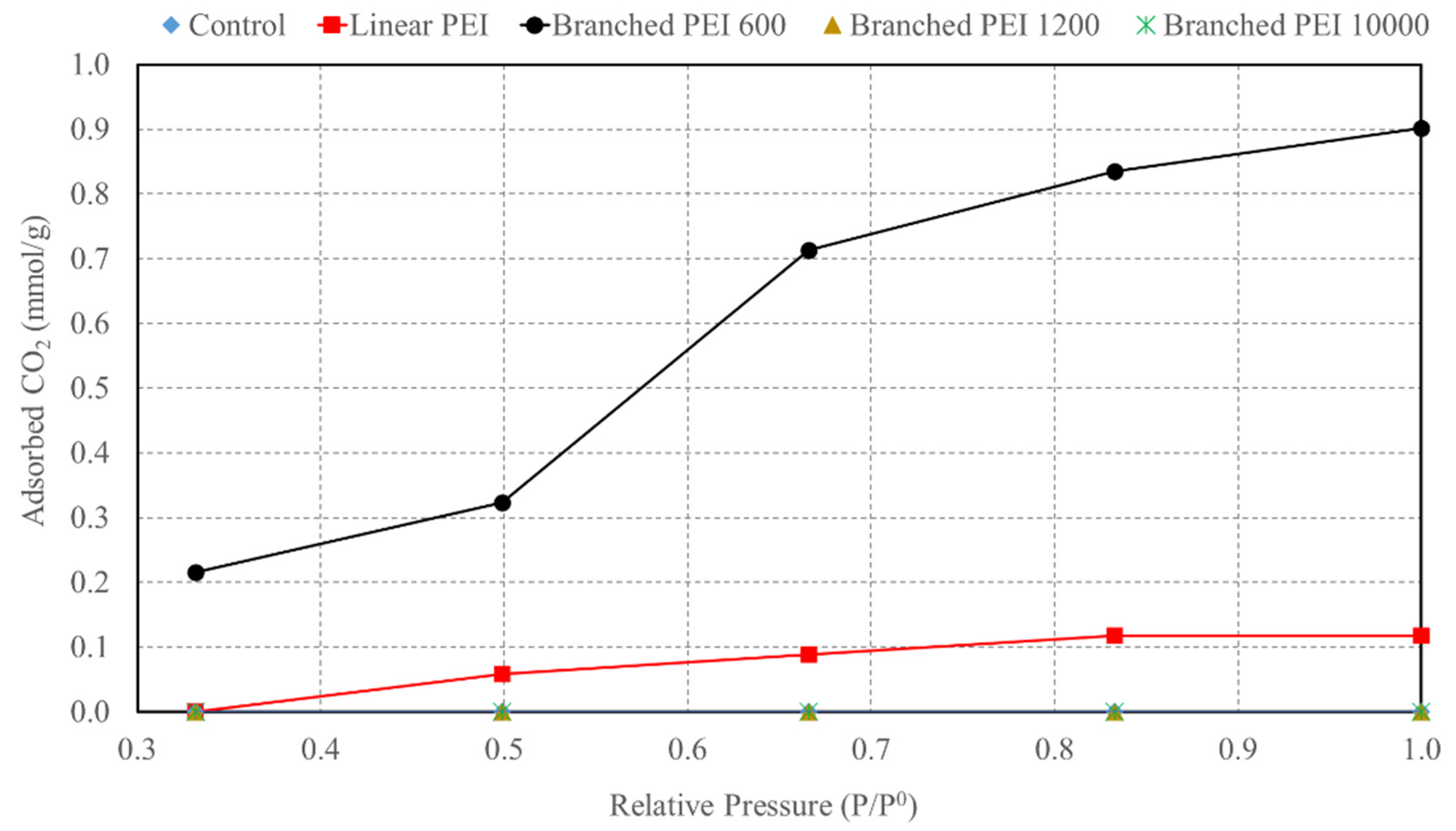
Figure 4 presents the amount of CO2 sorbed (mmol/g) as a function of influent CO2 partial pressure for γ-CD MOFs impregnated with different PEI arrangements and molecular weights. The γ-CD MOFs impregnated with linear PEI and 600 g/mole branched PEI (bPEI) exhibited CO2 sorption potential compared to the other tested MOFs (Figure 4). The γ-CD MOFs with 600 g/mol bPEI achieved the highest CO2 sorption profile with a maximum sorption capacity of 0.90 mmol/g at 1.0 atm. The second highest sorption profile was achieved by the γ-CD MOFs with linear PEI, which exhibited a drastically lower CO2 sorption of 0.12 mmol/g at 1.0 atm compared to 600 bPEI γ-CD MOFs at the same CO2 partial pressure. On the other hand, no CO2 sorption was observed for the control γ-CD MOFs, 1200 bPEI γ-CD MOFs, and 10,000 PEI γ-CD MOFs. It is possible that minimal amounts of CO2 were sorbed by these MOFs, but the sorption was below the detection capability of the QCM apparatus.
As hypothesized, the control γ-CD MOF did not sorb CO2 likely because of the large pore size, which lessens the magnitude of Van Der Waal attraction forces between CO2 and the pore surfaces of the MOFs. On the other extreme, the lack of CO2 sorption by the 1200 bPEI γ-CD MOF and 10,000 bPEI γ-CD MOF could be attributed to pore blockage as a result of relatively large molecular weight and branching of these PEI molecules. As the size of the PEI increased, the pores of the γ-CD MOFs were blocked. In other words, there is an optimum size of PEI molecules that can penetrate γ-CD MOF pores and higher Mw PEIs block pores which limit their CO2 sorption efficacy. Based on the results, it appears that the linear PEI and 600 bPEI had the proper size and arrangement to induce Lewis basic interactions between the CO2 and the amine groups of the PEI. In addition, the γ-CD-MOF pore narrowing by the PEI molecules likely increased Van Der Waals forces, which maximized the CO2 sorption potential of the linear- and 600 bPEI-γ-CD-MOFs. However, the 600 bPEI γ-CD-MOFs achieved higher CO2 sorption compared to the linear PEI γ-CD-MOFs. This higher CO2 sorption could be attributed to the branching arrangement of the 600 bPEI, which was probably more effective spatial distribution of the CO2 binding sites inside γ-CD-MOF pores compared to the linear PEI.
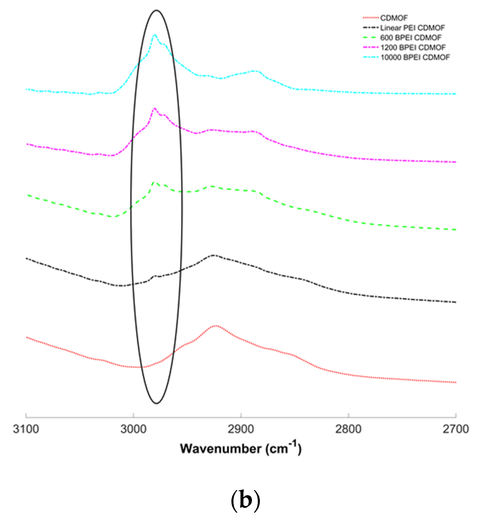
Furthermore, the FTIR and TGA characterization results provide evidence of possible interactions between the γ-CD-MOFs and the various PEI arrangements and molecular weights as well as elucidate the mechanism of CO2 sorption behavior discussed in Figure 4. The FTIR analysis showed a distinct peak at ~2980 cm−1 for all PEI-impregnated γ-CD MOFs compared to the control (Figure 5). PEI exhibits distinct peaks within the 2800–3500 cm−1 range that corresponds to n(NH) and n(CH) groups [34]. Therefore, the ~2980 cm−1 peak in Figure 5 could be attributed to the presence of the PEI on the surface of the MOFs. These FTIR results suggest that all types of PEI tested herein had some degree of interactions with the γ-CD-MOFs.
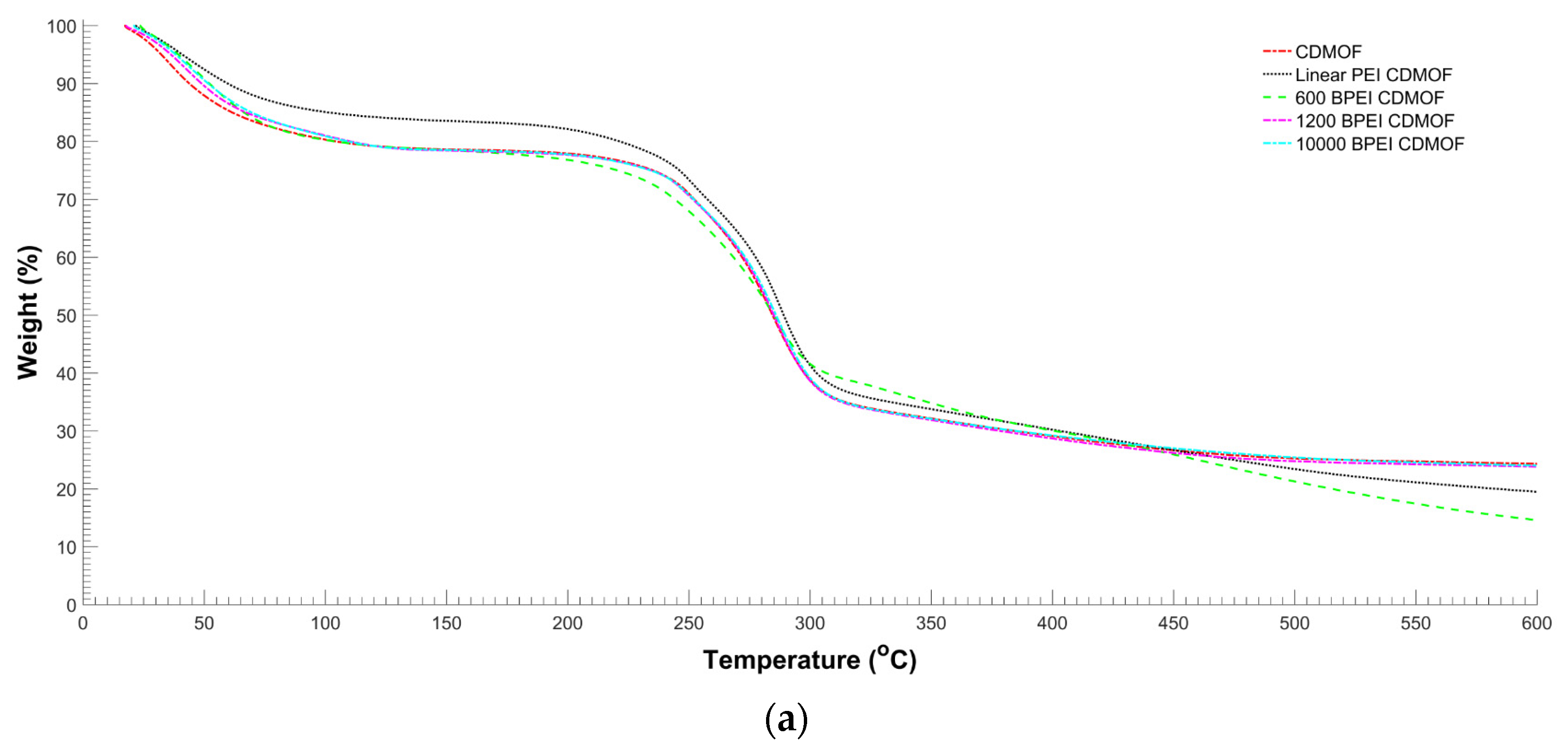
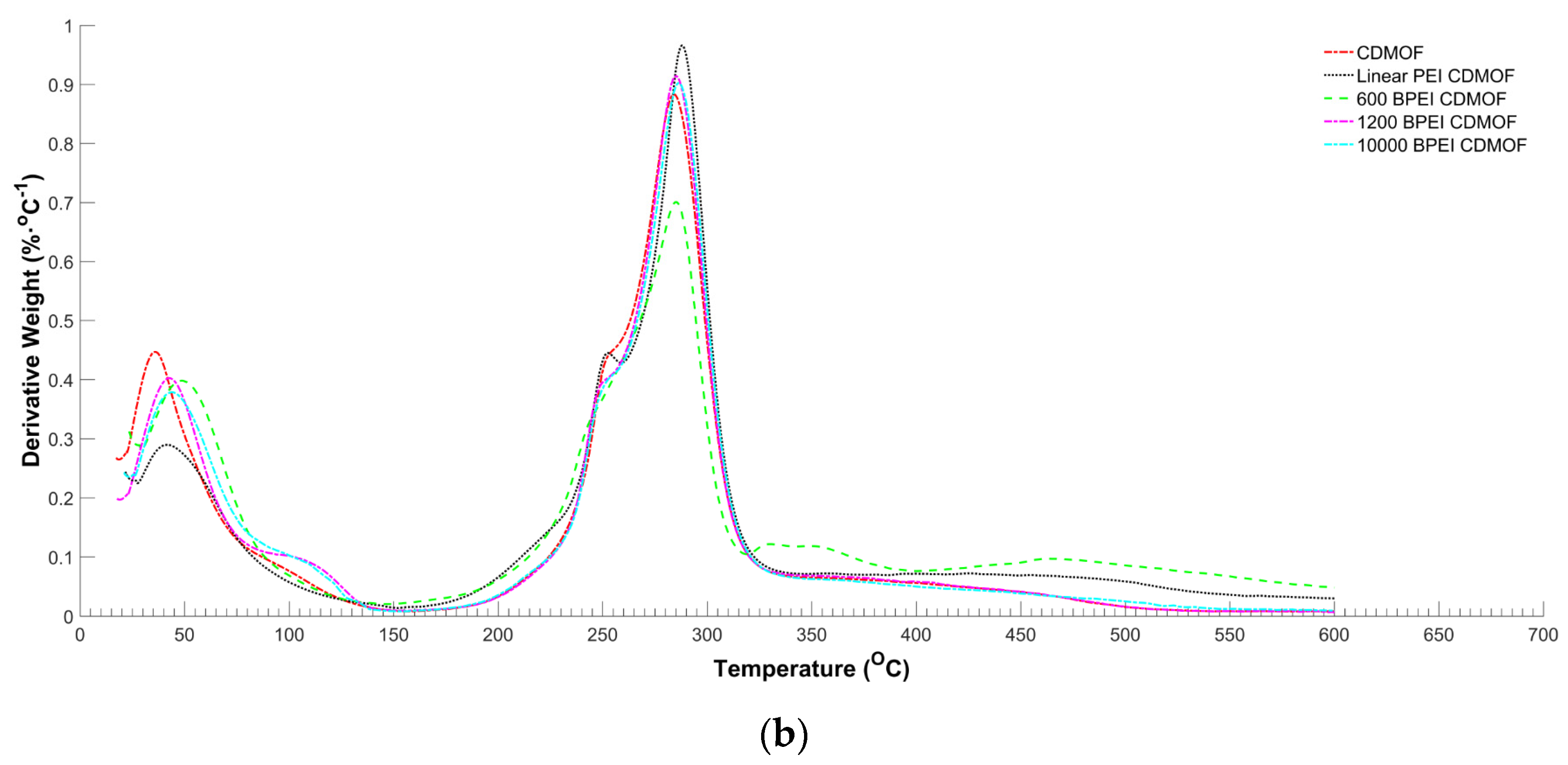
The TGA data presented in Figure 6 quantify the PEI-γ-CD-MOFs’ interactions with respect to the mass of PEI loaded onto the γ-CD-MOFs. The control-, 1200 bPEI-, and 10,000bPEI- γ-CD-MOFs exhibited a total weight loss of ~75% within the tested temperature range (0–600 °C) (Figure 6a). On the other hand, the 600 bPEI γ-CD MOFs had a total weight loss of ~84%, which means the PEI loading was approximately 11% (Figure 6a). The second highest loading achieved was ~6% in the case of linear PEI γ-CD MOFs (Figure 6a). The derivative profile of the mass change with temperature was plotted to identify temperatures at which peak weight losses occurred (Figure 6b). Above 300 °C, all the γ-CD-MOFs other than the linear PEI-γ-CD-MOFs and 600 bPEI-γ-CD-MOFs had identical TGA derivative profiles. The linear PEI-γ-CD-MOF and 600 bPEI-γ-CD-MOF had distinct percent weight loss peaks at 475 °C, and the 600 bPEI-γ-CD-MOF had an additional unique peak at 350 °C. These distinct peaks caused by the presence of the linear PEI and 600 bPEI molecules were observed in the cases of the γ-CD-MOFs that had detectable amounts of PEI loaded onto the MOFs, which differentiated them from the control MOFs derivative profile.
The CO2 sorption capacities of the γ-CD-MOFs tested strongly correlated with the amounts of PEI successfully loaded on MOFs as determined from the TGA data. Minimal CO2 sorption was achieved when PEI loading was negligible, as in the cases of 1200bPEI- and 10,000bPEI-γ-CD-MOFs. On the other hand, measurable CO2 sorption was achieved when the TGA detected PEI presence, as in the cases of linear- and 600 bPEI-γ-CD-MOFs. Specifically, the 600 bPEI-γ-CD-MOFs exhibited the highest CO2 sorption of 0.9 mmol/g with a 11% PEI loading. Following, the linear PEI-γ-CD-MOFs exhibited the second-highest CO2 sorption of 0.12 mmol/g with a PEI loading of 6%. Considering the results presented in this study, it appears that the 600 bPEI is a promising molecular arrangement and weight for modifying γ-CD-MOFs for enhanced CO2 capture applications. This further underscores the importance of future work to improve the impregnation method to achieve higher 600 bPEI loading onto γ-CD-MOFs. The CO2 sorption capacity achieved herein by the 600 bPEI- γ-CD-MOFs is approximately half the capacity of commonly used solid sorbents, such as activated carbon with a sorption capacity of 2.0 mmol/g [35]. The goal of future work would be to optimize the 600 bPEI loading onto the γ-CD-MOFs to achieve CO2 sorption capacity that markedly exceeds those of commercial solid sorbents.
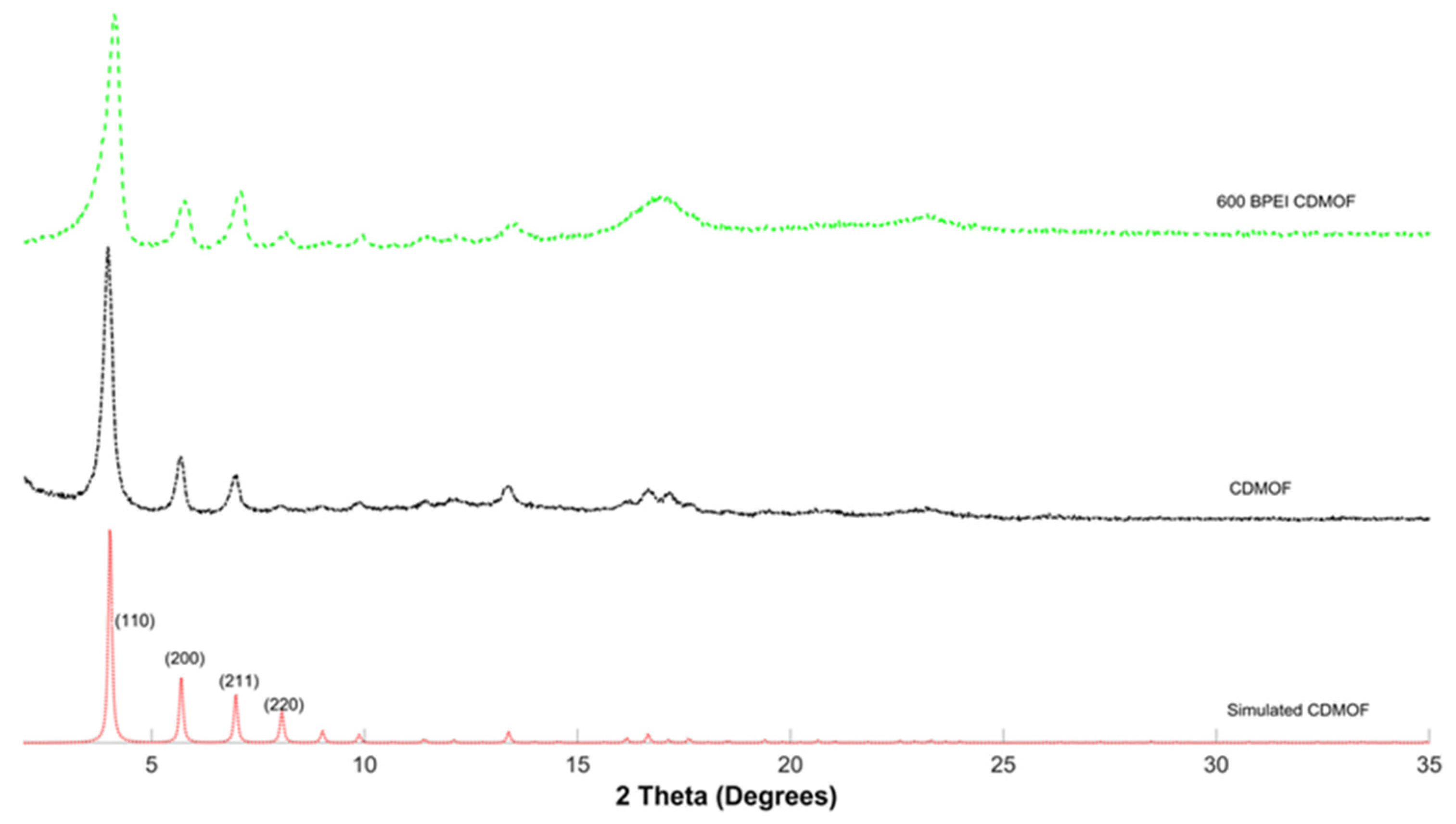
Figure 7 presents the simulated γ-CD-MOFs structure diffraction pattern and experimentally measured diffraction patterns of control γ-CD-MOFs and 600 bPEI-γ-CD-MOFs, which was the MOF that exhibited the highest CO2 adsorption capacity in this study. The diffraction patterns of the control γ-CD-MOFs and 600 bPEI-γ-CD-MOFs matched the simulated γ-CD-MOFs structure. These results indicate that the γ-CD-MOFs crystals retained crystal structure after impregnation with the 600 MW branched Polyethylenimine. Two additional broad peaks at 2 Theta ~ 18o and 24o were observed in the XRD patterns of the 600 bPEI-γ-CD-MOFs, which likely supports the presence of amorphous bPEI chains in the crystals.

3.2. Molecular Docking Simulations

Molecular docking was used to understand the molecular level interactions between various PEIs and the γ-CD-MOFs by studying the three-dimensional binding properties of PEI molecules with γ-CD-MOFs. The binding affinities were calculated for various binding modes (poses), and the most stable binding interactions (lowest binding affinities) were considered for comparison. Figure 8 presents the complex forms of the most stable docked structures and their binding energies. The first column from the left shows the encapsulation of linear PEI onto γ-CD-MOFs. The second through fourth columns illustrate the encapsulations of branched PEIs onto γ-CD-MOFs. From left (second column) to right (fourth column), the size, molecular weight, and complexity of the branched PEIs increase. The first row in Figure 8 shows the entire MOF with encapsulated PEIs, while the second and third rows show only the encapsulated portion of the MOF.
Linear PEI occupies the hydrophobic cavities between the two adjacent γ-CD rings in γ-CD-MOFs, and the most stable binding affinity was −3.2045 kcal/mol (Figure 8). This observation was consistent with previous studies of the molecular dockings on γ-CD-MOF [36,37,38]. The results for docking the branched PEIs showed a similar preference for the encapsulation site. However, docking the branched PEIs resulted in lower binding affinities (−3.6176 kcal/mol in the second column and −3.8176 kcal/mol in the third column) compared to the linear PEI docking (−3.2045 kcal/mol), showing stronger host-guest interactions between the γ-CD-MOF and low molecular weight branched PEIs. This can be explained by the molecular complexity of the branched PEIs with respect to the linear PEI. Multi-directional branches can produce more flexibility for the molecule to have a suitable pose (mode) in the encapsulation sites [39,40]. Moreover, the calculated electrostatic potential (ESP) densities showed that the branched PEI has more complex ESP densities, distributed along different directions (Figure 9). This increases the chances of the branched PEI molecules to have stronger and more stable bindings with the host γ-CD-MOF.
The lower binding affinity of the branched PEIs (second and third column in Figure 8) compared to that for linear PEI (first column in Figure 8), can explain the higher CO2 adsorption of the 600 bPEI-γ-CD-MOFs as compared to the linear PEI- γ-CD-MOFs (Figure 4). However, the molecular docking simulations showed that adding too many branches (increasing the molecular weights of the PEIs), shown in the fourth column of Figure 8, not only resulted in significantly higher binding affinities (less stable impregnation), but also the PEI molecule did not properly fit in its preferred binding sites. Figure 8 also shows that the larger PEI molecule in column 4 saturated both hydrophobic cavities between the two adjacent γ-CD rings and one of the γ-CD rings in the γ-CD-MOF. Therefore, the potential docking (impregnation) sites of the CD-MOF lost their ability to adsorb any more guests, resulting in the significantly low CO2 sorption predicted. Overall, the docking simulation results presented herein are in agreement with the experimental observations of the γ-CD-MOFs’ CO2 sorption as a function of PEI molecular weight and arrangement.

4. Conclusions

The objective of this work was to identify the optimal PEI molecular weight and arrangement to enable the eco-friendly γ-CD-MOFs for CO2 capture applications. The PEI tested were linear PEI, 600 bPEI, 1200 bPEI, and 10,000 bPEI. Due to their large pore size, the control γ-CD-MOFs expectedly did not show measurable CO2 sorption. Furthermore, impregnation of the γ-CD-MOFs with 1200 bPEI or 10,000 bPEI did not achieve detectable CO2 sorption likely because of their relatively large molecular weight that caused pore blockage as demonstrated by the molecular docking simulation results. On the other hand, impregnation with the linear or 600 bPEI unlocked the potential for CO2 capture by γ-CD-MOFs. The sorption capacities were 0.12 mmol/g and 0.90 mmol/g for linear PEI- γ-CD-MOFs and 600 bPEI- γ-CD-MOFs, respectively. The higher CO2 sorption achieved by the 600 bPEI-γ-CD-MOFs, compared to linear PEI-γ-CD-MOFs, could be explained by the higher loading percentage (11% for 600 bPEI and 6% for linear PEI) and the larger PEI molecular size in the case of 600 bPEI. Thus, among the polymers tested herein, the 600 bPEI was the ideal candidate for impregnation of γ-CD-MOFs for CO2 capture applications. However, future research is warranted to increase the 600 bPEI loading percentage so that the γ-CD-MOFs would achieve CO2 sorption capacities comparable to or exceeding those of commercial solid sorbents. In addition, characterization of possible changes to the γ-CD-MOFs after exposure to CO2 is needed to assess the reusability of the MOF for multiple cycles of CO2 sorption and studies are needed to test the selectivity of the MOF developed.

Author Contributions

Conceptualization, C.W., D.L. and A.E.B.; methodology, C.W., D.L., A.E.B., M.B.K. and A.K.; software, M.B.K.; validation, C.W. and A.E.B.; formal analysis, C.W., D.L., A.E.B. and M.B.K.; investigation, C.W. and D.L.; resources, A.E.B.; writing—original draft preparation, C.W., D.L., A.E.B., M.B.K. and A.K.; writing—review and editing, A.E.B., M.B.K. and A.K.; visualization, C.W.; supervision, A.E.B., M.B.K. and A.K.; project administration, A.E.B.; funding acquisition, A.E.B. All authors have read and agreed to the published version of the manuscript.

Funding

This research was partially funded by the CPConnect and Baker/Koob endowment programs at California Polytechnic State University.

Data Availability Statement

Not applicable.

Acknowledgments

The authors thank Professor Trevor Harding at California Polytechnic State University for providing access to materials characterization equipment.

Conflicts of Interest

The authors declare no conflict of interest.

References

  1. Kjellström, E.; Nikulin, G.; Strandberg, G.; Christensen, O.B.; Jacob, D.; Keuler, K.; Geert Lenderink, G.; Van Meijgaard, E.; Schär, C.; Somot, S.; et al. A Review on Contemporary Metal–Organic Framework Materials. Inorg. Chim. Acta 2016, 446, 61–74. [Google Scholar]
  2. Hoegh-Guldberg, O.; Jacob, D.; Taylor, M.; Guillén Bolaños, T.; Bindi, M.; Brown, S.; Camilloni, I.A.; Diedhiou, A.; Djalante, R.; Ebi, K.; et al. The human imperative of stabilizing global climate change at 1.5 C. Science 2019, 365, eaaw6974. [Google Scholar] [CrossRef] [Green Version]
  3. Parry, M.; Arnell, N.; McMichael, T.; Nicholls, R.; Martens, P.; Kovats, S.; Livermore, M.; Rosenzweig, C.; Iglesias, A.; Fischer, G. Millions at risk: Defining critical climate change threats and targets. Glob. Environ. Change 2001, 11, 181–183. [Google Scholar] [CrossRef]
  4. Orr, J.C.; Fabry, V.J.; Aumont, O.; Bopp, L.; Doney, S.C.; Feely, R.A.; Gnanadesikan, A.; Gruber, N.; Ishida, A.; Joos, F.; et al. Anthropogenic ocean acidification over the twenty-first century and its impact on calcifying organisms. Nature 2005, 437, 681–686. [Google Scholar] [CrossRef] [PubMed] [Green Version]
  5. Gazeau, F.; Parker, L.M.; Comeau, S.; Gattuso, J.P.; O’Connor, W.A.; Martin, S.; Pörtner, H.-O.; Ross, P.M. Impacts of ocean acidification on marine shelled molluscs. Mar. Biol. 2013, 160, 2207–2245. [Google Scholar] [CrossRef] [Green Version]
  6. Qazi, A.; Hussain, F.; Rahim, N.A.; Hardaker, G.; Alghazzawi, D.; Shaban, K.; Haruna, K. Towards sustainable energy: A systematic review of renewable energy sources, technologies, and public opinions. IEEE Access 2019, 7, 63837–63851. [Google Scholar] [CrossRef]
  7. Wang, X.; Song, C. Carbon capture from flue gas and the atmosphere: A perspective. Front. Energy Res. 2020, 8, 560849. [Google Scholar] [CrossRef]
  8. Hockstad, L.; Hanel, L. Inventory of US Greenhouse Gas Emissions and Sinks; (No. cdiac: EPA-EMISSIONS); US Department of Energy Office of Scientific and Technical Information: Oak Ridge, TN, USA, 2018. [CrossRef]
  9. Zhang, X.; Singh, B.; He, X.; Gundersen, T.; Deng, L.; Zhang, S. Post-combustion carbon capture technologies: Energetic analysis and life cycle assessment. Int. J. Greenh. Gas Control. 2014, 27, 289–298. [Google Scholar] [CrossRef] [Green Version]
  10. Chao, C.; Deng, Y.; Dewil, R.; Baeyens, J.; Fan, X. Post-combustion carbon capture. Renew. Sustain. Energy Rev. 2021, 138, 110490. [Google Scholar] [CrossRef]
  11. Dutcher, B.; Fan, M.; Russell, A.G. Amine-based CO2 capture technology development from the beginning of 2013—A Review. ACS Appl. Mater. Interfaces 2015, 7, 2137–2148. [Google Scholar] [CrossRef]
  12. Khraisheh, M.; Almomani, F.; Walker, G. Solid Sorbents as a Retrofit technology for CO2 Removal from natural Gas Under High pressure and temperature conditions. Sci. Rep. 2020, 10, 1–12. [Google Scholar] [CrossRef] [PubMed] [Green Version]
  13. Furukawa, H.; Cordova, K.E.; O’Keeffe, M.; Yaghi, O.M. The chemistry and applications of metal-organic frameworks. Science 2013, 341, 1230444. [Google Scholar] [CrossRef] [PubMed] [Green Version]
  14. Karmakar, A.; Velasco, E.; Li, J. Metal-organic frameworks (MOFs) as effective sensors and scavengers for toxic environmental pollutants. Natl. Sci. Rev. 2022. [Google Scholar] [CrossRef]
  15. Su, X.; Bromberg, L.; Martis, V.; Simeon, F.; Huq, A.; Hatton, T.A. Postsynthetic functionalization of Mg-MOF-74 with tetraethylenepentamine: Structural characterization and enhanced CO2 adsorption. ACS Appl. Mater. Interfaces 2017, 9, 11299–11306. [Google Scholar] [CrossRef]
  16. Caskey, S.R.; Wong-Foy, A.G.; Matzger, A.J. Dramatic tuning of carbon dioxide uptake via metal substitution in a coordination polymer with cylindrical pores. J. Am. Chem. Soc. 2008, 130, 10870–10871. [Google Scholar] [CrossRef] [PubMed]
  17. Wang, B.; Côté, A.P.; Furukawa, H.; O’Keeffe, M.; Yaghi, O.M. Colossal cages in zeolitic imidazolate frameworks as selective carbon dioxide reservoirs. Nature 2008, 453, 207–211. [Google Scholar] [CrossRef] [PubMed] [Green Version]
  18. Li, P.; Chen, J.; Zhang, J.; Wang, X. Water stability and competition effects toward CO2 adsorption on metal organic frameworks. Sep. Purif. Rev. 2015, 44, 19–27. [Google Scholar] [CrossRef]
  19. Kumar, S.; Jain, S.; Nehra, M.; Dilbaghi, N.; Marrazza, G.; Kim, K.H. Green synthesis of metal–organic frameworks: A state-of-the-art review of potential environmental and medical applications. Coord. Chem. Rev. 2020, 420, 213407. [Google Scholar] [CrossRef]
  20. Del Valle, E.M.M. Cyclodextrins and Their Uses: A Review. Process Biochem. 2004, 39, 1033–1046. [Google Scholar] [CrossRef]
  21. Rajkumar, T.; Kukkar, D.; Kim, K.H.; Sohn, J.R.; Deep, A. Cyclodextrin-metal–organic framework (CD-MOF): From synthesis to applications. J. Ind. Eng. Chem. 2019, 72, 50–66. [Google Scholar] [CrossRef]
  22. Ho, T.M.; Howes, T.; Bhandari, B.R. Encapsulation of CO2 into amorphous and crystalline α-cyclodextrin powders and the characterization of the complexes formed. Food Chem. 2015, 187, 407–415. [Google Scholar] [CrossRef] [Green Version]
  23. Guo, T.X.; Bedane, A.H.; Pan, Y.; Xiao, H.; Eić, M. Characteristics of carbon dioxide gas adsorption on β-cyclodextrin derivative. Mater. Lett. 2017, 189, 114–117. [Google Scholar] [CrossRef]
  24. Kathuria, A.; Pauwels, A.K.; Buntinx, M.; Shin, J.; Harding, T. Inclusion of ethanol in a nano-porous, bio-based metal organic framework. J. Incl. Phenom. Macrocycl. Chem. 2019, 95, 91–98. [Google Scholar] [CrossRef]
  25. Shen, X.; Du, H.; Mullins, R.H.; Kommalapati, R.R. Polyethylenimine applications in carbon dioxide capture and separation: From theoretical study to experimental work. Energy Technol. 2017, 5, 822–833. [Google Scholar] [CrossRef] [Green Version]
  26. Xian, S.; Xu, F.; Ma, C.; Wu, Y.; Xia, Q.; Wang, H.; Li, Z. Vapor-enhanced CO2 adsorption mechanism of composite PEI@ ZIF-8 modified by polyethyleneimine for CO2/N2 separation. Chem. Eng. J. 2015, 280, 363–369. [Google Scholar] [CrossRef]
  27. Le, M.U.T.; Lee, S.Y.; Park, S.J. Preparation and characterization of PEI-loaded MCM-41 for CO2 capture. Int. J. Hydrogen Energy 2014, 39, 12340–12346. [Google Scholar]
  28. Yan, T.K.; Nagai, A.; Michida, W.; Kusakabe, K.; binti Yusup, S. Crystal growth of cyclodextrin-based metal-organic framework for carbon dioxide capture and separation. Procedia Eng. 2016, 148, 30–34. [Google Scholar] [CrossRef] [Green Version]
  29. Venkatasubramanian, A.; Navaei, M.; Bagnall, K.R.; McCarley, K.C.; Nair, S.; Hesketh, P.J. Gas Adsorption characteristics of metal–organic frameworks via quartz crystal microbalance techniques. J. Phys. Chem. C 2012, 116, 15313–15321. [Google Scholar] [CrossRef]
  30. Hanwell, M.D.; Curtis, D.E.; Lonie, D.C.; Vandermeersch, T.; Zurek, E.; Hutchison, G.R. Avogadro an advanced semantic chemical editor, visualization, and analysis platform. J. Cheminform. 2012, 4, 17. [Google Scholar] [CrossRef] [Green Version]
  31. Morris, G.M.; Huey, R.; Lindstrom, W.; Sanner, M.F.; Belew, R.K.; Goodsell, D.S.; Olson, A.J. Auto dock 4 and auto dock tools 4: Automated docking with selective receptor flexibility. J. Comput. Chem. 2010, 30, 2785–2791. [Google Scholar] [CrossRef] [Green Version]
  32. Trott, O.; Olson, A.J. AutoDock Vina: Improving the speed and accuracy of docking with a new scoring function, efficient optimization and multithreading. J. Comput. Chem. 2010, 31, 455–461. [Google Scholar] [CrossRef]
  33. Thompson, M.A. Molecular Docking Using ArgusLab, an Efficient Shape-Based Search Algorithm and the a Score Scoring Function. In Proceedings of the American Chemical Society—228th National Meeting, Philadelphia, PA, USA, 22–26 August 2004. [Google Scholar]
  34. Xin, Q.; Ouyang, J.; Liu, T.; Li, Z.; Li, Z.; Liu, Y.; Wang, S.; Wu, H.; Jiang, Z.; Cao, X. Enhanced interfacial interaction and CO2 separation performance of mixed matrix membrane by incorporating polyethylenimine-decorated metal–Organic frameworks. ACS Appl. Mater. Interfaces 2015, 7, 1065–1077. [Google Scholar] [CrossRef]
  35. Rashidi, N.A.; Yusup, S.; Loong, L.H. Kinetic studies on carbon dioxide capture using activated carbon. Chem. Eng. Trans. 2013, 35, 361–366. [Google Scholar]
  36. Momma, K.; Izumi, F. VESTA 3 for three-dimensional visualization of crystal, volumetric and morphology data. J. Appl. Crystallogr. 2011, 44, 1272–1276. [Google Scholar] [CrossRef]
  37. Zhang, B.; Huang, J.; Liu, K.; Zhou, Z.; Jiang, L.; Shen, Y.; Zhao, D. Biocompatible cyclodextrin-based metal-organic frameworks for long-term sustained release of fragrances. Ind. Eng. Chem. Res. 2019, 58, 19767–19777. [Google Scholar] [CrossRef]
  38. He, Y.; Zhang, W.; Guo, T.; Zhang, G.; Qin, W.; Zhang, L.; Wang, C.; Zhu, W.; Yang, M.; Hu, X.; et al. Drug nanoclusters formed in confined nano-cages of CD-MOF: Dramatic enhancement of solubility and bioavailability of azilsartan. Acta Pharm. Sin. B 2019, 9, 97–106. [Google Scholar] [CrossRef]
  39. Kathuria, A.; Harding, T.; Auras, R.; Kivy, M. Encapsulation of hexanal in biobased cyclodextrin metal organic framework for extended release. J. Incl. Phenom. Macrocycl. Chem. 2021, 101, 121–130. [Google Scholar] [CrossRef]
  40. Chen, L.; Watanabe, T.; Kanoh, H.; Hata, K.; Ohba, T. Cooperative CO2 adsorption promotes high CO2 adsorption density over wide optimal nanopore range. Adsorpt. Sci. Technol. 2018, 36, 625–639. [Google Scholar] [CrossRef]
Figure 1. Schematic representation of vapor diffusion synthesis method of γ-CD-MOF.
Crystals 12 01445 g001
Figure 2. Quartz crystal microbalance assembly for testing CO2 sorption (a) full system schematic and (b) stainless steel vacuum chamber dimensions (Nor Cal Products Inc., Siskiyou County, CA, USA).
Crystals 12 01445 g002aCrystals 12 01445 g002b
Figure 3. Schematic representation of encapsulation of linear and branched PEI in porous γ-CD MOF structure. Atoms of H, C, O, N and K are shown as pink, brown, red, blue and purple, respectively.
Crystals 12 01445 g003
Figure 4. Impact of PEI arrangements and molecular weights on CO2 sorption behavior of γ-CD MOFs.
Crystals 12 01445 g004
Figure 5. FTIR spectra of control and PEI loaded γ-CD-MOFs, (a) entire spectra and (b) the region of 2800–3100 cm−1 wavenumber on the FTIR spectra to clearly capture the details of this range.
Crystals 12 01445 g005aCrystals 12 01445 g005b
Figure 6. TGA data for control and PEI loaded γ-CD-MOFs (a) TGA Thermogram, and (b) Derivative profile of the tested PEI-γ-CD-MOFs combinations.
Crystals 12 01445 g006aCrystals 12 01445 g006b
Figure 7. XRD data for simulated cyclodextrin MOF as well as control γ-CD-MOFs and 600 bPEI-γ-CD-MOFs.
Crystals 12 01445 g007
Figure 8. Complex structures of the PEIs and γ-CD-MOF. The first column from left is for the docking of linear PEI, while the other three columns are for branched PEIs. The complexity and molecular sizes of the branched PEIs increase from left to right. Atoms of H, C, O, N and K are shown as pink, brown, red, blue and purple, respectively.
Crystals 12 01445 g008
Figure 9. Calculated ESP density maps for linear (left) and branched (right) PEIs.
Crystals 12 01445 g009
Table 1. Cyclodextrin Characteristics [20,21].
CyclodextrinPore Size (nm)Number of Glucopyranose Units
α-cyclodextrin0.576
β-cyclodextrin0.787
γ-cyclodextrin0.958
Publisher’s Note: MDPI stays neutral with regard to jurisdictional claims in published maps and institutional affiliations.