Article

Effect of Load and Fiber Orientation on Wear Properties of Additively Manufactured Continuous CFRP Composites under Dry Sliding Conditions

by
Mahesh Naik
1,
Dineshsingh G. Thakur
1,
Sunil Chandel
1,
Sachin Salunkhe
2,* and
Hussein Mohamed Abdelmoneam Hussein
3,4
1
Department of Mechanical Engineering, Defence Institute of Advanced Technology (DU), Pune 411025, India
2
Department of Mechanical Engineering, Veltech Rangarajan Dr. Sagunthala R & D Institute of Science and Technology, Chennai 600062, India
3
Mechanical Engineering Department, Faculty of Engineering and Technology, Future University in Egypt, New Cairo 11835, Egypt
4
Mechanical Engineering Department, Faculty of Engineering, Helwan University, Cairo 11732, Egypt
*
Author to whom correspondence should be addressed.
Crystals 2022, 12(10), 1481; https://doi.org/10.3390/cryst12101481
Submission received: 30 July 2022 / Revised: 21 August 2022 / Accepted: 3 September 2022 / Published: 19 October 2022

Abstract

:
The present research investigates the wear properties of a continuous carbon fiber-reinforced additively manufactured polymer composite under dry sliding conditions. The effect of load and fiber orientation is examined on polymer composite specimens. The wear test of the additively manufactured polymer composite specimens is conducted on pin-on-disk test equipment. The result shows that the applied load and fiber orientation significantly affect the composite specimen’s wear properties. The wear and coefficient of friction (COF) increase with load. The minimum effect on wear and COF is observed for 0° fiber orientation, and the maximum effect is observed for 90° fiber orientation. Finally, morphological analysis is conducted using an optical micrograph of the worn-out surfaces to understand the failure type for different fiber orientations.

1. Introduction

Additive manufacturing (AM) is a vital manufacturing technology for fabricating metallic and polymer parts. Fused deposition modelling (FDM), among the other AM processes, has gained popularity for fabricating polymer parts. Due to their low cost and light weight, polymers are primarily used in applications, i.e., shaft seals, gears, bushes, sliding bearings, and electrical applications [1,2,3,4,5]. The use of polymers alone has resulted in limited applications. The reinforcement of fibers can further increase the application of polymers. The reinforcement of fibers in the polymer matrix leads to modifications of tribological, thermal, and mechanical properties [6,7]. Many polymer composites are used in dry conditions because they offer less frictional resistance to sliding. In many fields, the application of polymer composites has increased as an end product, leading to the increased study of the friction and wear of polymer composites.
Most of the research was found to investigate the effect of process variables (such as load, speed, sliding distance, and temperature) on the tribological properties of polymer composites. Zao et al. (2015) [8] investigated the wear and friction properties of the polyimide reinforced with carbon, glass, and aramid fibers at higher temperatures under sliding and erosive conditions. They reported that the wear rate increases as the temperature rises. Xu et al. (2010) [9] examined the effect of load and sliding velocity on the wear properties of PA1010 polymer reinforced with aramid fiber. They reported that the wear resistance increases and the coefficient of friction (COF) decreases with aramid fiber reinforcement in PA1010. Sharma et al. (2009) [10] investigated the effect of fiber orientation concerning sliding direction on the tribological behavior of unidirectional carbon fiber-reinforced polyetherimide polymer. They reported that with increases in the fiber orientation angle from 0° to 90°, the wear properties of the composite deteriorate. Stanley et al. (2021) [11] investigated the abrasive wear properties of glass fiber/methyl methacrylate resin composites fabricated using the vacuum infusion process. To enhance the fiber/matrix interface and composite properties, cellulose microcrystals were added to the resin. They concluded that the wear performance is improved by 22.27% by adding 1% CMC to the composites. Chavali and Taru (2020) [12] investigated the wear properties of banana fiber-reinforced composite at various fiber orientations (0°, 15°, 45°, 75°, and 90°) and load (20 N and 50 N). They reported that the wear increases as the load and fiber orientation angle increases. Lasikun et al. (2018) [13] examined the influence of fiber orientation in Zalacca Midrib fiber composite. They reported that the strength decreases as the fiber orientation angle increases, and different failure modes were observed at different fiber orientations. Vigneshkumar and Rajasekaran (2018) [14] examined the tribological properties of polyester polymer reinforced with banana, sisal, rice husk, kenaf, and carbon fiber. They reported that the wear properties of the specimen are influenced by the sliding distance, applied load, and speed. Kichloo et al. (2021) [15] studied the effect of process variables and carbon fiber on the tribological behavior of PETG-based composite polymer. They reported that carbon fiber reinforcement resulted in a decrease in COF.
Most of the research investigated the effect of operating parameters on the wear properties of polymer composite. Few studies focus on the wear analysis of additively manufactured (AM) composites. Therefore, in the present research, the effect of applied load and fiber orientation on the wear properties of AM composite specimens is conducted. Moreover, the morphological study of worn surfaces is carried out using an optical microscope.

2. Experimental Procedures

2.1. Material and 3D Printer

The specimens are additively manufactured with continuous carbon fiber-reinforced polymer (CFRP) composite material. The onyx material (a combination of chopped carbon fiber and nylon) is used as a matrix and continuous carbon fiber as the reinforced material. Onyx is stiff, intense, gives dimensionally stable parts, and has twice the strength of other 3D-printed plastic parts. Carbon fiber has a high strength-to-weight ratio and can yield parts as vital as 6061-T6 aluminum. The onyx and carbon fiber are in filament forms of 1.75 mm and 0.35 mm diameter, respectively.
The composite 3D printer, named Mark Two, was used to fabricate the specimens as shown in Figure 1. It has high precision and accuracy with the highest layer resolution of 100 microns. It can print polymer and fiber independently as it has two extruders.

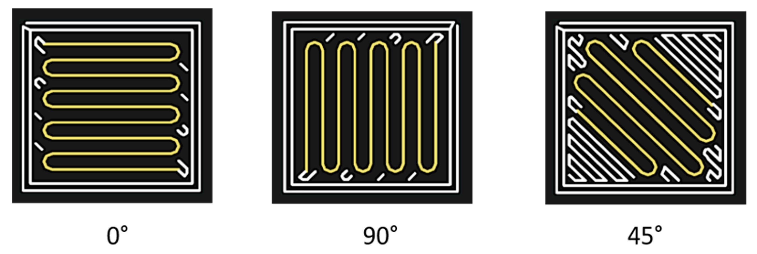
2.2. Specimen Fabrication
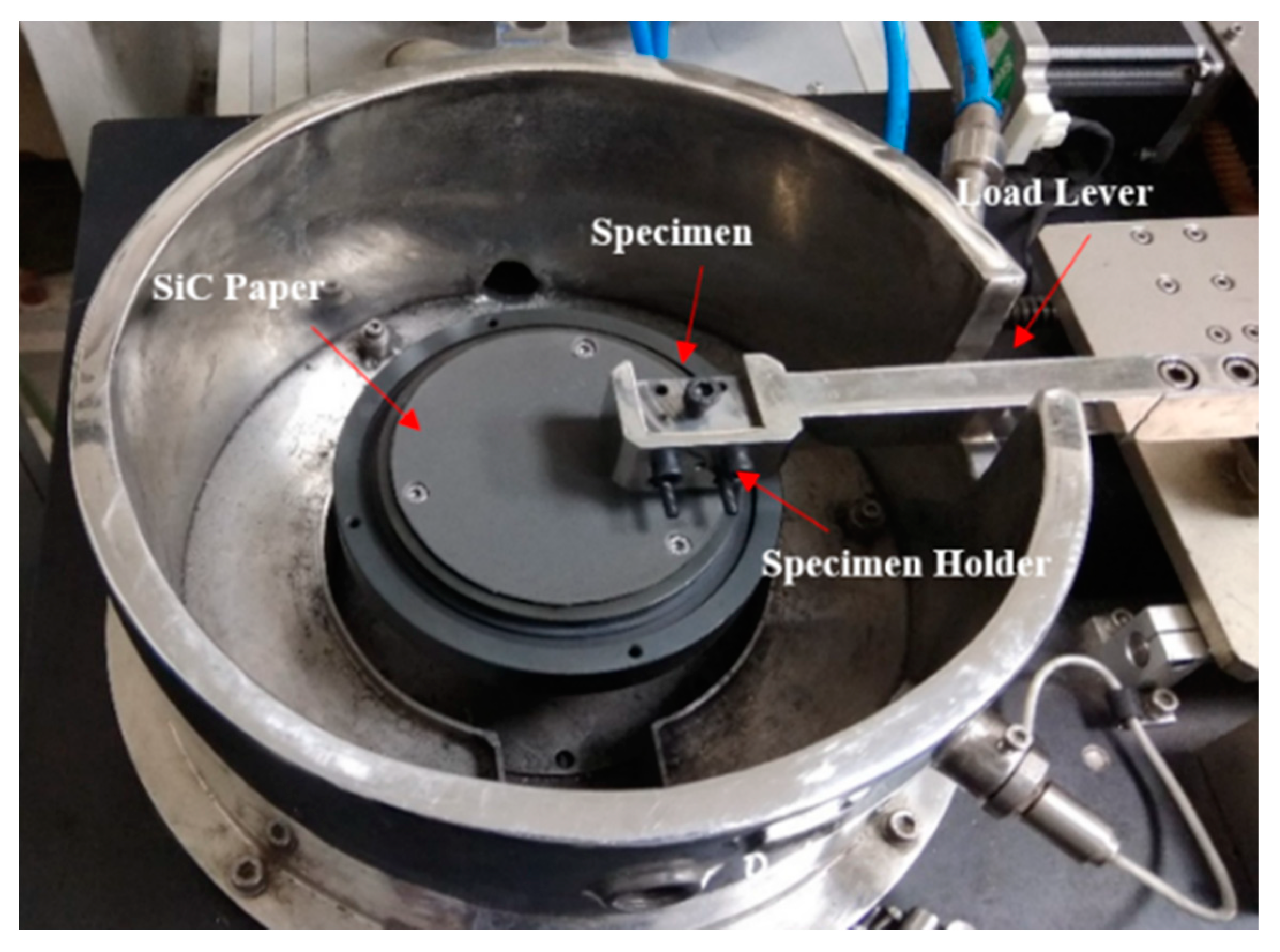
The specimens of dimensions 10 × 10 × 8 mm3 are additively manufactured with a continuous CFRP composite specimen. The specimen size and shape are considered as per the requirements of the specimen holder. The 3D model of the specimen is designed using the Solidworks modeling software and exported in STL format. It is then transferred to the Eiger software, where all of the printing parameters are assigned, and the slicing of the model is carried out as per the defined layer height. Further, the file is saved to an mfp file format using Eiger and transferred to the 3D printer. Based on the mfp file, the 3D printer starts depositing the material layer-by-layer on the print bed, and the part is fabricated.
All specimens were fabricated with a layer height of 0.125 mm, 100% infill density, two wall layers, and an isotropic fiber fill type. The wall layers were printed by onyx, and the infill was printed by the fibers. The isotropic fiber fill type helped to fabricate the specimen with different fiber orientations. In this study, the specimens were fabricated by considering three fiber orientations, i.e., 0°, 45°, and 90°, as shown in Figure 2 (the white line represents the wall layers of the onyx material, and the yellow line represents the fiber reinforcement with the defined orientation).

2.3. Wear Testing

Pin-on-disk wear test equipment (DUCOM WO-1883) was used to perform the wear test with a data acquisition system, as shown in Figure 3. The equipment is versatile and is designed to study wear under sliding conditions only. An investigation on the wear properties such as the COF and wear of the polymer composite is conducted against a disk with an abrasive surface under dry sliding conditions. Nagaraju et al. (2011) [16] reported that the wear is very low for polymer composites against a steel surface due to the formation of a thin protective film. The steel disk surface was converted to an abrasive by pasting on silicon carbide paper of 400 grit size. The test parameters were selected based on literature reviews under ASTM G99 [17], shown in Table 1. In this work, the fixed parameters were rotational speed, test duration, track diameter, and temperature, and the varying parameter was the applied load. Before each test, using SiC paper, the surface of all specimens was polished to ensure proper contact between the specimen and the abrasive surface of the disk. The specimens were then cleaned with acetone to remove the worn-out plastic debris before each test. The wear in micron and COF value were obtained from the Winducom 2010 software (2010, Ducom Instruments (Asia), Bangalore, India).

3. Results and Discussion

3.1. Abrasive Wear Properties

This section discusses the influence of load and fiber orientation on the abrasive wear properties of continuous CFRP composites. The specimens were slid against SiC abrasive paper with a varying load at a constant speed of 100 rpm. Figure 4 represents the results of the wear and COF for the varying load and fiber orientation of the composites. It is observed that the wear and COF significantly influence the varying load and fiber orientation of AM composites. The maximum wear value at the 10 N load for the 0° orientation is 37.32 microns, for the 45° orientation is 41.06 microns, and for the 90° orientation is 48.83 microns.
Similarly, considering the maximum load to 50 N, the wear for the 0° orientation is 88.92 microns, for the 45° orientation is 93.99 microns, and for the 90° orientation is 155.6 microns. It is observed from the result that the high load and increasing fiber angle have high wear because the percentage increase in the wear is 58.02% for the 0° orientation, 56.31% for the 45° orientation, and 68.61% for the 90° orientation. The minimum effect on wear and COF is observed for the 0° fiber orientation, and the maximum effect on the wear and COF is observed for the 90° fiber orientation. Similar results were observed in [12], whereby the wear of banana-reinforced composites increases with an increase in the load and fiber angle.

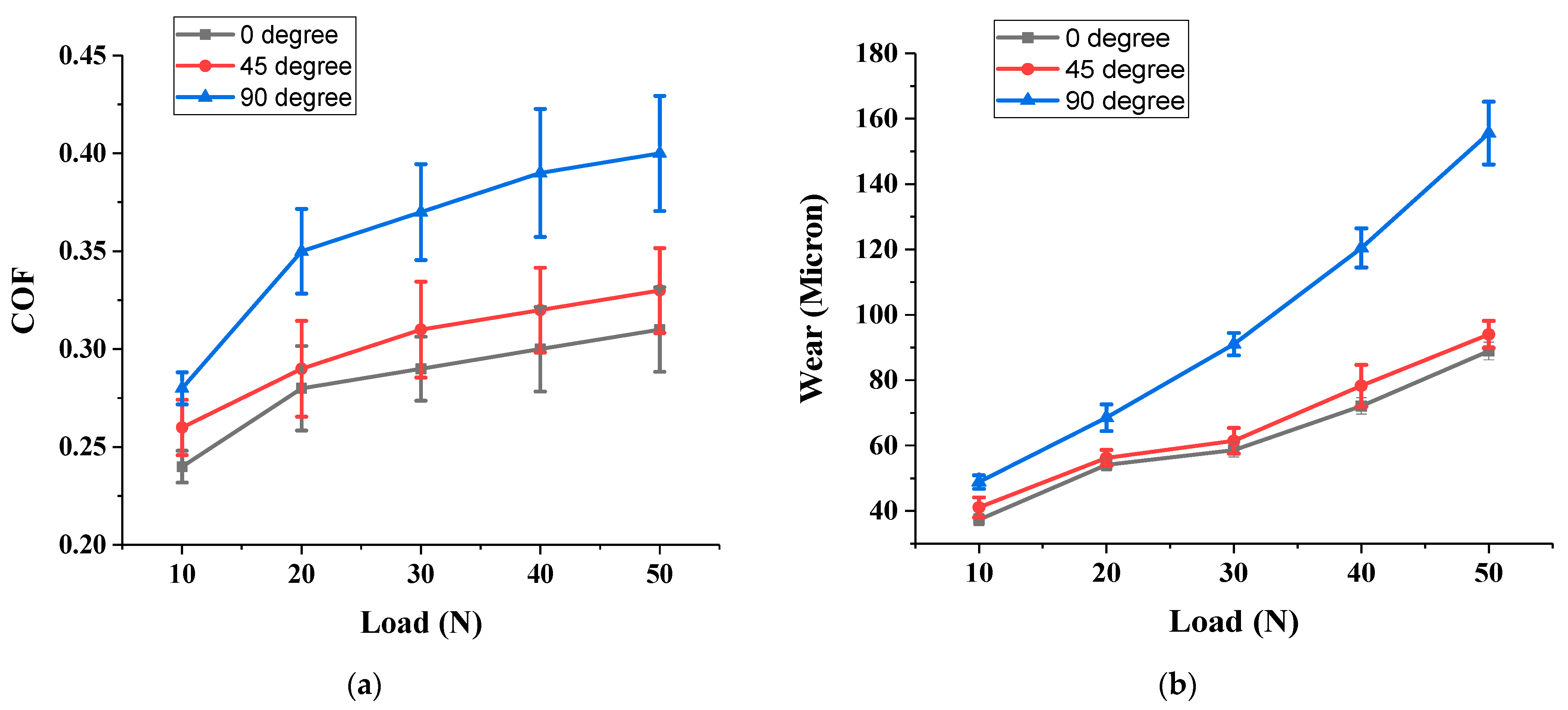
3.2. Effect of Applied Load

The wear and COF increase as the load increases, as shown in Figure 4. In abrasive wear, the fiber protects the matrix, which undergoes a substantial wear process by thinning when the fibers are orientated parallel to the sliding direction. If fibers are orientated perpendicular to the sliding direction, it results in maximum fiber cutting and minimum wear thinning, leading to very high wear, as shown in Figure 4a.
Figure 4b shows that the COF increases as the load increases. As the load increases, the interface temperature rises and softens the polymer material, which leads to adhesion, and hence COF increases [18]. In addition, the thin film formed at the interface is damaged due to the high contact pressure, resulting in an increasing COF. The friction is less at lower loads because the carbon fibers form a thin protective film due to the capability of solid lubrication. However, this advantage of carbon fiber fails at higher loads because, at higher loads, the protective film breaks as the pressure increases, leading to increased COF.

3.3. Effect of Fiber Orientation

As shown in Figure 4, the wear and COF increase as the fiber orientation angle increases. During sliding, the fibers carry the shear force acting on the specimen. If the fiber–matrix interface is good, this leads to better load transference by the fibers. The force generated is divided into two components: Fcos θ and Fsin θ. The direction of Fcos θ is parallel to the fiber orientation, and the direction of Fsin θ is perpendicular to the fiber orientation. Fcos θ is significant concerning fiber orientation. For the 0° fiber orientation, Fcos θ has a high magnitude, leading to most of the force being carried by the fibers. When the fibers carry the maximum force, low forces are transferred to matrix and interface, resulting in low specimen wear. For the fiber orientation angle at 90°, Fsin θ has a high magnitude, leading to the majority of the force being carried by the matrix and interface. When the matrix carries the maximum force, low forces are transferred to the fibers, resulting in more fibers peeling off the matrix, and the wear increases. As the fiber orientation increases, the COF increases, as shown in Figure 4b. As the fiber orientation increases, the wear increases by cracking and cutting the fibers, and these cut pieces of fiber oppose easy sliding, which results in higher COF. From Figure 4a,b, it is observed that the COF and wear vary non-linearly with increasing load because the layer-by-layer deposition of fibers leads to improper bonding and porosity, which may lead to the varying values of wear and COF at different loads.

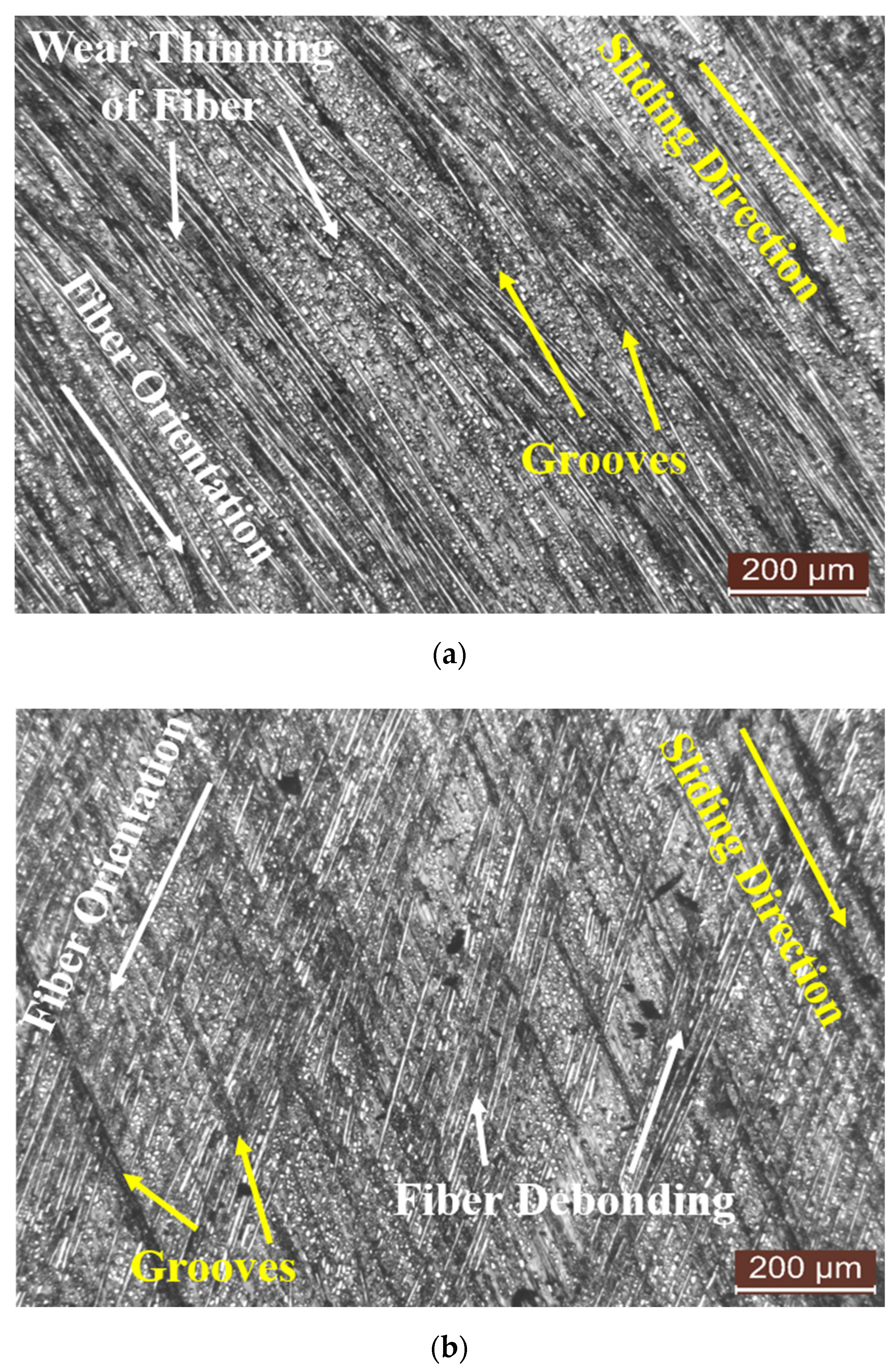
3.4. Optical Micrograph Studies

Studies on worn surfaces are carried out using optical microscope images to understand the wear mechanism. Figure 5 represents the optical images of the worn surface of AM composites. The optical images represent the effect of fiber orientation, resulting in fibers debonding from the matrix, fiber cracking and cutting pulverization, and the removal of fibers from the matrix in the form of debris, which leads to a change in the COF. The increase in the fiber angle, i.e., 0°, 45°, and 90°, enhances the matrix and fiber damage and is correlated to wear behavior. It is also observed that as the fiber orientation increases, the wear thinning of the fiber decreases, and fiber fracture increases with the random dispersion of fiber debris. From Figure 5, for the 0° fiber orientation, mostly minor damage to the fibers and fiber–matrix interface is observed. The least peeling off of fibers is observed with maximum wear thinning, and the fibers are also well covered with a matrix, which results in minimum wear. For the 45° fiber orientation, the debonding of fibers and peeling off from the matrix are observed. The wear thinning of the fibers is lower, and debonding is increased in comparison to the 0° fiber orientation. For the 90° fiber orientation, the maximum fracture of fibers is observed due to cracking and cutting, which has led to high wear.

4. Conclusions

The present research examined the wear properties of additively manufactured composite fabricated using the FDM process. The influence of applied load and fiber orientation on wear properties were investigated using pin-on-disk equipment at a run time of 600 s and a constant speed of 100 rpm. The wear and COF were significantly affected by the applied load and fiber orientation. The following conclusions were observed from the experimental wear study:
  • The wear and COF increase as the load and fiber orientation angle increases.
  • For the 0° fiber orientation, the minimum effect on wear and COF was observed; for the 90° fiber orientation, the maximum effect on wear and COF was observed.
  • The morphological study of worn-out surfaces of AM polymer composites represents various reasons for the fiber fracture and matrix failure at different fiber orientations.
  • For the 0° fiber orientation, the maximum wear thinning of the fibers occurs, which results in minimum wear; for the 45° fiber orientation, some debonding of fibers from the matrix is observed with wear thinning of the fibers, and for the 90° fiber orientation, the maximum fiber fracture results in maximum wear.
Additional research can be conducted to investigate the effect of additional variables on the wear properties of AM polymer composites.

Author Contributions

Conceptualization, M.N. and D.G.T.; methodology, M.N. and S.S.; software, M.N. and S.C.; validation, M.N. and S.C.; formal analysis, M.N. and D.G.T.; investigation, M.N. and D.G.T.; resources, M.N., S.S. and H.M.A.H.; data curation, M.N., S.C. and S.S.; writing—original draft preparation, M.N., D.G.T., S.S. and H.M.A.H.; writing—review&editing, M.N., D.G.T., S.S. and H.M.A.H.; visualization, M.N., S.C., S.S. and H.M.A.H.; supervision, M.N. and D.G.T.; project administration, M.N., D.G.T. and S.S. All authors have read and agreed to the published version of the manuscript.

Funding

This research received no external funding.

Data Availability Statement

The data is contained within the manuscript.

Conflicts of Interest

The authors declare no conflict of interest.

References

  1. Bijwe, J.; Nidhi. Potential of fibers and solid lubricants to enhance the tribo-utility of PEEK in adverse operating conditions. Ind. Lubr. Tribol. 2007, 59, 156–165. [Google Scholar] [CrossRef]
  2. Naik, M.; Thakur, D. Experimental investigation of effect of printing parameters on impact strength of the bio-inspired 3D printed specimen. Sadhana 2021, 46, 151. [Google Scholar] [CrossRef]
  3. Kim, S.S.; Shin, M.W.; Jang, H. Tribological properties of short glass fiber reinforced polyamide 12 sliding on medium carbon steel. Wear 2012, 274–275, 34–42. [Google Scholar]
  4. Unal, H.; Findik, F. Friction and wear behaviors of some industrial polyamides against different polymer counterparts under dry conditions. Ind. Lubr. Tribol. 2008, 60, 195–200. [Google Scholar] [CrossRef]
  5. Aigbodion, V.S.; Hassan, S.B.; Agunsoye, J.O. Effect of bagasse ash reinforcement on dry sliding wear behavior of polymer matrix composites. Mater. Des. 2012, 33, 322–327. [Google Scholar] [CrossRef]
  6. Naik, M.; Thakur, D.; Chandel, S.; Salunkhe, S. Experimental investigations on thermal, flame retardant, and impact properties of additively manufactured continuous FRPC. Polym. Compos. 2022, 43, 2941–2951. [Google Scholar] [CrossRef]
  7. Jongsomji, B.; Panpranot, J.; Praserthdam, P. Effect of nanoscale SiO2 and ZrO2 as the filler on the microstructure of LLDPE nano-composite synthesized via in situ polymerization with zirconocene. Mater. Lett. 2007, 61, 1376–1409. [Google Scholar] [CrossRef]
  8. Zhao, G.; Hussainova, I.; Antonov, M.; Wang, Q.; Wang, T.; Yung, D.-L. Effect of temperature on sliding and erosive wear of fiber-reinforced polyimide hybrids. Tribol. Int. 2015, 82, 525–533. [Google Scholar] [CrossRef]
  9. Xu, L.; Zhu, Z.; Chen, G.; Qu, C. Effect of load and sliding velocity on tribological behaviors of aramid fiber reinforced PA1010 composites. Ind. Lubr. Tribol. 2010, 62, 46–51. [Google Scholar] [CrossRef]
  10. Sharma, M.; Rao, I.M.; Bijwe, J. Influence of orientation of long fibers in carbon fiber–polyetherimide composites on mechanical and tribological properties. Wear 2009, 267, 839–845. [Google Scholar] [CrossRef]
  11. Stanley, W.F.; Bandaru, A.K.; Rana, S.; Parveen, S.; Pichandi, S. Mechanical, dynamic-mechanical and wear performance of novel non-crimp glass fabric-reinforced liquid thermoplastic composites filled with cellulose microcrystals. Mater. Des. 2021, 212, 110276. [Google Scholar] [CrossRef]
  12. Chavali, P.J.; Taru, G.B. Effect of Fiber Orientation on Mechanical and Tribological Properties of Banana-Reinforced Composites. J. Fail. Anal. Prev. 2021, 21, 1–8. [Google Scholar] [CrossRef]
  13. Lasikun; Ariawan, D.; Surojo, E.; Triyono, J. Effect of fiber orientation on tensile and impact properties of Zalacca Midrib fiberHDPE composites by compression molding. AIP Conf. Proc. 2018, 1931, 030060. [Google Scholar]
  14. Vigneshkumar, S.; Rajasekaran, T. Experimental analysis on tribological behavior of fiber reinforced composites. In Proceedings of the IOP Conference Series: Materials Science and Engineering 2018, Kattankulathur, India, 22–24 March 2018; Volume 402, p. 012198. [Google Scholar]
  15. Kichloo, A.F.; Raina, A.; Haq, M.I.U.; Wani, M.S. Impact of Carbon Fiber Reinforcement on Mechanical and Tribological Behavior of 3D-Printed Polyethylene Terephthalate Glycol Polymer Composites—An Experimental Investigation. J. Mater. Eng. Perform. 2022, 31, 1021–1038. [Google Scholar] [CrossRef]
  16. Nagaraju, B.; Ramji, K.; Prashad, V.S.R.K. Studies on tribology properties of ZnO filled polymer nanocomposites. ARPN J. Eng. Appl. Sci. 2011, 6, 75–82. [Google Scholar]
  17. ASTM G99; Standard Test Method for Wear Testing with a Pin-on-Disk Apparatus. ASTM International: West Conshohocken, PA, USA, 2017.
  18. Ludema, K.C.; Tabor, D. The Friction and Visco-Elastic Properties of Polymeric Solids. Wear 1966, 9, 329–348. [Google Scholar] [CrossRef]
Figure 1. Mark Two 3D printer.
Crystals 12 01481 g001
Figure 2. Orientation of reinforced continuous carbon fiber in wear specimen.
Crystals 12 01481 g002
Figure 3. Pin-on-disk wear test equipment.
Crystals 12 01481 g003
Figure 4. (a) Wear vs. load for different fiber orientations; (b) COF vs. load for different fiber orientations.
Crystals 12 01481 g004
Figure 5. Optical micrograph of wear surfaces at 50 N load with different fiber orientation angles: (a) 0°, (b) 45°, and (c) 90°.
Crystals 12 01481 g005aCrystals 12 01481 g005b
Table 1. Testing parameters for tribology test.
ParametersValue
Sliding speed (rpm)100
Test duration (sec)600
Track diameter (mm)50
Applied load (N)10, 20, 30, 40, 50
Temperature (°C)27
EnvironmentAir
Publisher’s Note: MDPI stays neutral with regard to jurisdictional claims in published maps and institutional affiliations.

