Article

In Situ Synchrotron Radiation Diffraction Study of Compression of AZ91 Composites Reinforced with Recycled Carbon Fibres

1
Institute of Metallic Biomaterials, Helmholtz-Zentrum Hereon, Max-Planck Str. 1, D-21502 Geesthacht, Germany
2
Department of Materials Science & Metallurgy, University of Cambridge, 27 Charles Babbage Road, Cambridge CB3 0FS, UK
3
Institute of Material and Process Design, Helmholtz-Zentrum Hereon, Max-Planck Str. 1, D-21502 Geesthacht, Germany
4
Institute of Materials Physics, Helmholtz-Zentrum Hereon, Max-Planck Str. 1, D-21502 Geesthacht, Germany
5
Department of Mechanical Engineering, Federal University of São Carlos, Rod. Washington Luis km 235, São Carlos 13565-905, Brazil
*
Author to whom correspondence should be addressed.
Crystals 2022, 12(11), 1502; https://doi.org/10.3390/cryst12111502
Submission received: 27 September 2022 / Revised: 18 October 2022 / Accepted: 19 October 2022 / Published: 22 October 2022

Abstract

:
Lightweight structural materials are increasingly sought after in the automotive and aerospace industries for their potential to improve fuel efficiency. Magnesium-based metal-matrix composites are potential candidates for these kinds of applications. The use of recycled carbon fibres offers further energy and cost savings. The recycled carbon fibre composites were manufactured by stir casting with high-dispersion shearing, then were extruded and subsequently heat treated. The compressive deformation mechanisms of the composites compared to AZ91 were investigated using in situ synchrotron radiation diffraction. An increase in ultimate compressive strength was achieved in the composites compared to AZ91. The deformation mechanisms active in the composites were similar to those in AZ91. Magnesium alloys in compression typically show extensive twinning; this was observed in AZ91 and the AZ91 composites. The stress required for twinning onset was increased in the composites, and the twin volume fraction at failure was decreased compared to AZ91.

1. Introduction

Sustainability has become an important consideration for manufacturers in recent years. One method of improving sustainability in the automotive and aerospace industries is improving fuel efficiency by using lightweight materials. Magnesium is a promising candidate for these applications—it is lightweight, has a high strength-to-weight ratio, and good machinability and castability. Alloying additions can further improve these properties as well as improving corrosion resistance and ductility. However, Mg alloys generally suffer from poor creep resistance, making them unsuitable for high-temperature applications. Common alloying additions used for room-temperature applications are aluminium–manganese (AM50 and AM60 commercial alloys) and aluminium–zinc (AZ31 and AZ91 commercial alloys). Currently, metal-matrix composites (MMCs) using a Mg alloy matrix are a subject of interest. They may offer improved mechanical properties, whilst retaining Mg alloys’ light mass [1]. As well as structural applications, Mg alloys are also favoured for medical applications as a biodegradable implant material [2,3,4].
Previous work on Mg composites includes additions of ceramic particles or fibres [5,6,7], carbon nanotubes [8,9,10], and carbon fibres (CFs). The interface between the matrix and the reinforcement phase in composites is crucial for maintaining strength, toughness, and fatigue resistance. Various authors have investigated the CF-Mg alloy interface of coated and uncoated CFs [11,12]. Different manufacturing techniques have also been trialled: squeeze casting [11,13,14], gas pressure infiltration [15,16], friction stir processing [17], stir casting [18], and stir casting using shearing [19]. It is generally accepted that reducing the formation of brittle aluminium carbide precipitates at the interface improves mechanical properties. However, some surface reactivity is desirable for a strong bond between matrix and fibre for load transfer [1], which can be promoted by the addition of Al as an alloying addition [20].
Sustainability can also be considered when choosing a reinforcing addition. Kandemir et al. [19] investigated cast AZ91 composites reinforced with recycled carbon fibres (rCFs). Recovered from carbon-fibre-reinforced polymers (CFRPs), these maintain many of the mechanical properties of virgin CFs, but are cheaper and less energy intensive to produce [21]. Finding uses for rCFs will also encourage more commercial recycling of carbon fibre reinforced composite materials [22,23].
The compressive deformation mechanisms of extruded composites using the same rCF-reinforced AZ91 cast material as Kandemir et al. [19] were studied. The composites were heat treated, then deformation processes were investigated using in situ synchrotron radiation diffraction. This technique can extract detailed information on the active deformation mechanisms as a sample is deformed. It has excellent time resolution, allowing deformation to be measured before relaxation occurs [24]. Lattice strain can be evaluated by considering shifts in diffraction peaks and using Bragg’s law. Twinning can be observed by simultaneous intensity changes of reflections from the lattice planes of the parent and daughter crystallites [24]. In situ neutron diffraction experiments use the same principles as synchrotron diffraction, being able to achieve better sampling statistics at the expense of time resolution. Neutron diffraction has been used extensively to study deformation in Mg [25,26]. Synchrotron radiation diffraction has been used to study deformation in Mg alloys with special attention to the effect of precipitates [27,28]. Garcés et al. [5,6,7] undertook a series of in situ studies using AZ31 and SiC as a reinforcement. Meixner et al. [29] also investigated an Mg composite with ceramic reinforcements. To the authors’ knowledge, this work is the first investigating the deformation mechanisms of a CF-reinforced Mg alloy using an X-ray diffraction technique. The aim of this study was to understand how the heat treatments and CF reinforcement affect twinning and slip in composite materials. These insights may then be used to develop high-performance composites.

2. Materials and Methods

2.1. Sample Preparation

Three samples were prepared, AZ91, AZ91 with 5 wt % rCFs with a 100 µm average length (denoted AZ91/C100/5f), and AZ91 with 5 wt % rCFs of 500 µm average length (denoted AZ91/C500/5f). The rCFs had an average diameter of 6 µm. Further details can be found at https://www.carbonxt.de/en/products/ (accessed 1 August 2022). The rCFs were first baked at 400 °C to remove any polymer remnants and adsorbed gasses, then placed in aluminium foil bags to be added into the melt. A commercial AZ91 alloy was heated to 719 °C under a protective atmosphere of Ar with 1% SF6. The composition of the alloy was measured using spark spectrometry (Spectrolab M9, Ametek-Spectro, Kleve, Germany) and is given in Table 1. Each type of rCF was added to a melt, which was sheared at 2000 rpm by a shearing device (Zyomax Ltd., Uxbridge, UK) for five minutes. Previous work has shown this to be effective at dispersing particles and fibres in a melt [19,30,31].
The melts were then cast in cylindrical steel moulds preheated to 500 °C with a diameter of 100 mm and 200 mm height. Each mould contained 3 kg of alloy at 670 °C. These were lowered into a room-temperature water bath at 100 mm/min, ensuring controlled solidification.
The three different materials (AZ91, AZ91/C100/5f, AZ91/C500/5f) were machined to produce billets 150 mm long and 50 mm in diameter. These were preheated to 300 °C for an hour, then extruded indirectly to form bars of 10 mm in diameter using a 2.5 MN extrusion press (Müller Engineering GmbH and Co. KG, Berlin, Germany). The extrusion ratio was 1:25 with a ram speed of 1.4 mm/s. For each of the unreinforced, C100, and C500 extruded bars, three samples were produced. One set had no further heat treatment; one set was annealed at 413 °C for 20 h (T4); and one set, following T4, was aged at 170 °C for 16 h (T6).

2.2. Microstructural Investigation

The samples were prepared for microstructural investigation via mechanical polishing using SiC paper and a final polishing using OPS water-free solution and 0.25 µm diamond suspension solution.
The microstructure was first investigated using an optical microscope, Olympus BX53 (Olympus Europa SE and Co. KG, Hamburg, Germany). Average grain sizes for each sample were obtained by etching the material using AC2 Struers solution. The microstructure was then imaged via polarised light in order to clearly see the grains. A line intercept method was used on an average of 100 grains to determine the average grain size. This was performed three times per sample, and the average result was recorded.
The microstructure of these samples was further investigated using a Tescan Vega scanning electron microscope (SEM) (Tescan, Brno, Czech Republic) set at 15 kV and 15 mm working distance. The micrographs were recorded using backscattered electrons (BSE), and energy-dispersive X-ray spectroscopy (EDX) was used for compositional analyses.

2.3. Synchrotron Diffraction Measurements

For the in situ compression experiments, cylindrical specimens were machined from the extruded bars longitudinally with a diameter of 5 mm and length of 10 mm. The in situ synchrotron radiation diffraction was performed at the P07 beamline of PETRA III, DESY (Deutsches Elektronen-Synchrotron). A monochromatic beam with the energy of 100 keV (λ = 0.0124 nm) and with a cross section of 1 × 1 mm2 was used. Diffraction patterns were recorded with a PerkinElmer 1622 flat panel detector with a pixel size of (200 µm)2, which was placed at a sample-to-detector distance of 1555 mm from the specimen (calibrated with a LaB6 standard powder sample). The acquisition time for each image was 0.1 s. The specimens were placed in the chamber of a dilatometer DIL 805A/D (TA Instruments, New Castle, DE, USA). The specimens were compressed at room temperature with an initial strain rate of 1.0 × 10⁻³ s−1. The tests were terminated at fracture.
The morphology of the Debye–Scherrer rings was then analysed using the Fit2D® software. A Gaussian peak-fitting script was written in Python and used to extract peak position and to calculate the intensity from the area under each peak.
The strain on each lattice plane was calculated using Bragg’s law:
d = h c 2 sin θ E ,
The strain on a given lattice plane is [32]
ε i = d i d 0 d 0 = sin θ 0 sin θ i 1   .
The initial θ 0 value was the value measured at the start of the deformation experiment, and thus all strains observed were relative to the initial strains within the sample.
The intensity of the {10.0} and {00.2} peaks was measured in arbitrary units corresponding to the area under each peak. The simultaneous increase in {00.2} intensity and decrease in {10.0} intensity was a result of extension {10.2} 10.1 twinning as the lattice was reoriented by 86°. This resulted in an increase in {00.2} planes that fulfil the diffraction conditions [26].

3. Results

3.1. Deformation Behaviour

The deformation curves of the nine samples are shown in Figure 1. The highest ultimate compressive strength (UCS) was the as-extruded AZ91/C500/5f sample. The ductility of each T4 (annealed) sample was improved in comparison to the as-extruded and T6 samples of the same composition. The proof stress, stress for 0.2% deformation, and the UCS of each sample are presented in Table 2. An increase of 41 MPa in UCS was seen between the as-extruded AZ91 and AZ91/C500/5f samples, and an increase of 32 MPa between AZ91 and AZ91/C100/5f.
The shape of deformation curves can also provide information about the deformation mechanism; a sigmoidal shaped curve is indicative of deformation via twinning. This is investigated using diffraction data.

3.2. Microstructure

Figure 2 shows BSE micrographs of the samples; the extrusion direction is horizontal. After extrusion, optical and SEM microscopy on all samples showed elongated Al-rich precipitates, labelled 2, and small spherical Mn-rich precipitates, labelled 3, 4, and 5 in an Mg-based matrix, labelled 1. The samples containing CFs showed a fairly even distribution of CFs, mostly orientated with their long axis along the extrusion direction. Microscopy shows that the fibres measured less than their original lengths after sample preparation; this could have been due to breakage during extrusion or shearing [19]. There was also the formation of an Al-rich region at the fibre-matrix interface, labelled 7. The compositions of the labelled regions from EDX are provided in Table 3.
The average grain sizes are provided in Table 4. T4 heat treatment led to significant grain growth, whereas there was no further significant grain growth after T6 heat treatment. The composite samples showed some grain refinement. After T4 heat treatment, significantly fewer precipitates were observed in the matrix, indicating that it was predominantly a solid solution, although an interfacial layer remained visible. Growth of the Mn-rich precipitates can also be observed.
After T6 heat treatment, the Al-rich layer at the matrix–fibre interface remained in the C100 and C500 samples. There was some growth of precipitates, which is the desired result of the ageing process. In the unreinforced AZ91 sample, dark spots were visible on the SEM image, with these being artefacts of sample preparation.

3.3. Synchrotron Diffraction

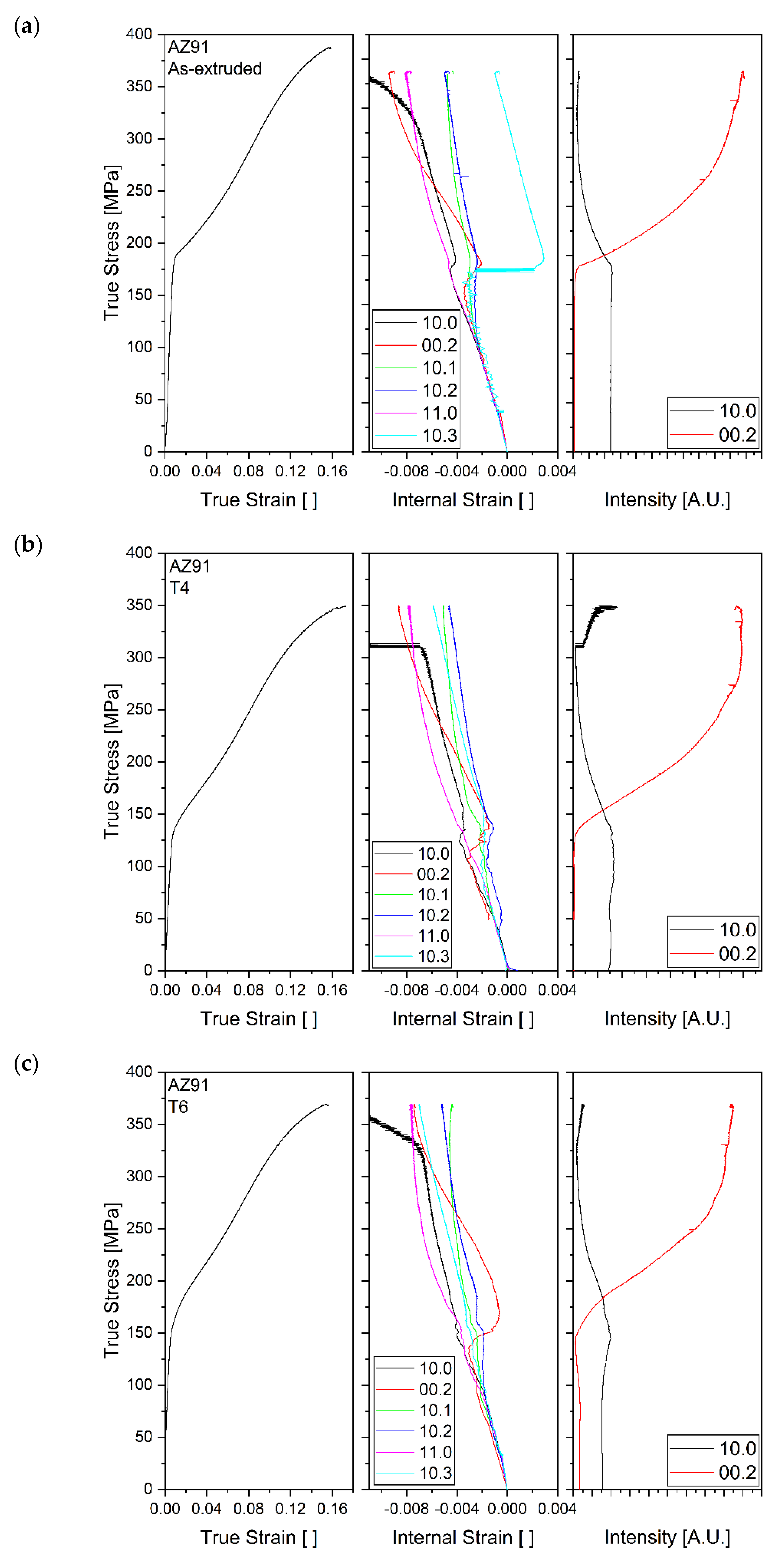
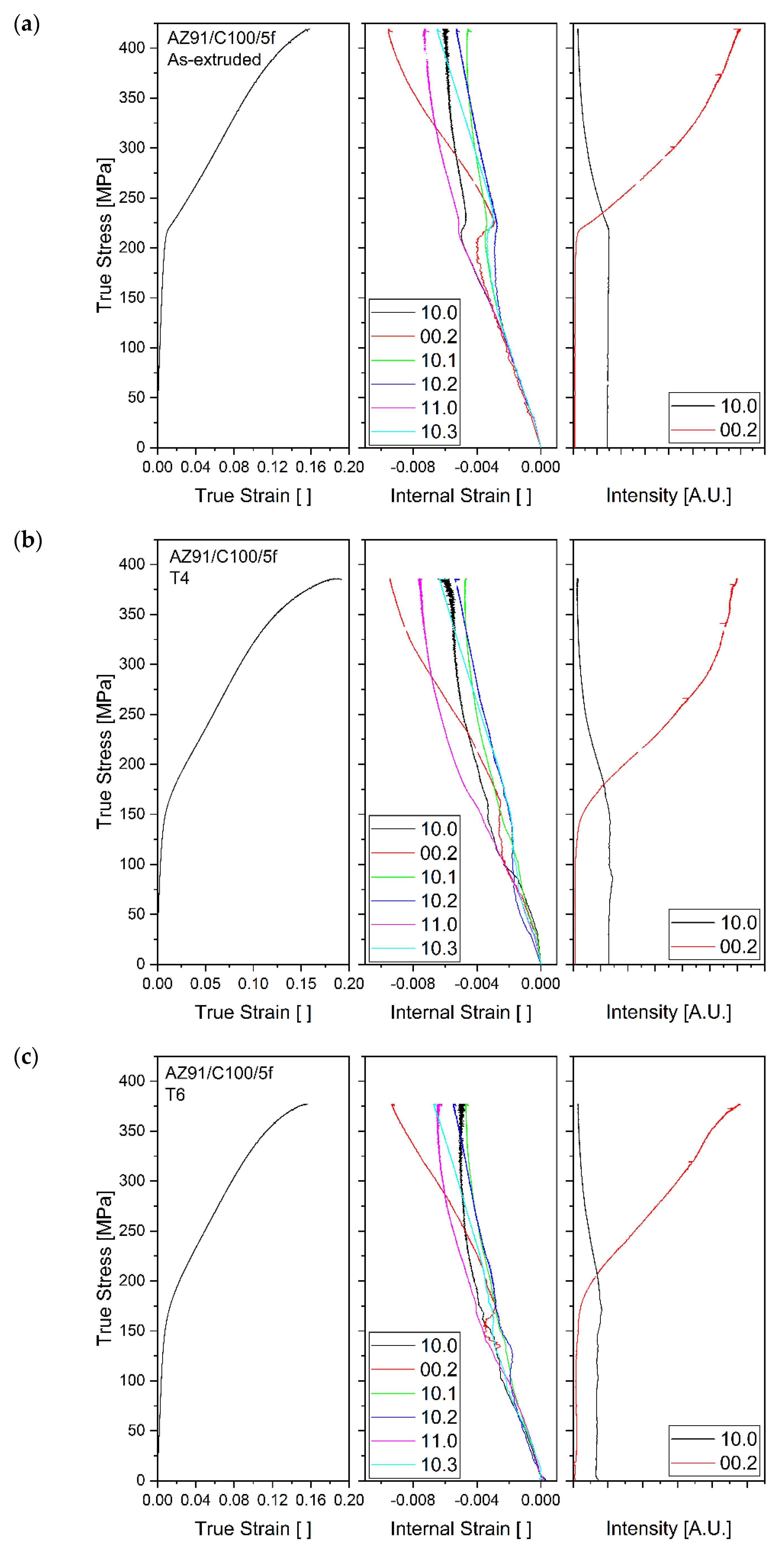
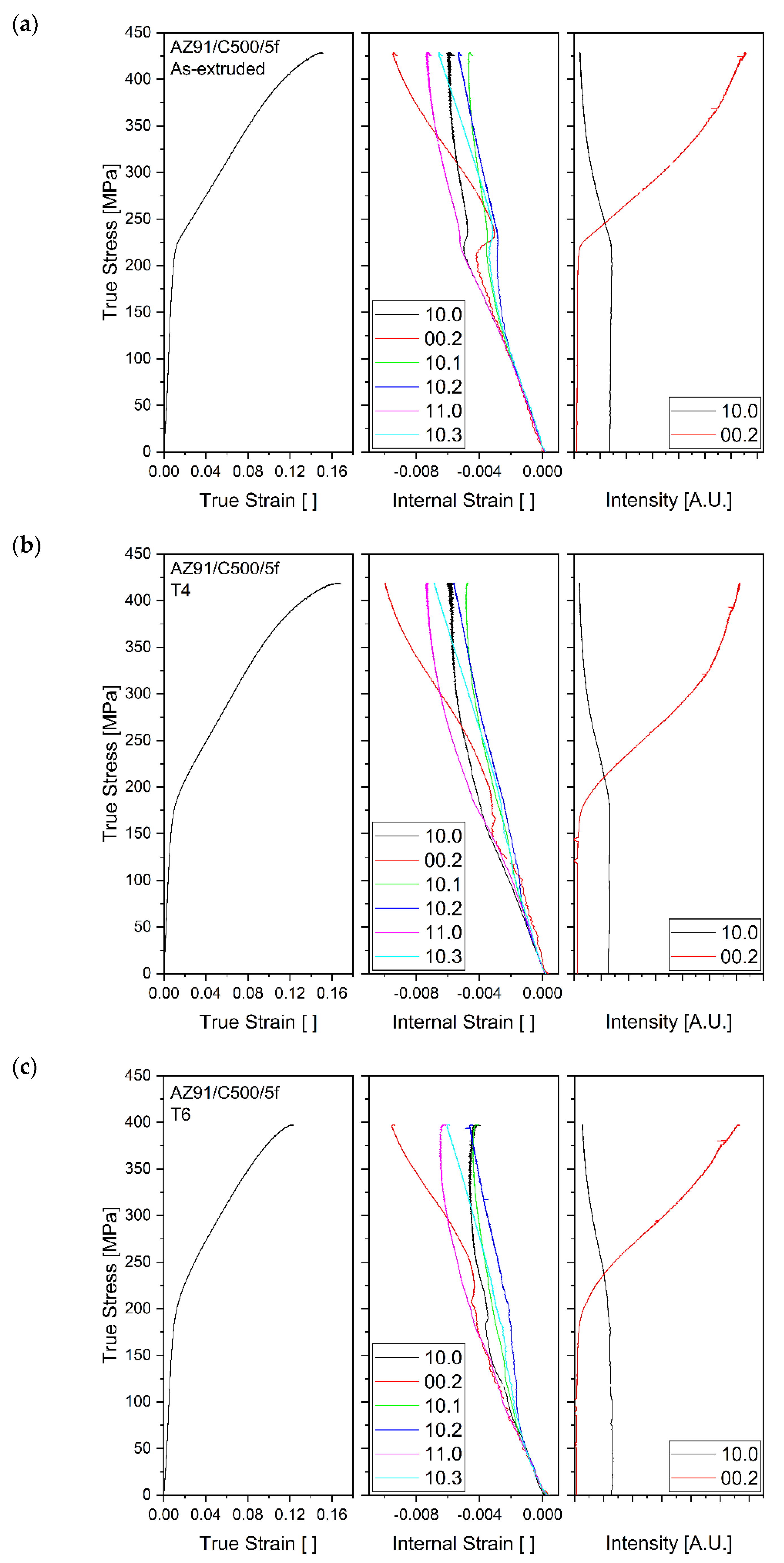
The results from the in situ synchrotron radiation diffraction tests during compression are shown in Figure 3, Figure 4 and Figure 5 of AZ91, AZ91/C100/5f, and AZ91/C500/5f, respectively. They each show three plots for the as-extruded, T4, and T6 samples. Each plot had three sub-plots with a common true stress axis, from left to right: the macroscopic deformation curve, the strain on individual lattice planes, and the intensity of the {10.0} and {00.2} planes. The axial diffraction results are shown; previous work has shown the information gathered from radial and axial detection is identical, so all results presented here are axial measurements [7].
General features of the graphs are an initial linear elastic region demonstrating Mg’s elastic isotropy [1,29]. Below the stress required for macroscopic yielding, the onset of microyielding of the pyramidal {10.1}, {10.2}, and {10.3} planes was observed as a reduction in strain on these planes. A shallower gradient of the {10.0} and {11.0} was also seen after microyielding. In the as-extruded samples, this occurred at a stress of approximately 120 MPa, and in the heat-treated samples, it occurred between 70 and 90 MPa. At macroscopic yielding, a sudden increase in {00.2} and decrease in {10.0} intensity was seen. This coincided with a reduction in strain of the {00.2} planes.
Figure 6 is a comparison of the normalised intensity of {00.2} planes of the as-extruded samples. It shows the stress at the sharp increase in {00.2} intensity, indicative of the onset of twinning, was increased in the composites compared to AZ91. Figure 7 shows the effect of heat treatments on the stress for the onset of twinning by comparing the normalised {00.2} plane intensity of the AZ91 samples.
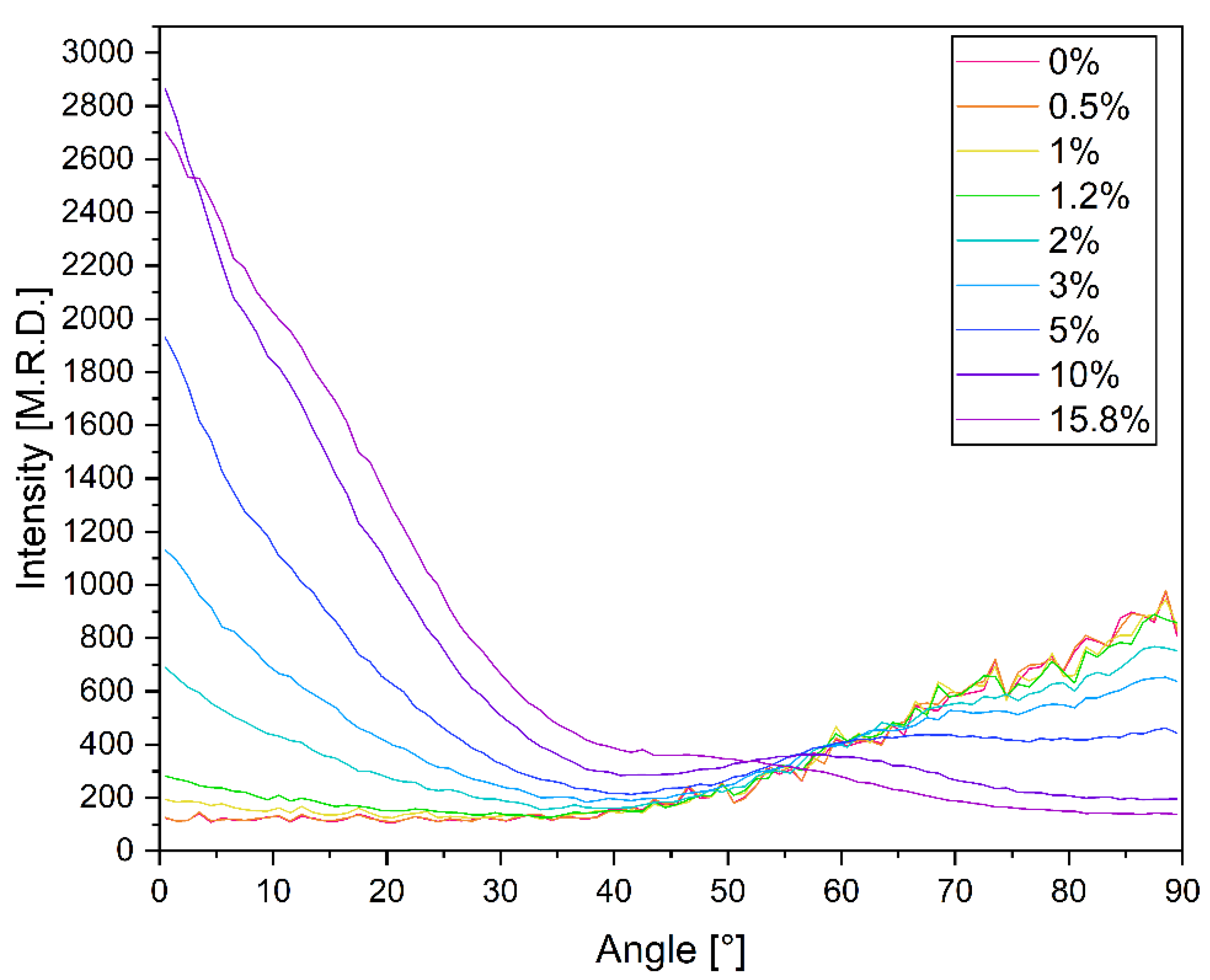
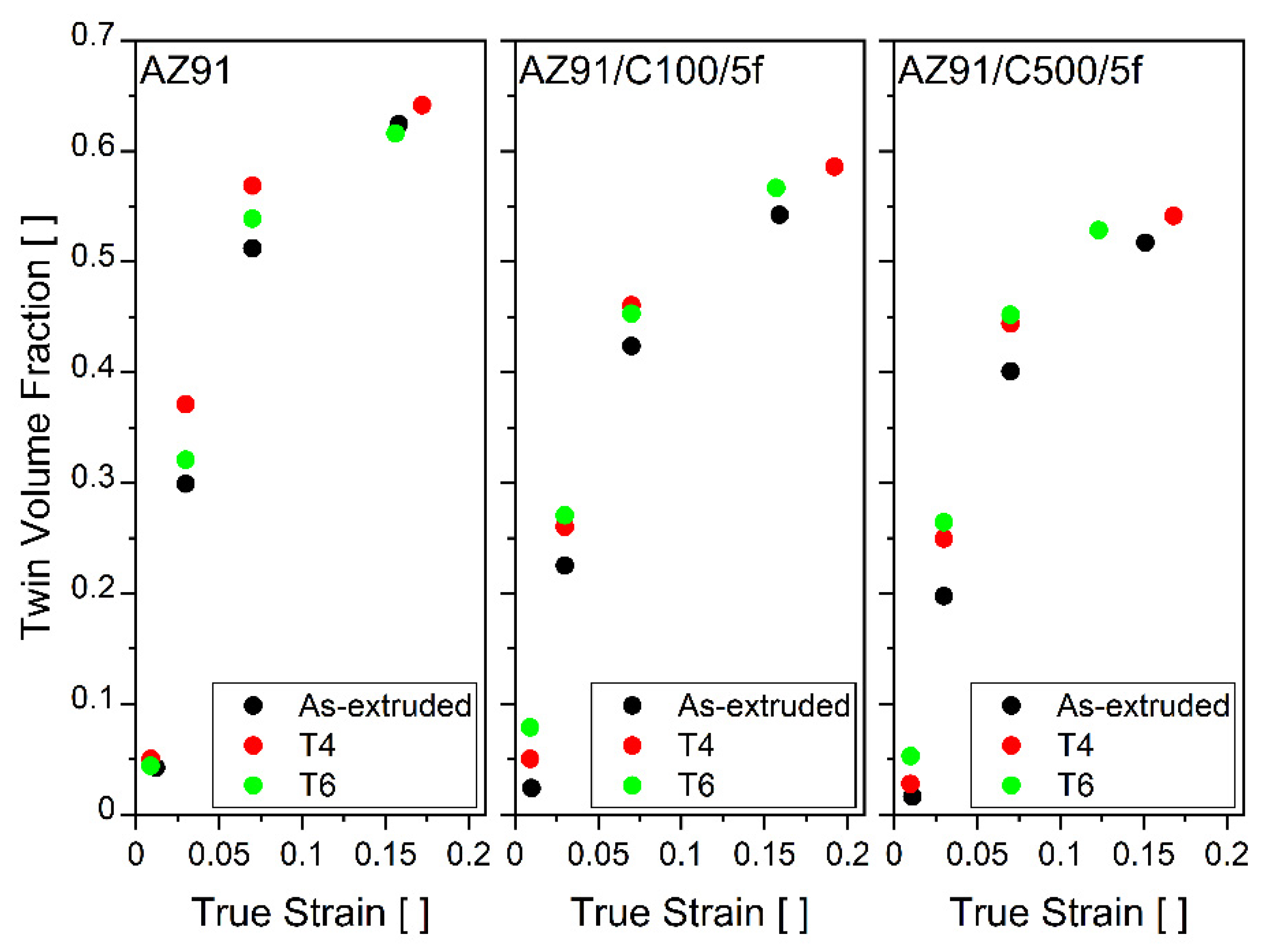
The twin volume fraction (TVF) of the matrix of each sample at various strains was calculated using the normalised azimuthal intensity distribution of the {00.2} planes. The TVF is the area between the initial intensity distribution and the distribution at failure, before a texture specific crossover point, 54.5°, for the samples used [33]. Figure 8 shows the evolution of the azimuthal intensity distribution function of as-extruded AZ91. It is reflective of the general change in intensity distribution of the {00.2} peaks with compression. The TVF fractions at failure are provided in Table 5, and the evolution of the TVF with strain is shown in Figure 9. TVFs of 0.5–0.7 are commonly reported for Mg alloys [33,34,35,36].

4. Discussion

AZ91 alloys are typically found to contain the intermetallic β-Mg17Al12 which can precipitate continuously or discontinuously [27,33,37]. Precipitation of various aluminium carbides at the fibre–matrix interface of uncoated and AZ91 has also been observed [20]. SEM and EDX analysis of our own samples showed β-Mg17Al12 precipitates distributed throughout the Mg matrix for the as-extruded samples and some growth of them for the T6 samples; further investigation would be required to determine the precipitation mechanisms. EDX did not detect significant quantities of carbon at the interface, excluding the presence of large quantities of carbides. Kandemir et al. [19] note the formation of the Al-rich region at the fibre–matrix interface, suggesting that Al may accumulate at the solidification front due to temperature differences between the melt and fibres during manufacturing. This is supported by the results shown in Table 3, where the interfacial layer, labelled 7, was shown to be majority Al. Brittle Mn-rich intermetallics are also seen in the sample, as shown in Figure 2e, where the precipitate was cracked.
The T4 heat treatment was designed to dissolve the secondary phases to reach a solid solution. The temperature required for this can also lead to some recrystallisation and grain growth (Table 4). The T4 heat-treated samples displayed the best ductility; the reduction in brittle [38] β-Mg17Al12 precipitates and an increase in grain size allow for easier dislocation motion, and thus an increase in plastic deformation before failure. Stanford et al. [39] also found solution-treated AZ91 to be the most ductile in their study of rolled and aged AZ91. However, these same factors lower the UCS of unreinforced T4 AZ91. Successful age-strengthening of AZ91 has been achieved in various studies [27,28,33,40]. Authors have attributed this to a combination of an increase the CRSS of basal slip and extension twinning, inhibition of twin growth, and load sharing between the matrix and precipitates [6,28,39,41]. There remains some uncertainty in terms of the details of these strengthening mechanisms and their relative importance. The T6 heat treatment used was not effective in strengthening the samples compared to their as-extruded condition, suggesting that the applied heat treatment conditions resulted in under-aged samples.
Figure 2 shows that the fibres break during manufacturing, either during shearing or extrusion. Further work is required to determine the cause of breakage and the lengths of the fibres in the extruded products. In Figure 2, the AZ91/C100/5f and AZ91/C500/5f appear to have fragments of a similar range of lengths, and the distribution of lengths cannot be determined from the micrographs alone. The similarity in fibre fragments explains observations of similar properties in the two reinforced samples.
Understanding the active deformation mechanisms during the compression of Mg alloys and composites can inform and enhance the design of future materials. The two deformation mechanisms with the lowest CRSS at room temperature were basal slip and extension twinning. Both of these mechanisms were seen to be active in the diffraction data. Figure 3, Figure 4 and Figure 5 show that basal slip occurred on the {00.2}, {10.1}, {10.2}, and {10.3} planes at well below the proof stress in all samples. This phenomenon is commonly observed in diffraction investigation of compression of Mg alloys [6,27,28,32,40,41,42,43]. The shallower gradient of the prismatic {10.0} and {11.0}, planes seen after the onset of microyielding shows that these planes bore increased strain as they were poorly oriented for basal slip. After yielding, at high stresses, non-linear behaviour was seen on the {10.0}, {00.2}, and {10.1} planes. This was a result of the activation of non-basal slip. Pyramidal slip including <c+a> slip occurred after the exhaustion of extension twinning; this was the only deformation mechanism that could accommodate strain on the c-axis.
The basal texture of the extruded alloys and composites means that there were very few grains oriented without their c-axes perpendicular to the compression direction and were thus able to slip on {10.1} and {10.2} planes. Although plastic deformation occurs below the proof stress, it does not cause macroscopic yielding. Figure 3a, Figure 4a, and Figure 5a show a sudden change from elastic to inelastic behaviour that coincided with an increase in {00.2} and a decrease in {10.0} intensity. Macroscopic yielding was caused by mechanical extension twinning once the applied stress reached the required CRSS. Figure 6 shows that the rCFs increased the stress for twinning onset by about 30 MPa for C100 and 35 MPa for C500. Load sharing between the fibres and matrix mean a higher compressive stress must be applied for the matrix to reach its CRSS [7]. The composites also showed some grain refinement, as displayed in Table 4, which could impede slip and twinning [44]. Residual stresses generated during manufacturing from the difference in the coefficient of thermal expansion (CTE) of the rCFs and AZ91 could also increase the applied stress required for twinning. The matrix would be put into tension while the reinforcement phase would be in compression [7,45].
The heat treatment also affected the stress for twinning onset. Figure 7 shows that T4 heat treatment reduced the stress by about 50 MPa, which may have been due to an increase in grain size [44] and a reduction in precipitates [46]. The applied T6 heat treatment can then increase it, compared to T4, by about 20 MPa. Kada et al. [28] and Stanford et al. [39] investigated the ageing of rolled AZ91 alloys and found maximum increases in the macroscopic yield stress of 50 MPa. Both concluded that the ageing process increased the CRSS for basal slip by approximately 5 MPa and caused a larger increase CRSS for extension twinning.
The heat-treated samples, and especially the heat-treated composites (Figure 4b,c and Figure 5b,c), showed a more gradual transition from elastic to plastic behaviour and more gradual intensity changes. This suggests that, while extension twinning is still crucial for significant macroscopic yielding, dislocation slip had a larger effect on macroscopic plasticity in these samples. The stress for the onset of microyielding was lowered in the heat-treated samples by 30–50 MPa. This was unsurprising for the T4 heat treatment that reduces barriers to dislocation motion, and, as discussed earlier, the T6 heat treatment used was not effective to a full extent.
A simultaneous reduction in compressive strain on the {00.2} planes and an increase in {00.2} intensity demonstrated that twins nucleate in a relaxed state [7,35,43]. The reorientation of the lattice by 86° during twinning puts these grains into a crystalographically ‘hard’ orientation where they are poorly orientated for further slip or twinning, and thus at high stresses, they rapidly accumulate strain [6,25,35,42,47]. At failure, the reinforced samples’ highest strain was generally seen on the {00.2} planes, this was observed in extruded AZ31 by Muránsky et al. [47]. The strain and intensity of the AZ91 samples, shown in Figure 3a–c, above about 300 MPa became unreliable due to reduction in {10.0} plane reflections. Similarly, no results for {00.2} strain and intensity at low stresses were obtained for AZ91 T4 (Figure 3b) and AZ91/C100/5f T4 (Figure 4b) due to a low number of reflections from {00.2} planes.
The TVFs at failure are presented in Table 5, and Figure 8 shows the change in azimuthal intensity distribution of the {00.2} planes of the AZ91 as-extruded sample. Initially, the intensity was concentrated at high angles approaching 90°; this corresponded to basal poles perpendicular to the extruded direction as expected for extruded rods. As the sample was compressed and twinning was activated, the 86° lattice rotation shifted the basal poles to close to 0° to be aligned with the extrusion and compression directions.
Figure 9 shows the change in TVF with strain for the samples. TVF was affected by both the reinforcement phase and heat treatment. Figure 9 shows that heat treatment appears to have had a small effect on the TVF. This is supported by the literature, which notes that precipitation generally promotes twin nucleation and inhibits twin growth, resulting in little change in overall TVF [25,33,34]. The rCF reinforcements reduced the TVF compared to AZ91, subject to the same heat treatment, by about 15% for C500/5f and 10% for C100/5f. The inclusion of rCFs could affect the texture of grains in the vicinity of fibres as they could provide a nucleation site for grain growth during recrystallisation. This may result in more grains nucleating in a favourable orientation for slip, resulting in a reduction in TVF [6]. The inclusion of rCFs generates high local stresses at their boundaries which could promote twin nucleation. The fibres act as physical barriers to twin propagation and thus inhibit twin growth.

5. Conclusions

The deformation of heat-treated recycled carbon fibre AZ91 composites was investigated using in situ synchrotron radiation diffraction. The following conclusions can be drawn:
  • Two AZ91 rCF composites, with reinforcements of 100 µm and 500 µm, were manufactured with 32 and 41 MPa increases in UCS compared to AZ91, respectively. This was achieved through the addition of 5 wt % rCFs to the melt followed by high dispersion shearing, casting, and extrusion. The T6 heat treatment used was not successful at improving UCS, and it is suggested that it resulted in under-ageing.
  • In situ synchrotron diffraction was used to investigate the active deformation mechanisms in the magnesium-based matrix. The deformation mechanisms in the heat-treated alloys and composites were similar. Extension twinning was found to be significant in both, although the TVF of the matrix was lower in the composites compared to unreinforced AZ91. The stress at the onset of twinning was increased by approximately 30 MPa in the composites compared to AZ91.
  • Basal slip appeared to have had a larger impact on the macroscopic deformation in the composites and heat-treated alloys and composites. The onset of microyielding in heat-treated alloys and composites was lowered by 30–50 MPa.

Author Contributions

S.M. was involved in the investigation, data evaluation, visualisation, writing, editing, and reviewing of the manuscript; H.D. and J.B. were involved in the material production, processing, conceptualisation of the research, and reviewing of the manuscript; S.G., A.S. and N.S. were involved in microstructural and synchrotron investigations and the reviewing of the manuscript; J.P.d.S. was involved in computational evaluation and the reviewing of the manuscript; and D.T. was involved in the conceptualisation of the research, data acquisition, data evaluation, and the reviewing of the manuscript. All authors have read and agreed to the published version of the manuscript.

Funding

This research received no external funding.

Data Availability Statement

The data presented in this study are available on request from the corresponding author.

Acknowledgments

The CaMPUS programme at the Department of Materials Science and Metallurgy, University of Cambridge, and the Worshipful Company of Armourers and Brasiers, is acknowledged for supporting S. M.’s placement at HZH. The authors acknowledge the Deutsches Elektronen-Synchrotron for the provision of beamline facilities.

Conflicts of Interest

The authors declare no conflict of interest.

References

  1. Pekguleryuz, M.O.; Kainer, K.; Kaya, A. Fundamentals of Magnesium Alloy Metallurgy; Woodhead Publishing Series in Metals and Surface Engineering; Woodhead Publishing: Philadelphia, PA, USA, 2013; ISBN 978-0-85709-088-1. [Google Scholar]
  2. Zeller-Plumhoff, B.; Tolnai, D.; Wolff, M.; Greving, I.; Hort, N.; Willumeit-Römer, R. Utilizing Synchrotron Radiation for the Characterization of Biodegradable Magnesium Alloys—From Alloy Development to the Application as Implant Material. Adv. Eng. Mater. 2021, 23, 2100197. [Google Scholar] [CrossRef]
  3. Hort, N.; Huang, Y.; Fechner, D.; Störmer, M.; Blawert, C.; Witte, F.; Vogt, C.; Drücker, H.; Willumeit, R.; Kainer, K.U.; et al. Magnesium Alloys as Implant Materials—Principles of Property Design for Mg–RE Alloys. Acta Biomater. 2010, 6, 1714–1725. [Google Scholar] [CrossRef] [Green Version]
  4. Witte, F.; Hort, N.; Vogt, C.; Cohen, S.; Kainer, K.U.; Willumeit, R.; Feyerabend, F. Degradable Biomaterials Based on Magnesium Corrosion. Curr. Opin. Solid State Mater. Sci. 2008, 12, 63–72. [Google Scholar] [CrossRef] [Green Version]
  5. Garcés, G.; Oñorbe, E.; Pérez, P.; Denks, I.A.; Adeva, P. Evolution of Internal Strain during Plastic Deformation in Magnesium Matrix Composites. Mater. Sci. Eng. A 2009, 523, 21–26. [Google Scholar] [CrossRef]
  6. Garcés, G.; Oñorbe, E.; Pérez, P.; Klaus, M.; Genzel, C.; Adeva, P. Influence of SiC Particles on Compressive Deformation of Magnesium Matrix Composites. Mater. Sci. Eng. A 2012, 533, 119–123. [Google Scholar] [CrossRef] [Green Version]
  7. Garcés, G.; Máthis, K.; Pérez, P.; Čapek, J.; Adeva, P. Effect of Reinforcing Shape on Twinning in Extruded Magnesium Matrix Composites. Mater. Sci. Eng. A 2016, 666, 48–53. [Google Scholar] [CrossRef]
  8. Goh, C.S.; Wei, J.; Lee, L.C.; Gupta, M. Effect of Fabrication Techniques on the Properties of Carbon Nanotubes Reinforced Magnesium. SSP 2006, 111, 179–182. [Google Scholar]
  9. Morisada, Y.; Fujii, H.; Nagaoka, T.; Fukusumi, M. MWCNTs/AZ31 Surface Composites Fabricated by Friction Stir Processing. Mater. Sci. Eng. A 2006, 419, 344–348. [Google Scholar] [CrossRef]
  10. Goh, C.S.; Wei, J.; Lee, L.C.; Gupta, M. Simultaneous Enhancement in Strength and Ductility by Reinforcing Magnesium with Carbon Nanotubes. Mater. Sci. Eng. A 2006, 423, 153–156. [Google Scholar] [CrossRef]
  11. Dorner-Reisel, A.; Nishida, Y.; Klemm, V.; Nestler, K.; Marx, G.; Müller, E. Investigation of Interfacial Interaction between Uncoated and Coated Carbon Fibres and the Magnesium Alloy AZ91. Anal. Bioanal. Chem. 2002, 374, 635–638. [Google Scholar] [CrossRef]
  12. Li, S.; Qi, L.; Zhang, T.; Zhou, J.; Li, H. Evolution of Interfacial Microstructures and Mechanical Properties of Cf/AZ91 Composite during Heat Treatment. Vacuum 2017, 145, 245–250. [Google Scholar] [CrossRef]
  13. Kainer, K.U. Development of Magnesium-Matrix Composites for Power Train Applications. In Proceedings of the 12th International Conference on Composite Materials, Paris, France, 5–9 July 1999; p. 10. [Google Scholar]
  14. Ataya, S.; El-Sayed Seleman, M.M.; Latief, F.H.; Ahmed, M.M.Z.; Hajlaoui, K.; Elshaghoul, Y.G.Y.; Habba, M.I.A. Microstructure and Mechanical Properties of AZ91 Rein-Forced with High Volume Fraction of Oriented Short Carbon Fibers. Materials 2022, 15, 4818. [Google Scholar] [CrossRef] [PubMed]
  15. Hufenbach, W.; Andrich, M.; Langkamp, A.; Czulak, A. Fabrication Technology and Material Characterization of Carbon Fibre Reinforced Magnesium. J. Mater. Process. Technol. 2006, 175, 218–224. [Google Scholar] [CrossRef]
  16. Olszówka-Myalska, A.; Botor-Probierz, A. Studies of the AZ91 Magnesium Alloy/SiO2—Coated Carbon Fibres Composite Microstructure. IOP Conf. Ser. Mater. Sci. Eng. 2010, 7, 012022. [Google Scholar] [CrossRef]
  17. Afrinaldi, A.; Kakiuchi, T.; Nakagawa, S.; Moritomi, H.; Kumabe, K.; Nakai, A.; Ohtani, A.; Mizutani, Y.; Uematsu, Y. Fabrication of Recycled Carbon Fiber Reinforced Magnesium Alloy Composite by Friction Stir Processing Using 3-Flat Pin Tool and Its Fatigue Properties. Mater. Trans. 2018, 59, 475–481. [Google Scholar] [CrossRef] [Green Version]
  18. Ajukumar, K.A.; Ajith Kumar, K.K.; Ravikumar, K.K.; Rajan, T.P.D.; Pillai, U.T.S.; Pai, B.C. Fabrication and Characterization of Short Carbon Fiber Reinforced AZ91 Mg Alloy Composites. MSF 2012, 710, 347–352. [Google Scholar]
  19. Kandemir, S.; Gavras, S.; Dieringa, H. High Temperature Tensile, Compression and Creep Behavior of Recycled Short Carbon Fibre Reinforced AZ91 Magnesium Alloy Fabricated by a High Shearing Dispersion Technique. J. Magnes. Alloy. 2021, 9, 1753–1767. [Google Scholar] [CrossRef]
  20. Feldhoff; Pippel. Woltersdorf Carbon-Fibre Reinforced Magnesium Alloys: Nanostructure and Chemistry of Interlayers and Their Effect on Mechanical Properties. J. Microsc. 1999, 196, 185–193. [Google Scholar] [CrossRef]
  21. Meng, F.; McKechnie, J.; Pickering, S.J. An Assessment of Financial Viability of Recycled Carbon Fibre in Automotive Applications. Compos. Part A Appl. Sci. Manuf. 2018, 109, 207–220. [Google Scholar] [CrossRef] [Green Version]
  22. Oliveux, G.; Dandy, L.O.; Leeke, G.A. Current Status of Recycling of Fibre Reinforced Polymers: Review of Technologies, Reuse and Resulting Properties. Prog. Mater. Sci. 2015, 72, 61–99. [Google Scholar] [CrossRef] [Green Version]
  23. Pimenta, S.; Pinho, S.T. Recycling Carbon Fibre Reinforced Polymers for Structural Applications: Technology Review and Market Outlook. Waste Manag. 2011, 31, 378–392. [Google Scholar] [CrossRef] [PubMed] [Green Version]
  24. Liss, K.-D.; Yan, K. Thermo-Mechanical Processing in a Synchrotron Beam. Mater. Sci. Eng. A 2010, 528, 11–27. [Google Scholar] [CrossRef]
  25. Brown, D.W.; Agnew, S.R.; Bourke, M.A.M.; Holden, T.M.; Vogel, S.C.; Tomé, C.N. Internal Strain and Texture Evolution during Deformation Twinning in Magnesium. Mater. Sci. Eng. A 2005, 399, 1–12. [Google Scholar] [CrossRef]
  26. Gharghouri, M.A.; Weatherly, G.C.; Embury, J.D.; Root, J. Study of the Mechanical Properties of Mg-7.7at.% Al by In Situ Neutron Diffraction. Philos. Mag. A 1999, 79, 1671–1695. [Google Scholar] [CrossRef]
  27. Garces, G.; Medina, J.; Chávez, B.; Perez, P.; Barea, R.; Stark, A.; Schell, N.; Adeva, P. Load Partitioning Between Mg17Al12 Precipitates and Mg Phase in the AZ91 Alloy Using In-Situ Synchrotron Radiation Diffraction Experiments. Met. Mater. Trans. A 2021, 52, 2732–2745. [Google Scholar] [CrossRef]
  28. Kada, S.R.; Lynch, P.A.; Kimpton, J.A.; Barnett, M.R. In-Situ X-Ray Diffraction Studies of Slip and Twinning in the Presence of Precipitates in AZ91 Alloy. Acta Mater. 2016, 119, 145–156. [Google Scholar] [CrossRef]
  29. Meixner, M.; Fitzpatrick, M.E.; Reimers, W. Measurement of the Evolution of Internal Strain and Load Partitioning in Magnesium Hybrid Composites under Compression Load Using In-Situ Synchrotron X-Ray Diffraction Analysis. Compos. Sci. Technol. 2011, 71, 167–176. [Google Scholar] [CrossRef]
  30. Yang, H.; Huang, Y.; Song, B.; Kainer, K.U.; Dieringa, H. Enhancing the Creep Resistance of AlN/Al Nanoparticles Reinforced Mg-2.85Nd-0.92Gd-0.41Zr-0.29Zn Alloy by a High Shear Dispersion Technique. Mater. Sci. Eng. A 2019, 755, 18–27. [Google Scholar] [CrossRef]
  31. Yang, H.; Patel, J.B.; Yang, X.; Gavras, S.; Dieringa, H. Properties of Mg-Based Metal Matrix Nanocomposites Processed by High Shear Dispersion Technique (HSDT)—A Review. CNM 2021, 6, 106–118. [Google Scholar] [CrossRef]
  32. Garcés, G.; Máthis, K.; Medina, J.; Horváth, K.; Drozdenko, D.; Oñorbe, E.; Dobroň, P.; Pérez, P.; Klaus, M.; Adeva, P. Combination of In-Situ Diffraction Experiments and Acoustic Emission Testing to Understand the Compression Behavior of Mg-Y-Zn Alloys Containing LPSO Phase under Different Loading Conditions. Int. J. Plast. 2018, 106, 107–128. [Google Scholar] [CrossRef] [Green Version]
  33. Stanford, N.; Taylor, A.S.; Cizek, P.; Siska, F.; Ramajayam, M.; Barnett, M.R. {101¯2} Twinning in Magnesium-Based Lamellar Microstructures. Scr. Mater. 2012, 67, 704–707. [Google Scholar] [CrossRef]
  34. Robson, J.D.; Stanford, N.; Barnett, M.R. Effect of Particles in Promoting Twin Nucleation in a Mg–5wt.% Zn Alloy. Scr. Mater. 2010, 63, 823–826. [Google Scholar] [CrossRef]
  35. Clausen, B.; Tomé, C.N.; Brown, D.W.; Agnew, S.R. Reorientation and Stress Relaxation Due to Twinning: Modeling and Experimental Characterization for Mg. Acta Mater. 2008, 56, 2456–2468. [Google Scholar] [CrossRef]
  36. Fekete, K.H.; Drozdenko, D.; Čapek, J.; Máthis, K.; Tolnai, D.; Stark, A.; Garcés, G.; Dobroň, P. Hot Deformation of Mg-Y-Zn Alloy with a Low Content of the LPSO Phase Studied by in-Situ Synchrotron Radiation Diffraction. J. Magnes. Alloy. 2020, 8, 199–209. [Google Scholar] [CrossRef]
  37. Zhang, M.-X.; Kelly, P.M. Crystallography of Mg17Al12 Precipitates in AZ91D Alloy. Scr. Mater. 2003, 48, 647–652. [Google Scholar] [CrossRef]
  38. Ragani, J.; Donnadieu, P.; Tassin, C.; Blandin, J.J. High-Temperature Deformation of the γ-Mg17Al12 Complex Metallic Alloy. Scr. Mater. 2011, 65, 253–256. [Google Scholar] [CrossRef]
  39. Stanford, N.; Geng, J.; Chun, Y.B.; Davies, C.H.J.; Nie, J.F.; Barnett, M.R. Effect of Plate-Shaped Particle Distributions on the Deformation Behaviour of Magnesium Alloy AZ91 in Tension and Compression. Acta Mater. 2012, 60, 218–228. [Google Scholar] [CrossRef]
  40. Bhattacharyya, J.J.; Kada, S.R.; Barnett, M.R.; Agnew, S.R. Crystal Plasticity and In-Situ Diffraction-Based Determination of the Dislocation Strengthening and Load-Sharing Effects of Precipitates in Mg Alloy, AZ91. Materialia 2019, 6, 100308. [Google Scholar] [CrossRef]
  41. Máthis, K.; Čapek, J.; Clausen, B.; Krajňák, T.; Nagarajan, D. Investigation of the Dependence of Deformation Mechanisms on Solute Content in Polycrystalline Mg–Al Magnesium Alloys by Neutron Diffraction and Acoustic Emission. J. Alloy. Compd. 2015, 642, 185–191. [Google Scholar] [CrossRef] [Green Version]
  42. Agnew, S.R.; Brown, D.W.; Tomé, C.N. Validating a Polycrystal Model for the Elastoplastic Response of Magnesium Alloy AZ31 Using in Situ Neutron Diffraction. Acta Mater. 2006, 54, 4841–4852. [Google Scholar] [CrossRef]
  43. Muránsky, O.; Barnett, M.R.; Carr, D.G.; Vogel, S.C.; Oliver, E.C. Investigation of Deformation Twinning in a Fine-Grained and Coarse-Grained ZM20 Mg Alloy: Combined in Situ Neutron Diffraction and Acoustic Emission. Acta Mater. 2010, 58, 1503–1517. [Google Scholar] [CrossRef]
  44. Barnett, M.R.; Keshavarz, Z.; Beer, A.G.; Atwell, D. Influence of Grain Size on the Compressive Deformation of Wrought Mg–3Al–1Zn. Acta Mater. 2004, 52, 5093–5103. [Google Scholar] [CrossRef]
  45. Clyne, T.W.; Withers, P.J. An Introduction to Metal Matrix Composites; Cambridge Solid State Science Series; Cambridge University Press: Cambridge, UK, 1993; ISBN 978-0-521-48357-5. [Google Scholar]
  46. Gharghouri, M.A.; Weatherly, G.C.; Embury, J.D. The Interaction of Twins and Precipitates in a Mg-7.7 at.% Al Alloy. Philos. Mag. A 1998, 78, 1137–1149. [Google Scholar] [CrossRef]
  47. Muránsky, O.; Carr, D.G.; Šittner, P.; Oliver, E.C. In Situ Neutron Diffraction Investigation of Deformation Twinning and Pseudoelastic-like Behaviour of Extruded AZ31 Magnesium Alloy. Int. J. Plast. 2009, 25, 1107–1127. [Google Scholar] [CrossRef]
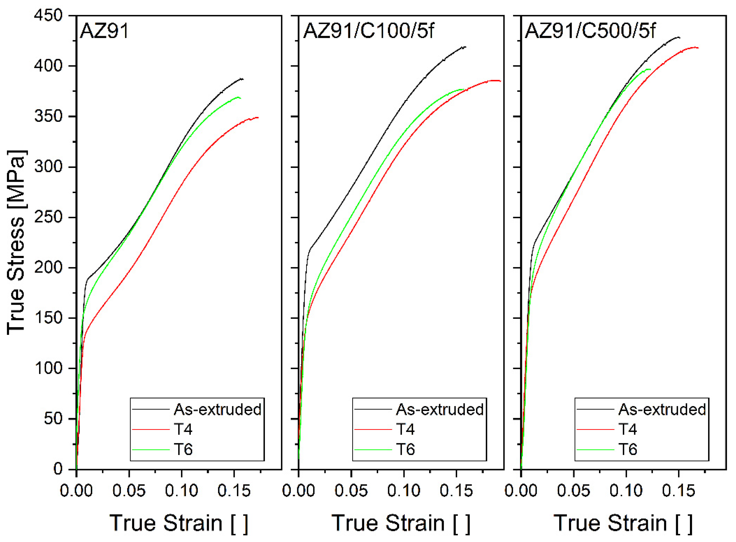
Figure 1. Compression curves showing true stress against true strain of AZ91 (left), AZ91/C100/5f (centre), and AZ91/C500/5f (right).
Crystals 12 01502 g001
Figure 2. BSE micrographs of the samples, taken with the extrusion direction horizontal across the page: (ac) AZ91, as extruded, T4, T6; (df) AZ91/C100/5f as extruded, T4, T6; (gi) AZ91/C500/5f as extruded, T4, T6. The composition of the numbered positions is provided in Table 2.
Crystals 12 01502 g002
Figure 3. Plots showing macroscopic true strain (left), strain on lattice planes (centre), and intensity (right) against true stress for (a) AZ91 as extruded; (b) AZ91 T4; (c) AZ91 T6.
Crystals 12 01502 g003
Figure 4. Plots showing macroscopic true strain (left), strain on lattice planes (centre), and intensity (right) against true stress for (a) AZ91/C100/5f as extruded; (b) AZ91/C100/5f T4; (c) AZ91/C100/5f T6.
Crystals 12 01502 g004
Figure 5. Plots showing macroscopic true strain (left), strain on lattice planes (centre), and intensity (right) against true stress for (a) AZ91/C500/5f as extruded; (b) AZ91/C500/5f T4; (c) AZ91/C500/5f T6.
Crystals 12 01502 g005
Figure 6. True stress against normalised intensity of the {00.2} planes for the as-extruded samples.
Crystals 12 01502 g006
Figure 7. True stress against normalised intensity of the {00.2} planes for unreinforced AZ91.
Crystals 12 01502 g007
Figure 8. The azimuthal distribution function at different strains for AZ91 as extruded. The units of intensity are multiples of random distribution.
Crystals 12 01502 g008
Figure 9. TVF of matrix against true strain for AZ91 (left), AZ91/C100/5f (centre), and AZ91/C500/5f (right).
Crystals 12 01502 g009
Table 1. Chemical composition of AZ91 alloy (wt %).
MgAlZnMnNdSiCaCuFe
Bal.8.730.670.210.0190.0190.00140.00270.0013
Table 2. Ultimate compressive stress and an estimate of the proof stress of samples (stress for 0.2% yielding). The proof stress was determined graphically using the deformation curve.
SampleUCS (MPa)Proof Stress (MPa)
AZ91 as extruded387190
AZ91 T4349135
AZ91 T6368162
AZ91/C100/5f as extruded419217
AZ91/C100/5f T4384153
AZ91/C100/5f T6377157
AZ91/C500/5f as extruded428219
AZ91/C500/5f T4418176
AZ91/C500/5f T6397184
Table 3. Composition from EDX analysis of positions marked on Figure 2.
ElementConcentration (wt %)
1234567
C4.145.16.63.274.38.2
N------9.5
O1.31.3-8.12.51.41.2
Mg88.85536.16.317.122.825.6
Al5.437.138.335.249-55.3
Si--0.60.70.2-0.2
Ca---0.4-1.5-
Mn--19.942.728.1--
Zn0.32.7-----
Table 4. Average grain size of samples in µm.
SampleAverage Grain Size (µm)
As ExtrudedT4T6
AZ917.6 (±2.2)19.0 (±4.1)19.4 (±9.8)
AZ91/C100/5f5.2 (±0.4)16.3 (±5.1)13.5 (±2.2)
AZ91/C500/5f5.5 (±0.4)11.1 (±1.6)12.6 (±3.5)
Table 5. TVF of the matrix at failure strain.
SampleTVF
AZ91 as extruded0.62
AZ91 T40.64
AZ91 T60.62
AZ91/C100/5f as extruded0.54
AZ91/C100/5f T40.59
AZ91/C100/5f T60.57
AZ91/C500/5f as extruded0.52
AZ91/C500/5f T40.54
AZ91/C500/5f T60.53
Publisher’s Note: MDPI stays neutral with regard to jurisdictional claims in published maps and institutional affiliations.