Article

Interfacial Microstructure and Mechanical Properties of Pressureless Sintered SiC Ceramic and Stainless Steel Joints Brazed by AgCu/AgCuTi Alloy

1
Key Laboratory of Advanced Welding Technology of Jiangsu Province, Jiangsu University of Science and Technology, Zhenjiang 212003, China
2
State Key Laboratory of Advanced Welding and Joining, Harbin Institute of Technology, Harbin 150001, China
*
Authors to whom correspondence should be addressed.
Crystals 2022, 12(11), 1574; https://doi.org/10.3390/cryst12111574
Submission received: 12 September 2022 / Revised: 27 October 2022 / Accepted: 29 October 2022 / Published: 4 November 2022
(This article belongs to the Special Issue Investigation on the Formation and Properties of Steels)

Abstract

:
A high-quality joint of pressureless sintered SiC ceramic (PS-SiC) and stainless steel brazed by AgCu/AgCuTi brazing alloy was realized. The effects of brazing temperature and holding time on the interfacial microstructure and mechanical properties of PS-SiC-stainless steel were analyzed. During brazing, Fe and Cr diffused into a brazing seam, and the typical interfacial microstructure of joints brazed at 890 °C for 15 min was stainless steel/Cr5Si3 + FeSi2 + Ag(s,s)/Cr5Si3 + FeSi2 + Ag(s,s) + Cu(s,s) + TiSi2 + TiC/FeSi2 + Ag(s,s) + Cu(s,s) + TiSi2/Ag(s,s) + Cu(s,s) + SiC/PS-SiC ceramic. Cu-Fe system improved the toughness of the joint, and the shear strength of the joint increased to ~67 MPa. With increasing brazing temperature and holding time, the element Fe continued diffusing into the brazing seam, and the uniformity of Cu-Fe system became worse. Then Cu(s,s) infiltrated into the surface layer of PS-SiC ceramic and FeSi2 brittle phase gathered in the brazing seam. Then, the brittleness of the joint increased and the shear strength of the joint decreased.

1. Introduction

Pressureless sintered SiC ceramic (PS-SiC) was regarded as one of the most promising ceramics due to its good properties, such as low density, light weight and good thermal shock resistance [1,2,3]. However, PS-SiC was difficult to processed into large and complex structural parts, resulting from its high hardness and brittleness, so the application of PS-SiC was limited. In order to extend the application of PS-SiC, PS-SiC was usually jointed with stainless steel [4,5]. The realization of PS-SiC-stainless steel joints will expand the application of PS-SiC ceramic in various fields, such as aerospace, transportation, chemical industry and power generation [6,7,8]. Hence, the jointing between PS-SiC and stainless steel was important and meaningful. Brazing was one of the most important method to joint ceramic and metal, recently [9,10]. During PS-SiC and stainless steel brazing with AgCuTi filler, two major problems were faced. Firstly, brazing alloy infiltrated into PS-SiC ceramic, leading to high residual stress in the joint. Secondly, Fe element diffused from stainless steel, aggregated, and formed a brittle compound. The mechanical properties then reduced, resulting from two problems.
Recently, for porous ceramic-metal and ceramic-stainless steel joints, scholars carried out some research. Zhao, Y.X. brazed porous Si3N4 ceramic and TiAl alloy with AgCu filler alloy. It was found that the penetration layer was first formed in the brazing process, and the penetration layer led the fracture to propagate in the porous Si3N4 ceramic substrate [11]. Sun, L.B. successfully brazed porous Si3N4 to Invar alloy using a CuTi brazing alloy, and revealed the influence of the brazing process on the microstructure evolution of the joint. The fracture propagation occurred in the P-Si3N4 ceramic substrate adjacent to the infiltration layer [12]. Then, Yao, Y.J. analyzed changing the composition of filler metal, brazing temperature and holding time of the TA1/304 stainless steel brazed joint. It revealed that the AgCuNi (70.75 Ag-28 Cu-1.25 Ni, wt.%) filler metal was selected to eliminate the excessive TixCuy and TixFey phases in the joint [13]. Xue, H.T. added graphite into the AgCuTi filler to improve the properties of the Al2O3/304 stainless steel joint. It was also found that the improvement of shear strength was attributed to the formation of TiC, which reduced the coefficient of thermal expansion (CTE) difference and refined the microstructure [14]. Lu, Y. researched the interfacial microstructure and properties of the Al2O3/K-52 austenitic stainless-steel brazed joint with a Ni-45Ti filler alloy. This explained that the bonding properties of the joint largely depend on the morphology of the TiC layer and diffusion region [15]. According to above research, it can be seen that porous ceramic/metal- and ceramic/stainless steel-brazed joints attracted much attention from scholars. The research mainly focused on the effect of Ti element and titanium compounds on the microstructure and mechanical properties of the joint. Meanwhile, in our paper, PS-SiC ceramic was firstly brazed with stainless steel, and the research mainly focused on the effect of the Cu-Fe system on the microstructure and shear strength of the joint.
Therefore, in this paper, PS-SiC ceramic was brazed with stainless steel with a AgCu/AgCuTi brazing alloy. The typical microstructure of the joint was analyzed. The effects of brazing temperature and holding time on the interfacial microstructure and mechanical properties of PS-SiC-stainless steel joints were also analyzed. Finally, the interfacial evolution mechanism of the joint and strengthening mechanism of the joints were clarified.

2. Experimental

The PS-SiC ceramic (obtained from Hyde precision ceramics Co., Ltd, Manchester, UK) contains more than 99.1 wt.% SiC micropowder. PS-SiC ceramics were cut into 5 mm × 5 mm × 5 mm pieces, and stainless steel (the chemical composition was in Table 1) was cut into 5 mm × 5 mm × 5 mm and 10 mm × 10 mm × 5 mm pieces for microstructure observation and mechanical testing, respectively. Ag-28Cu and Ag-21Cu-4.5Ti foils were used as a brazing alloy.
The PS-SiC ceramic and the cross-sections of the joints were cut by an automatic precision cutting machine (Shengyang Kejing Automation Equipment Co., Ltd, Shengyang, China). The microstructure of PS-SiC-stainless steel joints was analyzed by an emission scanning electron microscope (SEM, Helio Nanolab600i, Hillsboro, OR, USA) equipped with an energy dispersive spectrometer (EDS, INCA Energy 300, Oxfordshire, UK). An X-ray diffraction analysis (XRD, Bruker D8A A25, Berlin, Germany) was used to detect the phases in the brazing seams. During XRD measurement, the angle increment was 0.02° with 1000 W. The shear strength of the joint was tested by Electronic Universal Tester (Instron-1186, Instron, Shanghai, China) with a rate of 0.5 mm/min. Every five joints was a group, and the average value was the shear strength of the joint under the same conditions.
Before brazing, PS-SiC ceramic and stainless steel were polished by SiC paper of 400 #, 800 #, 1000 #, 1500 #, and were then cleaned ultrasonically in acetone for 10 min. The specimens were assembled in the order shown in Figure 1a. The specimens were then placed into a brazing furnace with a vacuum of 1.3–2.0 × 10⁻³ Pa. When the brazing temperature was below 880 °C, the Ag-28Cu/Ag-21Cu-4.5Ti brazing alloy was not able to fully fuse, due to the Fe element diffused into brazing seam. Meanwhile, when the brazing temperature was above 910 °C, the brittleness of the joint was high, due to the Fe element excessive diffusion into brazing seam. The brazing temperature range was thus selected from 880 °C to 910 °C. Firstly, the temperature was raised to 800 °C at a rate of 10 °C/min. Secondly, the temperature was further heated to the brazing temperature (T) at a rate of 5 °C/min, and held for brazing time (t). Finally, the specimens were cooled down to room temperature at a rate of 5 °C/min, as shown in Figure 1b. During shear testing, the schematic of the shear test fixture was shown in Figure 1c. Then, five repetitions were performed and the shear strength was determined by the average value of the five repetitions.

3. Results and Discussion

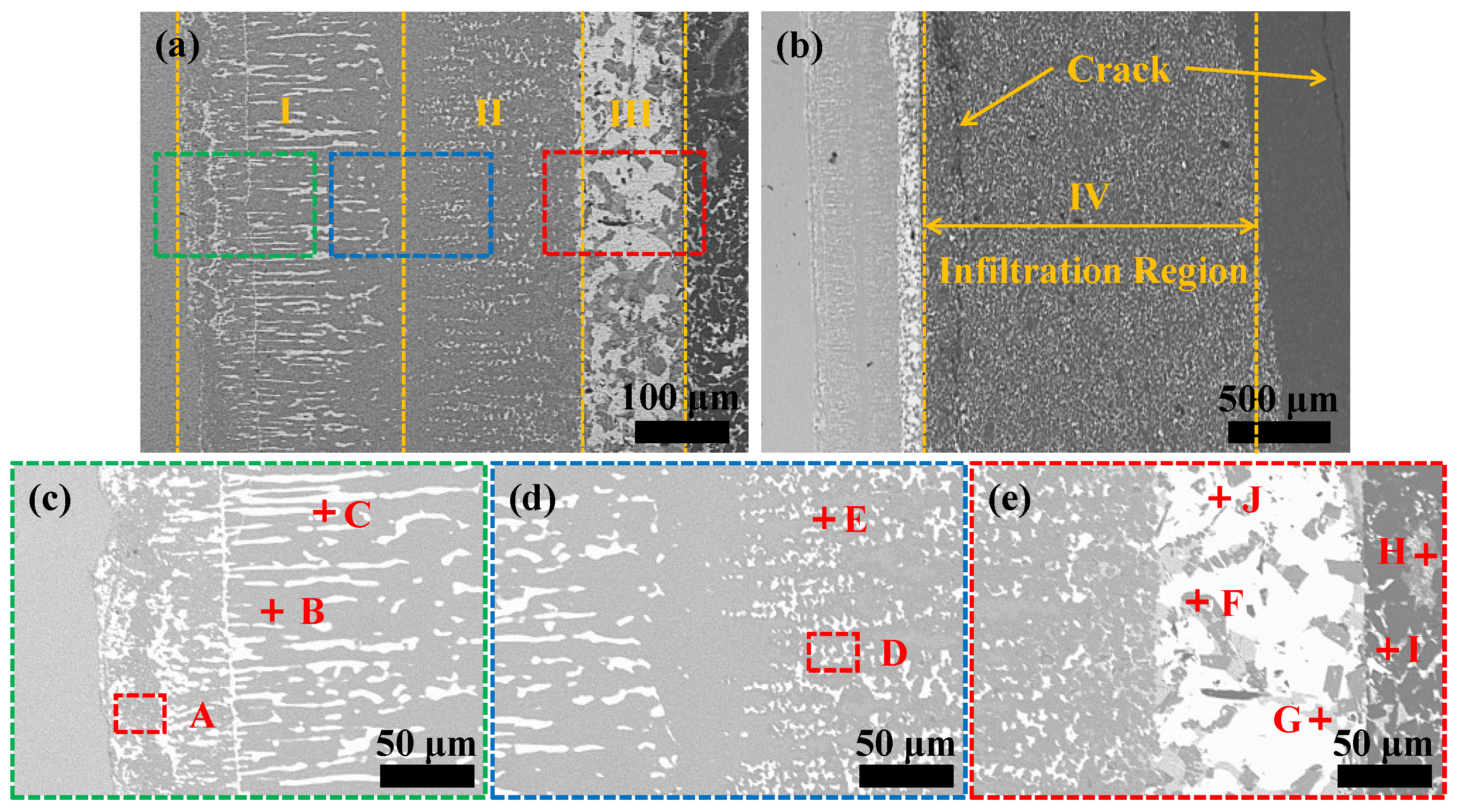
3.1. The Typical Microstructure of PS-SiC-Stainless Steel Brazed Joint

In order to investigate the microstructure of the joints in details, the magnification microstructure of a PS-SiC-stainless steel joint was shown in Figure 2. As shown in Figure 2a,b, the brazed joint was divided into four regions: Region I (diffuse region adjacent to stainless substrate); Region II (brazing seam); Region III (reaction zone adjacent to PS-SiC ceramic); and Region IV (infiltration zone in PS-SiC ceramic). It can be seen that cracks formed in Region IV, due to the large mismatch of CTE of brazing substrates (CTEstainless = 19.1 × 10⁻⁶ K−1, CTEPS-SiC = 2.98 × 10⁻⁶ K−1) and brazing alloy (CTEAgCuTi = 18.2 × 10⁻⁶ K−1) [16,17,18], so high residual stress formed and cracks emerged. The magnification microstructures of the three regions were shown in Figure 2c–e, respectively. The XRD pattern of PS-SiC-stainless steel joint was shown in Figure 3.
According to EDS (Table 2) and XRD (Figure 3) results, it can be inferred that Region I and Region II were mainly formed of Cr5Si3, FeSi2 and Ag(s,s), and that FeSi2, TiSi2, Ag(s,s) and Ag(s,s), Cu(s,s) were mainly distributed in Region III and Region IV, respectively. In order to further investigate the microstructure of PS-SiC-stainless steel joint, the main elements distribution of the joint was analyzed, as shown in Figure 4. It can be seen that Si and Ag were almost distributed in the whole joint. Fe and Cr diffused into Region I and Region II, and Cr was major in Region I. Cu and Ti were major in Region IV and Region III, respectively.

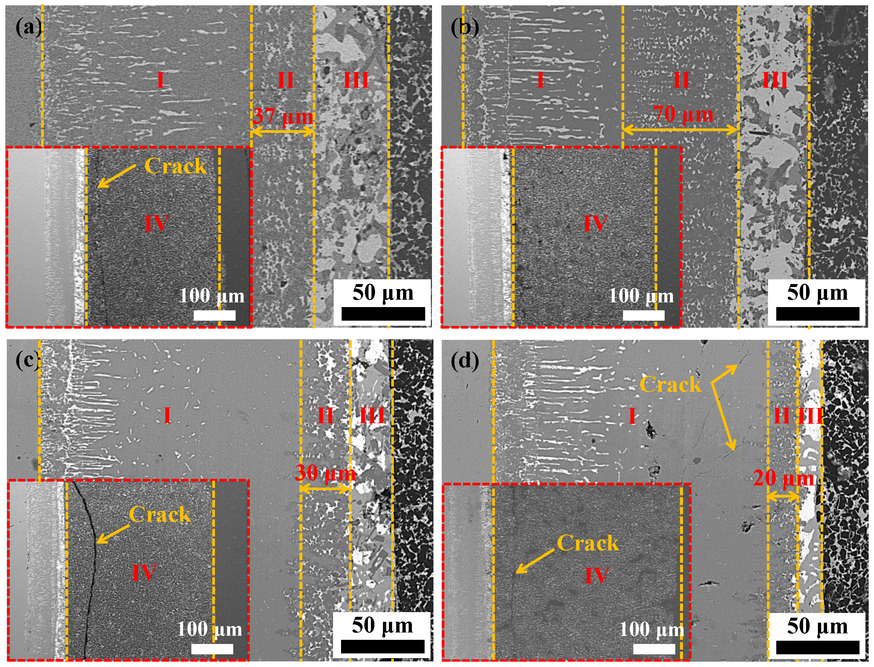
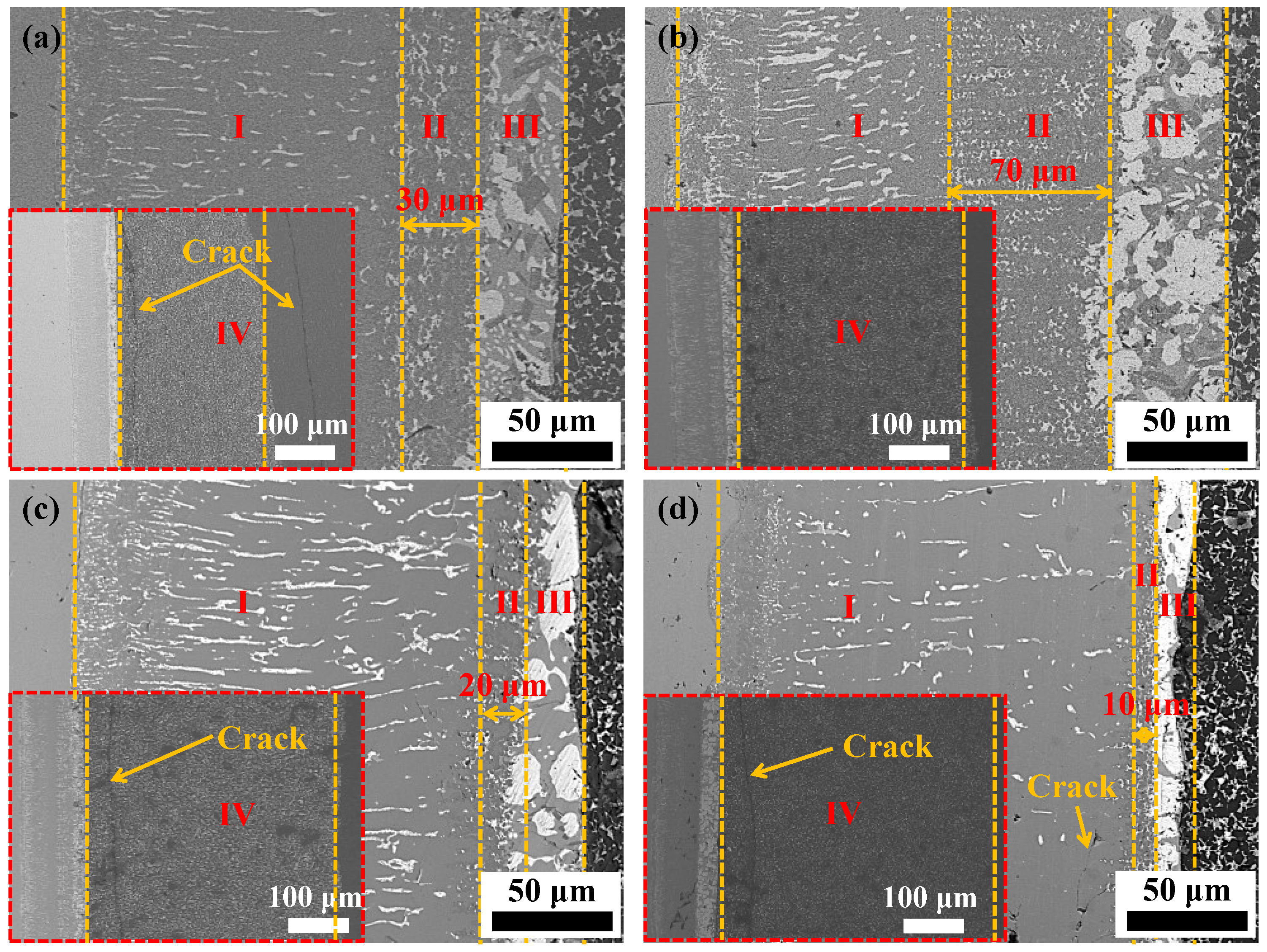
3.2. The Effect of Brazing Parameters on the Microstructure and Mechanical Property of the PS-SiC-Stainless Steel Joints

The influence of brazing parameters on the microstructure of the joint was obvious. Then, the effect of brazing temperature and holding time on microstructure and mechanical property of the joint was analyzed. Figure 5 presents the microstructure of PS-SiC-stainless steel joints brazed at different temperatures for 15 min. The morphology of PS-SiC-stainless steel joint changed substantially at different brazing temperatures. Brazing at a relatively low temperature of 880 °C, due to the limited dissolution of stainless steel substrate and slow atomic diffusion rate, the reaction between Fe and Ag-21Cu-4.5Ti was insufficient, and the thickness of the region was only 37 μm. The diffused Fe and Cr from stainless steel substrate reacting with PS-SiC ceramic produced FeSi2 and Cr5Si3, which distributed in the whole joint (see Figure 5a). With brazing temperature increased to 890 °C, the diffused Fe in the joint was adequate, and the thickness of Region II increased to 70 μm. Moreover, an abundant Cu(s,s) appeared in Region II, as the ratio of Cu and Fe was approximated to the uniformly mixed point of the Cu-Fe system (see Figure 5b). When the brazing temperature increased to 900 °C, the dissolution of Fe from stainless steel substrate was enhanced, and a large number of brittle FeSi2 agglomerated in Region II. Meanwhile, Cu(s,s) in Region II reduced, and extensive Ag-21Cu-4.5Ti brazing alloy infiltrated into the surface layer of PS-SiC ceramic (see Figure 5c). In addition, the continuous blocky intermetallic would reduce the capacity of the plastic deformation of the joint, so the shear strength of the joint reduced. When the temperature reached 910 °C, the temperature led to the further dissolution of Fe from the stainless steel substrate, and the concentration of FeSi2 in the brazing seam rapidly increased. A large amount of Ag-21Cu-4.5Ti brazing alloy infiltrated into the surface layer of PS-SiC, as shown in Figure 5d, so the shear strength of the joint further reduced (see Figure 6). However, Ag in the brazing seam had no involvement in the metallurgical reaction, and distributed in the whole joint.
From Figure 5a to Figure 5d, it can be seen that alongside the brazing temperature increasing, the thickness of Region IV increased, but the phases in Region IV were stable without changing. This was because Ti was mainly distributed in Region III and the remained brazing alloy infiltrated into Region IV; then, the phases were Ag(s,s) and Cu(s,s). It was worth noting that when the thickness of the Region IV was proper, the joint was good without cracks. Due to a good CTE gradient and tough phases forming in the joint with the proper thickness of Region IV, the residual stress was released and a high-quality joint of PS-SiC-stainless steel was realized.
Figure 7 shows the microstructure of the PS-SiC-stainless steel joints brazed for different times at 890 °C. As shown in Figure 7a, after brazing for 10 min, the dissolution of Fe from stainless steel substrate was limited, and the insufficient reaction between Fe and Ag-21Cu-4.5Ti brazing alloy led to the thickness of Region II being only 30 μm. The rest of Ag-21Cu-4.5Ti brazing alloy infiltrated into the surface layer of PS-SiC ceramic, and in addition, cracks formed in the joint, due to the large mismatch of CTE between PS-SiC ceramic and Ag-21Cu-4.5Ti brazing alloy. With increasing holding time to 15 min, the joint was good, and without defects such as cracks. For the holding time increasing, Fe adequately reacted with the Ag-21Cu-4.5Ti brazing alloy and PS-SiC ceramic substrate. The thickness of Region II then increased to 70 μm, resulting from the mass of FeSi2 and Cu(s,s). This means that the toughness of the joint was improved, and the shear strength of the joint increased (see Figure 7b and Figure 8). When the holding time increased to 20 min, the dissolution of Fe for stainless steel was enhanced, leading to the content of Fe in Region II increasing. The uniformity of Cu-Fe system became worse and Cu(s,s) infiltrated into the surface layer of PS-SiC ceramic substrate. Then, the abundant FeSi2 brittle phase remained in the brazing seam, and the shear strength of the joint reduced (see Figure 7c and Figure 8). When the holding time reached 25min, Fe excessively diffused from stainless steel substrate, and the FeSi2 brittle phase further increased, and even gathered. Thus, the shear strength of the joint decreased further (see Figure 7d and Figure 8). In addition, with holding time increasing, the thickness of Region IV increased. When the thickness of the Region was proper, a good gradient of CTE formed in the joint, and the shear strength of the joint was good.
According to the above analysis, it can be inferred that with brazing temperature and holding time increasing, Fe continuously spread from stainless steel and the content of Fe in Region II increased. When the ratio of Cu and Fe was unbalanced, the uniformity of the Cu-Fe system became worse and Cu(s,s) infiltrated into the surface layer of PS-SiC ceramic. Then, the FeSi2 brittle phase left in the brazing seam and the toughness of the joint decreased.

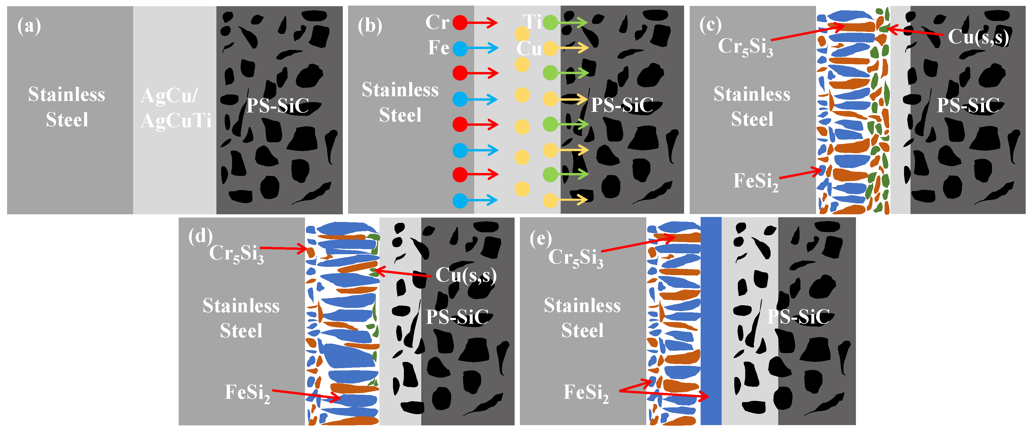
3.3. The Formation Mechanism of the PS-SiC-Stainless Steel Joints

The formation mechanism of the PS-SiC-stainless steel joint can be concluded from the above microstructure analysis, and the diagrammatic sketch is visualized in Figure 9. Before brazing, all the samples were assembled, and the cross-section was shown in Figure 9a. As the brazing temperature increasing to the melting temperature of the Ag-28Cu and Ag-21Cu-4.5Ti brazing alloys, the surface of the substrate was wetted by the molten filler, and the brazing alloy infiltrated into the surface layer of PS-SiC ceramic. Simultaneously, the element of Cr and Fe from stainless steel substrate began to diffuse, as shown in Figure 9b. Due to the advantageous thermodynamics of TiC production, Gibb’s free energy was −100 KJ/mol−1 at 890 °C [19]. Then, Si was liberated from PS-SiC ceramic during disintegration and diffused into the molten filler, where it reacted with Fe and Cr and formed FeSi2 and Cr5Si3. Meanwhile, the residual Fe reacted with Cu to produce a uniformly mixed Cu-Fe system, as shown in Figure 9c. As the brazing process proceeded, the diffusion of elements intensified further. The ratio of Cu and Fe was unbalanced in Cu-Fe system. Then, Cu(s,s) was put back in the brazing alloy and the FeSi2 phase became larger. Moreover, the brazing alloy continued to infiltrate into the surface layer of PS-SiC ceramic, as shown in Figure 9d. Figure 9e illustrated that PS-SiC ceramic and stainless steel were well jointed after brazing. The huge blocks of FeSi2 formed mainly from the reaction between diffused Fe and Si from substrates. As a result, due to huge blocks of FeSi2 forming in a joint, the shear strength of the joint reduced.

4. Conclusions

In this work, PS-SiC ceramic and stainless steel were successfully brazed by a Ag-28Cu/Ag-21Cu-4.5Ti brazing alloy. The effect of brazing temperature on interfacial microstructure and the mechanical property of the joints were systematically investigated. The conclusions obtained were as follows:
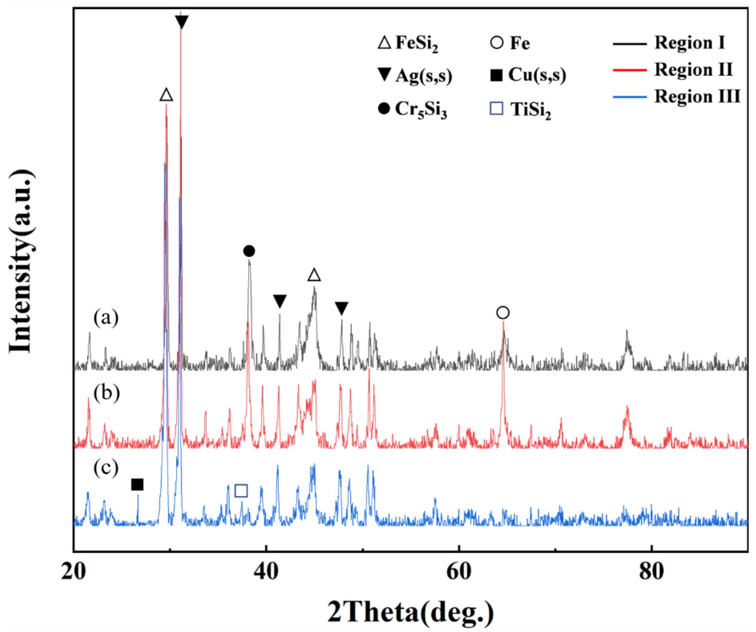
  • The typical microstructure of PS-SiC-stainless steel joint brazed at 890 °C for 15 min was stainless steel/Cr5Si3 + FeSi2 + Ag(s,s)/Cr5Si3 + FeSi2 + Ag(s,s) + Cu(s,s) + TiSi2 + TiC/FeSi2 + Ag(s,s) + Cu(s,s) + TiSi2/Ag(s,s) + Cu(s,s) + SiC/PS-SiC ceramic.
  • During brazing, Ag-21Cu-4.5Ti brazing alloy successively infiltrated into the Region IV, so the thickness of Region IV increased with the brazing temperature, and the holding time increased. Furthermore, the phases were Ag(s,s) and Cu(s,s) without new phases forming.
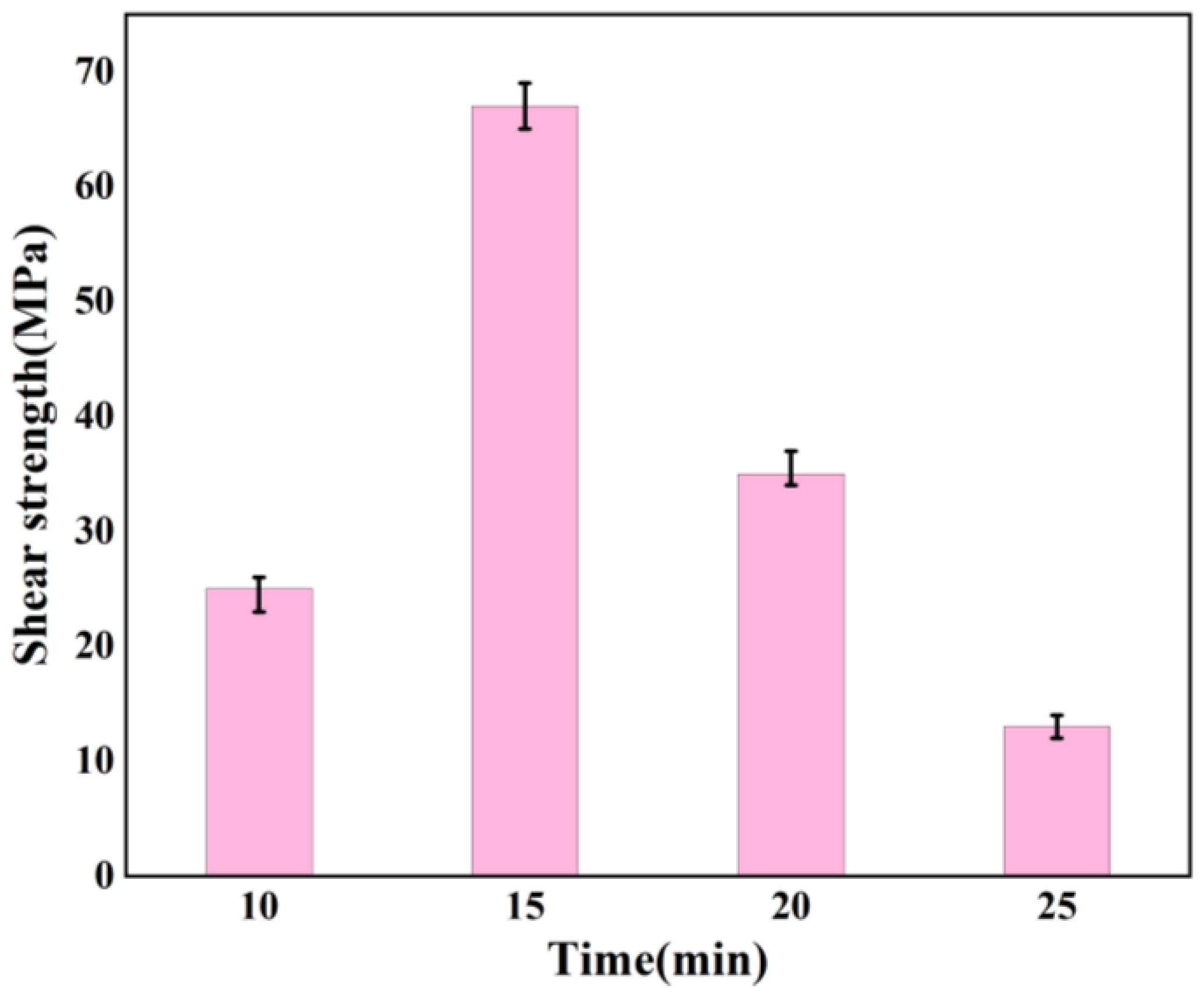
  • The shear strength of the joints increased with the brazing temperature and the holding time increased, and then decreased. The maximum shear strength of the joint was ~67 MPa when the joint was brazed at 890 °C for 15 min.
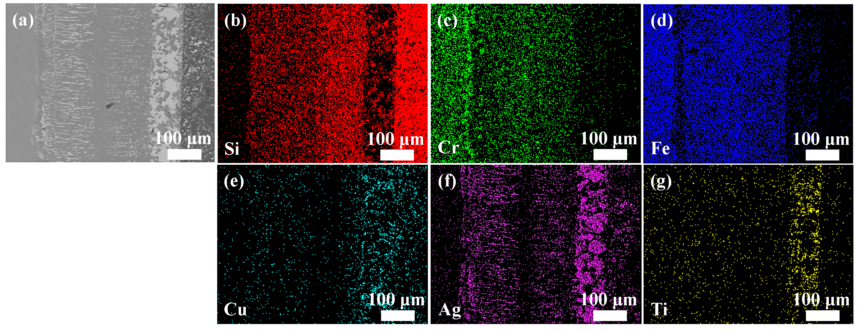
  • The increase in brazing temperature intensified the diffusion of element Fe, and Fe reacted with Cu to form Cu-Fe system at 890 °C for 15 min. The formation of Cu-Fe has increased both the toughness and the shear strength of the joint. When the brazing temperature and holding time increased further, the ratio of Cu and Fe was unbalanced, and the uniformity of the Cu-Fe system became worse. The grain size and volume of FeSi2 phase increased, and the brittleness of the joint increased. So, the shear strength of the joint decreased.

Author Contributions

Research was carried out by J.P., who helped me improve the writing of this paper, supported by the open research fund of State Key Laboratory of Advanced Welding and Joining (NO.AWJ-21M15). Q.M. supervised the experiment and wrote the paper, S.L., Y.C., carried out the experiment, and P.H. instructed in the experimental scheme. All authors have read and agreed to the published version of the manuscript.

Funding

This project is supported by National Natural Science Foundation of China (Grant NO. 52105350), State Key Laboratory of Advanced Welding and Joining (AWJ-23R01).

Institutional Review Board Statement

Not applicable.

Informed Consent Statement

Not applicable.

Data Availability Statement

Not applicable.

Conflicts of Interest

The authors declare no conflict of interest.

References

  1. Fang, J.; Qi, Q.; Sun, L.B.; Guo, S.S.; Shan, T.P.; Wen, Y.; Zhang, J.; Liu, C.F. Brazing SiC ceramic to Zircaloy-4 using Zr-Ni filler alloy: Microstructure, mechanical properties and irradiation behavior. J. Nucl. Sci. Technol. 2022, 564, 153715. [Google Scholar] [CrossRef]
  2. Shi, H.J.; Peng, H.B.; Chai, Y.D.; Li, N.; Wen, Y.H.; Bai, D.; Liu, Z.H.; Yan, J.Z.; Zhang, R.Q.; Li, M.; et al. Effect of Zr addition on the interfacial reaction of the SiC joint brazed by Inconel 625 powder filler. J. Eur. Ceram. Soc. 2021, 41, 6238–6247. [Google Scholar] [CrossRef]
  3. Luo, Z.Y.; Wang, G.; Zhao, Y.; Tan, C.W.; He, R.J. Brazing SiC ceramics and Zr with CoCrFeNiCuSn high entropy alloy. Ceram. Int. 2022, 48, 23325–23333. [Google Scholar] [CrossRef]
  4. Yan, Y.T.; Lin, J.H.; Liu, T.; Liu, B.S.; Wang, B.; Qiao, L.; Tu, J.C.; Cao, J.; Qi, J.L. Corrosion behavior of stainless steel-tungsten carbide joints brazed with AgCuX (X = In, Ti) alloys. Corros. Sci. 2022, 200, 110231. [Google Scholar] [CrossRef]
  5. Shu, X.P.; Li, K.; Li, Y.; Xiong, Z.Q.; Huang, Y.H.; Li, S.J. Experimental investigation on brazing residual stress distribution in 304L stainless steel core plate. J. Constr. Steel Res. 2022, 193, 107257. [Google Scholar] [CrossRef]
  6. Liu, X.; Chai, B.; Zhang, J.; Zhang, G.; Wang, W.; Qi, Y. Brazing of Ti-6Al-4V with a copper-based brazing filler metal. Weld. World 2021, 65, 1217–1223. [Google Scholar] [CrossRef]
  7. Cao, X.; Dong, K.; Zhu, R.; Wang, Q.; Kong, J. A high-strength vacuum brazed TC4/316L joint with a Ti-Zi based amorphous ribbon as the filler metal. Vacuum 2021, 187, 110070. [Google Scholar] [CrossRef]
  8. Xia, Y.; Dong, H.; Li, P. Brazing TC4 titanium alloy/316L stainless steel joint with Ti50-xZrxCu39Ni11 amorphous filler metal. J. Alloys Compd. 2020, 849, 156650. [Google Scholar] [CrossRef]
  9. Liao, M.Q.; Wang, F.J.; Zhu, J.C.; Lai, Z.H.; Liu, Y. P2221-C8: A novel carbon allotrope denser than diamond. Scripta Mater. 2022, 212, 114549. [Google Scholar] [CrossRef]
  10. Li, T.T.; Li, R.F.; Chang, T.; Ye, X.N.; Wang, F.J. Texture evolution and properties analysis of R60702 pure zirconium joint by fiber laser welding. Mater. Charact. 2021, 182, 111581. [Google Scholar] [CrossRef]
  11. Zhao, Y.X.; Song, X.G.; Hu, S.P.; Zhang, J.Y.; Cao, J.; Fu, W.; Feng, J.C. Interfacial microstructure and mechanical properties of porous-Si3N4 ceramic and TiAl alloy joints vacuum brazed with AgCu filler. Ceram. Int. 2017, 43, 9738–9745. [Google Scholar] [CrossRef]
  12. Sun, L.B.; Wei, Q.J.; Fang, J.; Liu, C.F.; Zhang, J. Brazing of porous Si3N4 ceramic to Invar alloy with a novel Cu-Ti filler alloy: Microstructure and mechanical properties. Ceram. Int. 2021, 47, 2068–2076. [Google Scholar] [CrossRef]
  13. Yao, Y.J.; Han, Y.; Zhang, K.Y.; Zhu, H.H.; Zhang, W.L.; Qian, H.L.; Zhou, C.S.; Zhang, L. The dependence of fracture mode on interfacial microstructure in TA1 pure titanium/AgCuNi/304 stainless steel vacuum brazed joints. Vacuum 2022, 203, 111318. [Google Scholar] [CrossRef]
  14. Xue, H.T.; Li, T.; Guo, W.B.; Chen, C.X.; Zhao, J.L.; Ding, Z.J. Effect of graphite content on microstructure and properties of Al2O3 ceramic and 304 stainless steel brazed joints. Mater. Lett. 2022, 307, 131050. [Google Scholar] [CrossRef]
  15. Lu, Y.; Wang, J.; Zheng, K.H. Interfacial microstructure and properties of Al2O3/K-52 austenitic stainless-steel-brazed joints based on the Ni-45Ti filler alloy. J. Manuf. Process. 2021, 68, 1303–1313. [Google Scholar] [CrossRef]
  16. Ma, Q.; Pu, J.; Li, S.G.; Chen, Y.W.; He, P. Introducing a 3D-SiO2-fiber interlayer for brazing SiC with TC4 by AgCuTi. J. Adv. Join. Process. 2022, 5, 100082. [Google Scholar] [CrossRef]
  17. Song, X.G.; Lei, Y.; Fu, W.; Luo, Z.K.; Li, H.L.; Long, W.M.; Hu, S.P. Brazing of super-hard AlMgB14-TiB2 ceramic to 304 stainless steel with AgCuTi filler alloy. Vacuum 2022, 197, 110810. [Google Scholar] [CrossRef]
  18. Dong, F.; Qie, J.M.; Deng, H.H. Study on thermal physical properties of 304 stainless steel at high temperature. In Recent Advances in Structural Integrity Analysis Proceedings of the International Congress; Elsevier: Amsterdam, The Netherlands, 2015; pp. 458–462. [Google Scholar]
  19. Zheng, Z.Y.; Wang, S.H.; Xu, M.Y.; Du, A.; Ma, R.N.; Fan, Y.Z.; Zhao, X.; Cao, X.M. Microstructure and mechanical properties of YG18 cemented carbide/40Cr steel joints vacuum brazed using Ag-Cu-Ti filler metal. Vacuum 2022, 204, 111323. [Google Scholar] [CrossRef]
Figure 1. The course of brazing PS-SiC-stainless steel: (a) assembly diagram; (b) process parameters; and (c) schematic of the shear test fixture.
Crystals 12 01574 g001
Figure 2. The typical microstructure of PS-SiC-stainless steel joint: (a) the microstructure of brazing seam; (b) complete microstructure of joint; and magnification drawing of (c) Region I; (d) Region II; and (e) Region III.
Crystals 12 01574 g002
Figure 3. XRD pattern of PS-SiC-stainless steel joint: (a) Region I; (b) Region II; and (c) Region III.
Crystals 12 01574 g003
Figure 4. (a) The microstructure of the joint and the distribution of main elements in the joint; (b) Si; (c) Cr; (d) Fe; (e) Cu; (f) Ag; and (g) Ti.
Crystals 12 01574 g004
Figure 5. Microstructure of the PS-SiC-stainless steel joints brazed at different temperatures for 15 min: (a) 880 °C; (b) 890 °C; (c) 900 °C; and (d) 910 °C.
Crystals 12 01574 g005
Figure 6. The shear strength of the joint brazed for 15 min at different temperatures.
Crystals 12 01574 g006
Figure 7. Microstructure of PS-SiC-stainless steel joints brazed for different holding times at 890 °C: (a) 10 min; (b) 15 min; (c) 20 min; and (d) 25 min.
Crystals 12 01574 g007
Figure 8. The shear strength of the joint brazed at 890 °C for different holding times.
Crystals 12 01574 g008
Figure 9. Schematic of the PS-SiC-stainless steel brazed joint formation mechanism.
Crystals 12 01574 g009
Table 1. The chemical composition of the stainless steel (at.%).
ModelCMnPSSiCrNiN
06Cr19Ni100.0820.0350.0150.7519100.1
Table 2. EDS compositional analyses result of the joints.
PositionComposition (at.%)Phase
AgCuTiFeCrSi
A12.599.300.2815.0530.8831.90Cr5Si3 + FeSi2
B6.619.816.8523.861.6051.27FeSi2
C92.541.79-0.240.474.96Ag(s,s)
D9.761.511.0629.802.5455.33FeSi2
E--1.0261.51.0136.47Fe + FeSi2
F3.141.550.1132.181.9761.05FeSi2
G9.7610.5426.801.511.5649.83TiSi2
H-92.453.62-3.530.40Cu(s,s)
I94.572.93-0.390.511.60Ag(s,s)
J93.743.23-0.280.362.39Ag(s,s)
Publisher’s Note: MDPI stays neutral with regard to jurisdictional claims in published maps and institutional affiliations.

