Article

The Influence of Shock Wave Surface Treatment on Vibration Behavior of Semi-Solid State Cast Aluminum—Al2SiO5 Composite

by
Paul Sureshkumar Samuel Ratna Kumar
1,
Peter Madindwa Mashinini
1,
Mahaboob Adam Khan
2,
Marimuthu Uthayakumar
2,3,*,
Ainagul Rymkulovna Toleuova
4,
Dariusz Mierzwiński
5,
Kinga Korniejenko
5 and
Mohd Shukry Abdul Majid
3
1
Department of Mechanical and Industrial Engineering Technology, University of Johannesburg, Johannesburg 2092, South Africa
2
School of Automotive and Mechanical Engineering, Centre for Surface Engineering, Kalasalingam Academy of Research and Education (KARE), Krishnankoil 626126, India
3
Faculty of Mechanical Engineering and Technology, University Malaysia Perlis (UniMAP), Kangar 02600, Malaysia
4
Faculty of Mechanical Engineering, Abylkas Saginov Karaganda Technical University, Ave. Nursultan Nazarbayev 56, Karaganda 100027, Kazakhstan
5
Faculty of Material Engineering and Physics, Cracow University of Technology, Jana Pawła II 37, 31-864 Cracow, Poland
*
Author to whom correspondence should be addressed.
Crystals 2022, 12(11), 1587; https://doi.org/10.3390/cryst12111587
Submission received: 14 October 2022 / Revised: 3 November 2022 / Accepted: 5 November 2022 / Published: 8 November 2022
(This article belongs to the Special Issue Semi-solid Processing: Fundamentals and Applications)

Abstract

:
The semi-solid state casting procedure was used to manufacture as-cast AA5083, 1 and 2 wt.% of aluminosilicate reinforced composite material. After solidification, developed as-cast materials were subjected to shock wave treatment in the subsonic wind tunnel. Various techniques were used to evaluate the change in shock wave exposure, including mechanical and structural analysis, which is a field dedicated to the study of vibrations and other material properties. The research methods involved developed material grain structure and surface morphology, such as field emission scanning electron microscope, X-ray diffraction, and the energy dispersive method. This study shows that the microhardness value of the matrix material is increased before and after exposure to shock wave treatment compared to the developed composite material. The natural frequency of the developed composite increases as a result of the addition of aluminosilicate reinforcement before and after the shock wave. In addition, the shifting of frequency mechanism is studied to know the influence of shock wave surface treatment. The results obtained show the potential of the application of this material in the area of robotic parts.

1. Introduction

In general, the robotic industries have set the pace for innovation and the establishment of innovative material structures and manufacturing advancements. The main developments in material innovation are weight loss, improved high availability, and lower costs [1,2,3]. For the past decades, typical robot structures have been made of aluminum (Al), titanium (Ti), metal, and polymer matrix composites. Due to challenges with composite stiffness, composite structures are being used in novel ways in robotic parts [1,2]. Robotic material has specific stiffness, and high density can be used to obtain quick maneuverability and high precision. If the material damping is high, the robot’s structural vibration can be diminished [4,5]. Steel and aluminum are not suitable materials for this purpose. Those metals possess relatively the same stiffness and poor damping properties, which makes them unsuitable for robotic structures. Composite materials, on the other hand, have a great amount of material damping and specific stiffness [4,6].
Aluminum metal matrix composite has shown to be a beneficial addition to innovative materials for improved performance in robotic and other applications [7,8]. Compared to other filler materials such as nanotubes, graphene, and fullerenes, the aluminosilicate particle (Al2SiO5 sub-micrometer size) particle has a wide range of industrial uses due to its high plate structure, aspect ratio, natural availability, and inexpensive cost [9,10,11]. The uniform dispersion behavior of the carbon-based nanomaterials inside the aluminum matrix material is challenging. The strong covalent bonding between the carbon particles results in cluster formation and this cluster formation will provide a non-uniformity of properties in the developed materials. Hence, the developed material will sustain the load in one direction and failure occurs in another direction. Additionally, the carbon-based nanoparticles are highly reactive to temperature, which leads to carbide (Al4C3) formation in aluminum matrix composite. This will increase the mechanical properties and decrease the vibration behavior of the material. Those filler particle materials have a lot of potential for improving material properties, but the cost of making them is considerable and dangerous [11,12]. Aluminosilicates are stacked as slabs, also called hydrous silicate minerals or very fine-grained particulates. Significant research focusing solely on the relevance and importance of aluminosilicates has been published in recent years. The key research fields are characterization, corrosion, improved strength properties of polymer composites, and vibration characteristics [13,14].
Many manufacturing methods used to develop aluminum metal matrix composites, such as powder metallurgy route, stir casting, compo-casting, and friction stir processing, are commonly used [15,16,17]. In these methods, casting is one of the most effective ways to develop aluminum matrix composites for real-time industrial applications. Any type of shape and size of components can be developed as a bulk product. Compo-casting is one of the major types of manufacturing methods, where reinforcement is added to the semi-solid state matrix material to create a uniform dispersion. This improves the interfacial bond between the matrix and the reinforcement material and enhances the surface property of the developed composite material [13,18,19].
Surface treatment is an important process requirement once the material is developed. This surface treatment can be divided into two types, heat treatment and cold working treatment. This changes the surface properties of the developed material by altering grain structure [20,21,22]. Apart from the traditional way of surface treatments, the shock wave has also been used to alter the surface property of the developed material. The technique to generate a hypersonic aerothermodynamic condition on the surface is to use shock wave tubes. The capabilities can produce a higher enthalpy stream at a temperature increase rate as high as a million K/s and enthalpies up to 45 MJ/kg in this type of ground facility [23]. This results in essential zones of the hypersonic flying system, such as the outer components, nose tip, and control surfaces undergoing rapid temperature increases, significant thermal gradients, non-ambient pressure conditions, dissociated gas from bow shock, and oxygen diffusion via the boundary layer [24]. Ground tests may be limited to shock wave tube material testing. Shock wave tubes were used to develop materials for manufacturing and evaluating materials under elevated working conditions. Materialists and metallurgy scientists explored the catalyst influence of CeO2 stabilized ZrO2 and observed phase transition utilizing a shock wave tube [25,26]. Researchers conducted shock wave tests on amorphous nanosized particles to reduce weight and develop 2nd-order nanostructures for aerospace applications. As a result, when a diffuse shock wave interacts with a solid or bulk material, it can change grain structure transformation, breaking of material bonding, forming diverse amorphous/crystalline phases, and/or oxidizing might occur [26,27,28]. In this work, aluminum alloy AA5083 was reinforced with sub-micrometer-sized aluminosilicate particles (Al2SiO5) using a compo-casting method. The developed composite has undergone a shock wave surface treatment to study the surface morphological changes using the field-emission scanning electron microscope (FE–SEM) and X-ray diffraction method (X-RD). Then the vibrational behavior of the as-cast and shock wave exposed matrix/composite were analyzed.

2. Materials and Methods

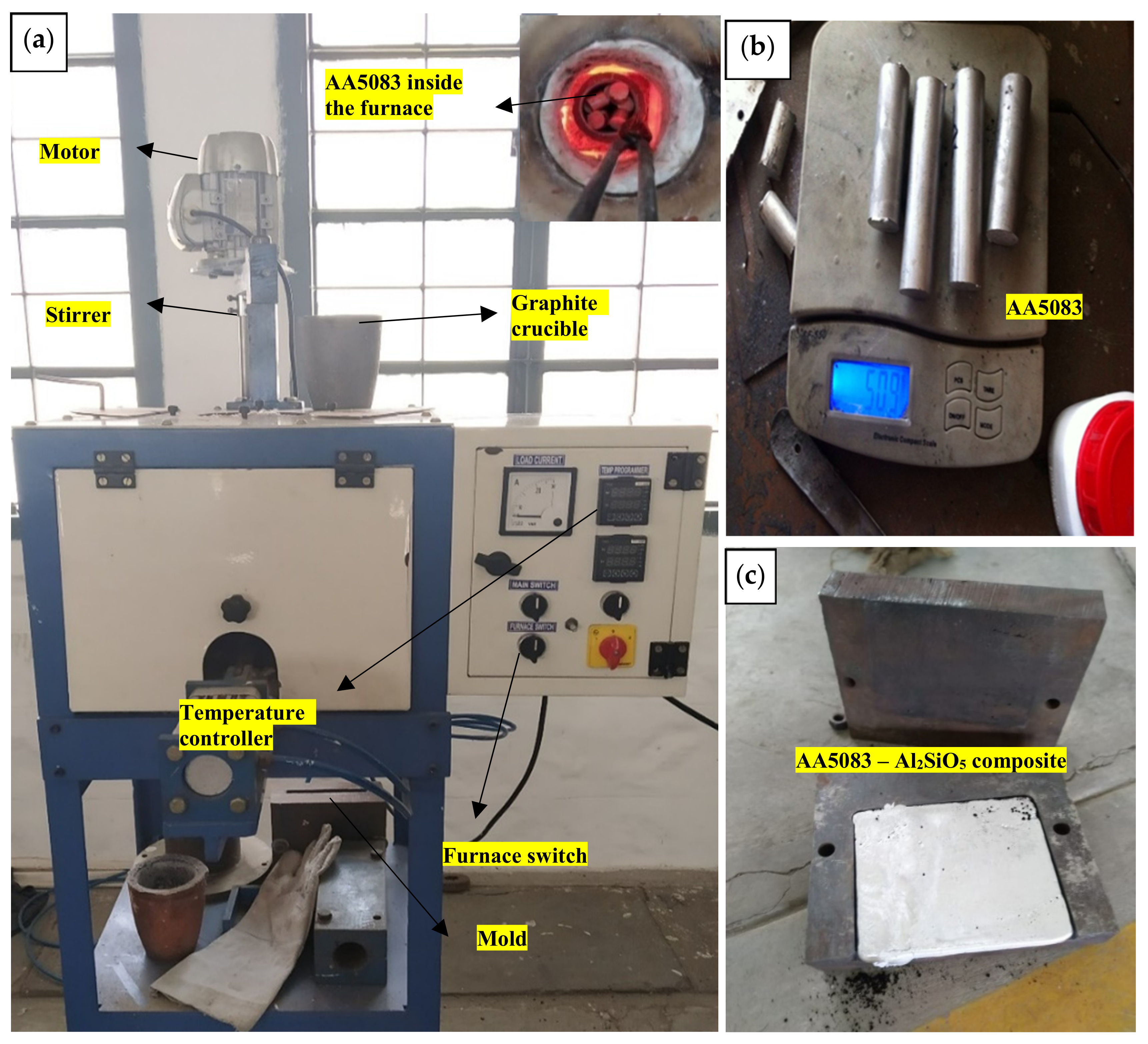
2.1. Semi-Solid State Casting Method

By varying the addition of aluminosilicate (Al2SiO5) sub-micrometer particles, aluminum metal matrix composites were developed. Figure 1 shows the casting equipment used to develop the composite material.
Previously, AA5083 matrix material was mixed with Al2SiO5 particles in various combinations such as 0, 1, and 2% by mass using the compo-casting method to avoid the poor wettability between the matrix and the reinforcement material. Figure 2 shows the structure of the Al2SiO5 particle used in this present work purchased from Sigma-Aldrich Co., St. Louis, Missouri, USA, layers of ~0.9 to 1.2 nm thick and stacked in ~9 to 11 µm as multilayer.
Before adding Al2SiO5 particles, it is placed in an alumina crucible and pre-heated to 770–774 K before being mixed along with the matrix material. The matrix material is semi-solidified, and a K-type thermocouple was used to monitor the semi-solid state temperature inside the graphite crucible of 860–864 K. The semi-solid state melt was then degassed for 2–3 min using nitrogen to prevent oxidation. To produce a homogeneous reinforcement dispersion, preheated Al2SiO5 was combined with the matrix material and stirred at a speed of 200–254 rpm for 3 min. The Al2SiO5 was mixed in semi-solid-state mixture of matrix material and poured into a mold (120 × 100 × 10 mm) to obtain uniform dispersed Al2SiO5 reinforced composites. During the casting process, slag formation was less due to controlling melting temperature, shortening molten aluminum transmission, and melting time. After the semi-solid-state melt was poured, melt was then solidified for 6–7 min at room temperature. AA5083—Al2SiO5 particle-reinforced composites employing the compo-casting process were prepared using similar procedures for the remaining composition (Table 1).

2.2. Shock Wave Surface Treatment

A one-of-a-kind experimental shock wave setup available in KCT, Coimbatore, Tamil Nadu, India, can shock the developed aluminum composite surface (120 × 100 × 10 mm), generating an energy flow that has a total enthalpy of 1.9 to 25.2 MJ/kg. Figure 3a shows the experimental setup, which provides an energy storage compartment with a piston. An aluminum membrane with a cutter head groove separates the compression tube from the shock tube, allowing the membrane to extend evenly during the fracturing process (Figure 3b). As illustrated in Figure 3c, a single aluminum composite plate was inserted at the end of the flange section to allow the core section of the composites to be revealed by resting inside the boundary condition and along the path of shock waves.
A pressure of 0.01 MPa was created in the storage part to keep the piston in place, whereas the shock tubes and compression were drained and filled with a pressure of 0.1 MPa clean helium and oxygen [27]. After that, the storage was compressed with nitrogen gas to a pressure of 1.9 MPa. As a result of the increased pressure and temperature, the aluminum membrane bursts due to a combination of very high temperature and pressure. Thus, the main shock wave pressure moves through the shock tube before rebounding by the aluminum composite plate. The reverted shock wave pressure causes a considerable boost in pressure by briefly stopping the flow. The experimental setup was fitted with piezoelectric pressure sensors and connected to a multichannel robust data-gathering device, which determined the duration. Figure 4 shows a graph of measured pressure and time signal by a data acquisition system.

3. Results and Discussion

3.1. Characterization of the Composite AA5083—Al2SiO5

Field-emission scanning electron microscope (FE–SEM) and X-ray diffraction method (X-RD) were used to investigate the characterization study of AA 5083- and AA 5083-reinforced Al2SiO5 composites before and after shock wave treatment. Figure 5a represents the energy-dispersive X-ray analysis (EDS) image of pure Al2SiO5 and its chemical elements presented before mixing it with the AA5083 material. The EDS image of the matrix material in alloy form and its chemical elements presented is shown in Figure 5b. The phase transition response within the prepared composites due to the inclusion of Al2SiO5 in the AA5083 material after the shock wave exposed along the surface was further studied using XRD analysis.
Figure 6 indicates the 2-phase shifts such as Al and Mg2Al3 phases of the as-cast matrix material after shock wave treatment. When 1 and 2 wt.% of Al2SiO5 are included in the AA5083 material, Figure 6 shows the Al, Mg2Al3, and Al2SiO5 phases present after the shock wave. In the authors’ previous work without shock wave treatment, the Si and Al2O3 were formed as individual phases when the Al2SiO5 layered reinforcement was added [18]. The chemical interface between the reinforcement and matrix is broken down when the shock wave was introduced. This is due to the high pressure generated by the shock wave that breaks the interface between the reinforcement and the matrix material. Hence, it was formed as a single Al2SiO5 formation which can be viewed in Figure 6. This single Al2SiO5 formation will improve the stiffness of the developed material.
Figure 7a–c shows the FE–SEM image of the matrix and composite material before shock wave treatment. Figure 7a shows the as-cast matrix material with larger and irregular grain structures and defects. The FE–SEM image of the surface morphology of the 1 and 2 wt.% reinforced composite material is shown in Figure 7b,c. It shows a good dispersion pattern of reinforcement material inside the matrix material. Mechanical bonding to chemical bonding was generated due to the semi-solid state casting process, which develops a good interface between Al2SiO5 and AA5083 [17,18]. In addition, some dislocations occurred because of the semi-solid state casting temperature. When the dislocation output circumstance is derived using the elastic theory, it can be represented in terms of a significant intensity factor of stress that occurred at the time of the casting process, which is highlighted in Figure 7b,c. Due to this, the surface property of the developed composites is decreased; rather, it enhances the stiffness behavior of the composites compared to the matrix material.
Figure 8a–c shows the FE–SEM image of the cast matrix and the composite material after shock wave treatment. Figure 8a shows the matrix material with a refined grain structure without defects. The shock wave impinges on the surface of the matrix material and enhances the grain structure to have better surface properties [26,27]. This results in a hardening of the surface of the matrix material. Figure 8b,c shows the surface morphology study of the Al2SiO5 reinforced composites after the shock wave surface treatment. A crack tip will excrete dislocations only when occurring stress is strong enough and the crack initiation along the material’s surface occurs due to the crack tip (main factor), which leads to dislocations. Hence, it was shown using the FE–SEM analysis (Figure 8b,c) along the surface of the developed material.
FE–SEM images show the breakage of the chemical bonding into mechanical bonding, resulting in a poor interface between the reinforcement and the matrix material. It occurred due to the shock wave impinging along the surface of the Al2SiO5-reinforced composites, where the high pressure broke the bonding and reduced the surface hardening property of the material compared to the matrix material [24,25,26,27]. Rather, it enhances the stiffness behavior of the material compared to the same composite materials before shock wave treatment. This improves the vibrational natural frequency of the material without losing its mechanical strength for SACRA robotic arm application.

3.2. Microhardness Property

Vickers microhardness testing equipment was used to determine the hardness of the matrix and composite material. The microhardness value varies according to the percentage of reinforcement weight of Al2SiO5 before and after shock wave treatment. Figure 9 shows that the maximum microhardness value was reached at 0 wt.%. The microhardness decreased as the amount of Al2SiO5 increased both before and after shock wave treatment.
The inclusion of Al2SiO5 in AA5083 material softens the as-cast composite materials. When Al2SiO5 was subjected to high temperatures beyond 1073 K, the particulates converted to a ceramic substance; the material transition occurred due to temperature impact. At the time of the semi-solid state casting process, the operating temperature was 860–864 K, less than 1073 K [18,28,29]. As a result of the inclusion of Al2SiO5 in the microhardness value of the AA5083 material, the composite material is reduced. Similarly, at the time of the shock wave, the high pressure and temperature reduce the chemical interaction between the AA5083 and Al2SiO5 in composite material as shown in Figure 10.
The chemical bond or interface between the matrix and reinforcement breaks due to the shock wave that impinges along the surface of the developed composites [27]. Additionally, the surface of the matrix material becomes hardened compared to that of the composite material due to the grain refinement that occurs due to the shock wave along the surface. Thus, the microhardness value of the composite material after the shock wave is decreased compared to the matrix material.

3.3. Vibration Frequency Response

The matrix and composite plate are stimulated with an impactor, and the impact scale is determined by the voltage differential in the hammer’s piezoelectric material, as illustrated in Figure 11.
During stimulation, the composite plate will impose frequencies, which may be detected with the help of an accelerometer attached to the center of the composite plate exposed to shock wave treatment. Underneath the constrained free-end situation, the free vibration response of base alloy and metal matrix composites was experimentally evaluated. The readings are determined by the location of the accelerometer sensor. Setting the accelerometer sensor to the place with the least amount of deformation may lead to a much more precise result [30]. Along with the center exposed to shock wave treatment, a maximum of nine points are collected in the shape of a 3 × 3 matrix, with three components occupying the horizontal edge and three elements occupying the lateral edge. The readings were gathered across all nine hammering and sensor sites and sent into the frequency response function analyzer as data [10,18,31]. The frequency analyzer then determines the proportion between the transverse spectra of the excitation and the frequency response. The natural frequencies of the Al2SiO5 composite plates were determined from the peak of the frequency response function. The natural frequency (Hz) values of free vibration of the matrix and Al2SiO5-reinforced materials before and after shock wave treatment for 3 nodes are shown in Figure 12, Table 2 and Table 3.
Compared to AA 5083 and 1 wt.% of Al2SiO5, the natural frequency values increased due to the addition of 2 wt.% Al2SiO5 before and after shock wave treatment. The presence of Si and Al2O3 at 2 wt.% nanoclay functions as a sheet, increasing stiffness regardless of the quasi-static value. Madeira et al. [32] discovered that the addition of particulates (Si and Al2O3) increased damping properties, indicating extrinsic and intrinsic damping processes. Compared to AA5083 before shock wave treatment, the impact of Al2SiO5 on the matrix material decreases the microhardness value of the material. This is due to the limited contact between molecules and matrix dislocations that occur at room temperature, causing friction between particulates. When there is internal force resistance in the grain boundary, the mechanical energy will change into thermal energy under cyclic loading conditions. This will be quantified as the material’s damping behavior. The Granato–Lucke mechanism revealed that the meeting point of the grain boundaries will be used as a pinning point and that the grain boundaries at the pinning point will operate as a vibration string [33].
Similarly, after the surface is exposed to a shock wave, the base and composite material show a reduction in microhardness value, with the increased pressure and temperature generated inside the shock wave tube, the aluminum membrane bursts due to a combination of very high temperature and pressure. Thus, the main shock wave pressure moves through the shock tube before rebounding by the aluminum composite plate. As a result of the high pressure and temperature developed at the time of the shock wave, the surface of the matrix material becomes hardened compared to that of the composite material. Thus, the friction between the Al2SiO5 particles/the matrix dislocation increases and frequency rises in composite material, resulting in a higher number of cycles per sec and better damping behavior. Furthermore, this high-pressure influence at the time of the shock wave reduces the chemical interaction between AA5083 and Al2SiO5 in composite material and has an impact on the damping properties of a material. Hence, the shock wave surface treatment increased the natural frequency of the developed composite material to avoid vibration failure for the dynamic SCARA robot arm applications.

4. Conclusions

The AA5083 material reinforced with Al2SiO5 sub-micrometer particles was uniformly dispersed using the compo-casting (semi-solid state) method. The surface morphology image of the developed as-cast matrix and composite material with FE–SEM shows some dislocations and the presence of reinforcement with a good interface within the matrix material. The as-cast materials effectively experienced a shock wave surface treatment using a shock wave tube. After experiencing the shock wave, the individual Al2SiO5 phase changes were observed in the X-RD analysis. FE–SEM images show the grain refinement in the matrix material and the chemical bonding between matrix/Al2SiO5 in composite material. This increases the surface hardness of the matrix and softens the surface of the composite material. The vibration behavior of the composite materials shows a better result compared to that of the matrix material before and after shock wave treatment. This shifting of frequency will resist the failure of the material at the dynamic conditions for the SCARA robotic arm application.

Author Contributions

Conceptualization, P.S.S.R.K. and P.M.M.; methodology, M.U. and P.M.M.; validation, D.M., A.R.T., M.U. and M.A.K.; formal analysis, D.M. and M.A.K.; investigation, P.S.S.R.K. and P.M.M.; resources, M.A.K. and M.U.; writing—original draft preparation, P.S.S.R.K. and P.M.M.; writing—review and editing, D.M., A.R.T., K.K. and M.S.A.M.; supervision, M.U., K.K. and M.S.A.M.; funding acquisition, M.U. and K.K. All authors have read and agreed to the published version of the manuscript.

Funding

This research received no external funding.

Institutional Review Board Statement

Not applicable.

Informed Consent Statement

Not applicable.

Data Availability Statement

Not applicable.

Acknowledgments

The authors express their gratitude to the administration of the University of Johannesburg, Johannesburg, South Africa, for their support of research. Additionally, we thank the Kumaraguru College of Technology, Coimbatore, Tamil Nadu, India, for using the shock wave tube facility.

Conflicts of Interest

The authors declare no conflict of interest.

References

  1. Kiyoto, I.; Hitonobu, K.; Katsuyuki, K.; Kenji, K. Observation of wear surface between pure PEEK and counterpart materials; titanium and 7075 aluminum alloy, in robot joint. Appl. Mech. Mater. 2013, 307, 347–351. [Google Scholar] [CrossRef]
  2. Dentler, D.R., II. Design, Control, and Implementation of a Three Link Articulated Robot Arm. Master’s Thesis, The University of Akron, Akron, OH, USA, 2008. [Google Scholar]
  3. Bisztyga-Szklarz, M.; Rząd, E.; Boroń, Ł.; Klimczyk, P.; Polczyk, T.; Łętocha, A.; Rajska, M.; Hebda, M.; Długosz, P. Properties of Microplasma Coating on AZ91 Magnesium Alloy Prepared from Electrolyte with and without the Borax Addition. Materials 2022, 15, 1354. [Google Scholar] [CrossRef] [PubMed]
  4. Dai, G.L.; Chang, S.L.; Hak, G.L.; Hui, Y.H.; Jong, W.K. Novel applications of composite structures to robots, machine tools and automobiles. Comp. Struct. 2004, 66, 17–39. [Google Scholar] [CrossRef]
  5. Mamalis, D.; Murray, J.J.; McClements, J.; Tsikritsis, D.; Koutsos, V.; McCarthy, E.D.; Brádaigh, C.M.Ó. Novel carbon-fibre powder-epoxy composites: Interface phenomena and interlaminar fracture behaviour, Compos. Part B Eng. 2019, 174, 107012. [Google Scholar] [CrossRef]
  6. Dai, G.L.; Kwang, S.J.; Ki, S.K.; Yoon, K.K. Development of the anthropomorphic robot with carbon fiber epoxy composite materials. Comp. Struct. 1993, 25, 313–324. [Google Scholar] [CrossRef]
  7. Saravana Mohan, M.; Samuel Ratna Kumar, P. Influence of CNT-based Nanocomposites in Dynamic Performance of Redundant Articulated Robot. Robotica 2021, 39, 153–164. [Google Scholar] [CrossRef]
  8. Belov, N.A.; Korotkova, N.O.; Dostaeva, A.M.; Akopyan, T.K. Influence of thermomechanical treatment on electrical resistivity and hardening of alloys Al–0.2% Zr and Al–0.4% Zr. Tsvetnye Met. 2015, 2015, 13–181. [Google Scholar] [CrossRef]
  9. Samuel Ratna Kumar, P.S.; Mashinini, P.M. Natural frequency study on AA7075—Aluminosilicate layered nanocomposites under T6 heat treatment condition. Mater. Today Proc. 2021, 46, 7069–7075. [Google Scholar] [CrossRef]
  10. Samuel Ratna Kumar, P.S.; John Alexis, S.; Saravana Mohan, M.; Edwin Sudhagar, P.; Sahith Reddy, M. Vibration—Impact study on AlMg4.5Mn reinforced nanoclay composites. Mater. Today Proc. 2020, 28, 1140–1143. [Google Scholar] [CrossRef]
  11. Gaaz, T.S.; Sulong, A.B.; Kadhum, A.A.H.; Al-Amiery, A.A.; Nassir, M.H.; Jaaz, A.H. The Impact of Halloysite on the Thermo-Mechanical Properties of Polymer Composites. Molecules 2017, 22, 838. [Google Scholar] [CrossRef]
  12. Shalomeev, V.; Tabunshchyk, G.; Greshta, V.; Nykiel, M.; Korniejenko, K. Influence of Alkaline Earth Metals on Structure Formation and Magnesium Alloy Properties. Materials 2022, 15, 4341. [Google Scholar] [CrossRef] [PubMed]
  13. Kumar, P.S.S.R.; Edwin Sudhagar, P.; John Alexis, S.; Subramani, M. Vibration Study on Aluminium Alloy 5083 Composite Reinforced with Montmorillonite. Trans. Indian Inst. Met. 2019, 72, 2449–2456. [Google Scholar] [CrossRef]
  14. Pandian, V.; Kannan, S. Processing and preparation of aerospace-grade aluminium hybrid metal matrix composite in a modified stir casting furnace integrated with mechanical supersonic vibration squeeze infiltration method. Mater. Today Commun. 2021, 26, 101732. [Google Scholar] [CrossRef]
  15. Chen, B.; Shen, J. Solid-state interfacial reaction and load transfer efficiency in carbon nanotubes (CNTs)-reinforced aluminum matrix composites. Carbon 2017, 114, 198–208. [Google Scholar] [CrossRef]
  16. Samuel Ratna Kumar, P.S.; Mashinini, P.M.; John Alexis, S. Metal matrix nanocomposites. In Nanotechnology in the Automotive Industry, 1st ed.; Song, H., Yasin, G., Gupta, R.K., Nguyen, T.A., Bahadur Singh, N., Eds.; Elsevier: Amsterdam, The Netherlands, 2022; Volume 1, pp. 199–213. [Google Scholar]
  17. Gladston, J.A.K.; Dinaharan, I.; Sheriff, N.M.; Selvam, J.D.R. Dry sliding wear behavior of AA6061 aluminum alloy composites reinforced rice husk ash particulates produced using compocasting. J. Asian Ceram. Soc. 2018, 5, 127–135. [Google Scholar] [CrossRef]
  18. Kumar, P.S.S.R.; Mashinini, P.M. Dry Sliding Wear Behaviour of AA7075—Al2SiO5 Layered Nanoparticle Material at Different Temperature Condition. Silicon 2021, 13, 4259–4274. [Google Scholar] [CrossRef]
  19. Dostayeva, A.; Toleuova, A. Physical and chemical interaction of aluminum with titanium and nickel for further use in parts of agricultural machinery. Eng. Rural. Dev. 2021, 20, 407–411. [Google Scholar] [CrossRef]
  20. Tiwari, S.K.; Soni, S.; Rana, R.S.; Singh, A. Effect of heat treatment on mechanical properties of aluminium alloy–fly ash metal matrix composite. Mater. Today Proc. 2017, 4, 176–183. [Google Scholar] [CrossRef]
  21. Manda, C.S.; Surendra Babu, B.; Ramaniah, N. Effect of heat treatment on mechanical properties of aluminium metal matrix composite (AA6061/MoS2). Latest Articles. Adv. Mater. Process. Technol 2021, 593. [Google Scholar] [CrossRef]
  22. Sam, M.; Radhika, N.; Pavan Sai, K. Effect of heat treatment on mechanical and tribological properties of aluminum metal matrix composites. Proc. Inst. Mech. Eng. Part C J. Mech. Eng. Sci. 2020, 234, 4493–4504. [Google Scholar] [CrossRef]
  23. Gai, S. Free piston shock tunnels: Developments and capabilities. Prog. Aerosp. Sci. 1992, 29, 1–41. [Google Scholar] [CrossRef]
  24. Bongiorno, A.; Först, C.J.; Kalia, R.K.; Li, J.; Marschall, J.; Nakano, A.; Opeka, M.M.; Talmy, I.G.; Vashishta, P.; Yip, S. A perspective on modeling materials in extreme environments: Oxidation of ultrahigh temperature ceramics. MRS Bull. 2006, 31, 410–418. [Google Scholar] [CrossRef] [Green Version]
  25. Vishakantaiah, J.; Reddy, K.P.J. Catalytic effect of CeO2-stabilized ZrO2 ceramics with strong shock-heated mono-and diatomic gases. J. Am. Ceram. Soc. 2016, 99, 4128–4136. [Google Scholar] [CrossRef]
  26. Reddy, N.K.; Jayaram, V.; Arunan, E.; Kwon, Y.-B.; Moon, W.J.; Reddy, K.P.J. Investigations on high enthalpy shock wave exposed graphitic carbon nanoparticles. Diam. Relat. Mater. 2013, 35, 53–57. [Google Scholar] [CrossRef]
  27. Kumar, P.S.S.R.; Mashinini, P.M.; Khan, M.B.A. Creep behaviour of shock-wave-surface treated aluminium–MWCNT nanocomposites. Emerg. Mater. Res. 2022, 11, 228–238. [Google Scholar] [CrossRef]
  28. Hosseyni Khorasgani, S.M.; Dashtbayazi, M.R. Mechanical property modeling of aluminium nanocomposite reinforced with carbon nanotubes. Emerg. Mater. Res. 2019, 8, 574–581. [Google Scholar] [CrossRef]
  29. Shahid, M.; Haafiz, M.; Kassim, M. Characteristic Properties of Nanoclays and Characterization of Nanoparticulates and Nanocomposites. In Nanoclay Reinforced Polymer Composites Engineering Materials; Springer: Berlin/Heidelberg, Germany, 2016; pp. 35–55. [Google Scholar]
  30. Natalia, L.; Robert, J. Experimental and Numerical Analysis of an Aluminum Cantilevered Beam with Polymer Adhesive. Proc. Eng. 2017, 172, 634–639. [Google Scholar] [CrossRef]
  31. František, K.; Soukup, J. Modal analysis of thin aluminium plate. Proc. Eng. 2017, 177, 11–16. [Google Scholar] [CrossRef]
  32. Madeira, S.; Miranda, G.; Soares, D.; Silva, F.S.; Caevalho, O. Study on damping capacity and dynamic Young’s modulus of aluminium matrix composite reinforced with SiC particles. Ciência Tecnol. Mater. 2017, 29, 92–96. [Google Scholar] [CrossRef]
  33. Clark, D.E.; Folz, D.C.; West, J.K. Processing materials with microwave energy. Mater. Sci. Eng. A 2000, 287, 153–158. [Google Scholar] [CrossRef]
Figure 1. Casting equipment: (a) experimental compo-casting setup; (b) matrix material; (c) AA5083—Al2SiO5 compound.
Crystals 12 01587 g001
Figure 2. FE–SEM image of aluminosilicate particles: (a) magnification 25 k×; (b) magnification 130 k×.
Crystals 12 01587 g002
Figure 3. Experimental equipment: (a) experimental setup; (b) fractured aluminum membrane; (c) fixed composite sample.
Crystals 12 01587 g003
Figure 4. Shock wave pressure measured using the data acquisition system.
Crystals 12 01587 g004
Figure 5. EDS analysis image: (a) aluminosilicate particle; (b) matrix material and its chemical elements.
Crystals 12 01587 g005
Figure 6. XRD analysis of AA5083- and Al2SiO5-reinforced material after shock wave treatment.
Crystals 12 01587 g006
Figure 7. FE–SEM image of the as-cast: (a) AA5083; (b) 1% by weight of Al2SiO5-reinforced composite materials; (c) 2% by weight of Al2SiO5 reinforced composite materials.
Crystals 12 01587 g007
Figure 8. FE–SEM image of the shock wave exposed: (a) AA5083; (b) 1 wt.% of Al2SiO5-reinforced composite materials; (c) 2 wt.% of Al2SiO5-reinforced composite materials.
Crystals 12 01587 g008
Figure 9. Microhardness of AA5083 and composite samples before and after shock wave treatment.
Crystals 12 01587 g009
Figure 10. Composite material with 2% by weight Al2SiO5 after exposure to shock wave.
Crystals 12 01587 g010
Figure 11. Vibration experimental setup with shock wave surface-treated sample.
Crystals 12 01587 g011
Figure 12. Natural frequency value before and after shock wave treatment.
Crystals 12 01587 g012
Table 1. Composition of the material AA5083.
ConstituentAlMgSiFeCuMnZnTiCr
wt.%Balance4.0–4.90.40.40.10.4–1.00.250.150.05–0.25
Table 2. Natural frequencies (Hz) before shock wave treatment.
NodeSample 1Sample 2Sample 3
1525550625
2162517501778
3360036803920
Table 3. Natural frequencies (Hz) after shock wave treatment.
NodeSample 1Sample 2Sample 3
1505632698
2161818101901
3358237454629
Publisher’s Note: MDPI stays neutral with regard to jurisdictional claims in published maps and institutional affiliations.

