Abstract
Zinc oxide, a direct band gap semiconductor of ≥3.30 eV, is prevalent in potential requests for energy devices. The early-stage demonstration of ZnO provides a new method of developing high ionic conductivity in multifunctional semiconductors for electrolyte applications in ceramic fuel cells (CFCs). In the present work, we successfully synthesized Na-doped ZnO nanorods by a hydrothermal method and employed them as an electrolyte in CFCs. The synthesized Na-doped-ZnO nanorods showed an effective ionic conductivity of 8.75 × 10⁻² S cm−1 along with an excellent power density of 609 mWcm−2 ± 5% when the fuel cell was operating at 550 °C. The enhanced ionic conductivity could be due to Na+ doping into Zn2+ and the high ionic radius of Na ions producing bulk oxygen vacancies in the ZnO structure to conduct oxygen ions or protons. Furthermore, we used experimental analysis, such as X-ray diffraction (XRD), high-resolution transmission electron microscopy (HR-TEM), scanning electron microscopy (SEM), ultraviolet–visible (UV–visible), X-ray photoelectron spectroscopy (XPS), and electrochemical impedance spectroscopy (EIS), to evaluate the change in structural properties and mechanism of ionic transport in ZnO nanorods with sodium doping. The presented work provides insight into a novel approach of developing the high ionic conductivity of electrolytes in a low-cost ZnO semiconductor material.
1. Introduction
The development of optimized ionic conductivity (oxide and proton) in a low-cost semiconductor-oxide has received growing interest due to their widespread application in ceramic fuel cells, including solid-oxide fuel cells (SOFCs) and proton ceramic fuel cells (PCFCs) [1]. Most often, yttria-stabilized zirconia (YSZ) is used as an electrolyte in commercially available state of the art SOFCs, which shows adequate ionic conductivities only at high temperatures (≥800 C) and adds many technical challenges in-terms of material selections and long-term operation, thus restricting the widespread application of CFC technology [2]. Developing an alternative electrolyte with good ionic conduction at intermediate temperatures (400–700 °C) is highly desirable [3]. Alternatively, doped barium cerates and zirconates-based perovskite oxides have receiving considerable attention in developing high proton conductivity at intermediate temperatures and have demonstrated high power outputs in PCFCs [4]. However, most proton-conducting electrolytes suffer poor chemical stability, e.g., in a H2 or H2O and CO2 atmosphere. Recently, materials with dual-ion conducting (O2−/H+) capabilities have been proposed as a new class of electrolytes for intermediate-temperature fuel cells, as they display low-ohmic, area-specific resistance, without external gas humidification [5,6,7].
Developing new electrolyte materials for application in CFCs has received much interest. Compared with the traditional concept, semiconductor electrolytes have multiple functionalities and transport channels for protons, oxygen ions, and electrons/holes. The feasibility of using these semiconducting oxides as an electrolyte has led to a new perspective and strategy for developing low-temperature CFCs. Therefore, a series of these individual ZnO-based semiconductors, or their semiconductor electrolytes, have been studied over the past few years due to their smaller energy band dispersions [8,9,10,11,12]. Following this, Xia et al. reported a p-n heterostructure of BaCo0.4Fe0.4Zr0.1Y0.1O3−δ-ZnO, which exhibited a remarkable ionic conductivity and fuel cell performance when operating at 450–500 C [13]. In our latest study, we introduced a semiconductor heterostructure consisting of p-type SrFe0.2Ti0.8O3 and n-type ZnO to evaluate as an electrolyte in LT-SOFCs with a favorable peak power density of 650 mW cm−2 at 520 C [14]. In other works, Xia et al. reported high ionic conductivity and power outputs in Li-doped ZnO and La/Pr-doped CeO2-ZnO heterostructures for electrolyte application with an appreciable performance at low operating temperatures [15,16]. These results, as mentioned earlier, indicate the potential application of a ZnO electrolyte in a fuel cell that can achieve promising power densities at a low operating temperature of 450–550 C, which are comparable to those of thin-film SOFCs using a pure ion-conducting electrolyte, e.g., YSZ.
However, further controlling the morphology and applying different doping contents may considerably increase ionic conductivity. Therefore, in this study, we synthesized Na-doped ZnO nanorods to improve zinc oxide’s proton and oxygen ion conductivity. The Na-doped ZnO nanorods were synthesized by incorporating a three-step design process: (i) coprecipitation, (ii) hydrothermal, and (iii) dry freezing techniques. The Na-doped ZnO powder was investigated in terms of morphological, chemical, and structural analysis. The Na doping in ZnO could produce more defects. These defects could be improved upon exposure to the H2 side in the fuel cell, which facilitated the ions’ migration followed by internal cavity development. Spontaneous ionic transportation was recorded in the developed Na-doped ZnO nanorods, revealing an optimum ionic conductivity up to 8.75 × 10⁻² S cm−1, along with a power density of 630 mW cm−2 when operating at 550 °C. The findings predict that the proposed strategy can potentially evolve novel materials with exceptional functionalities to fabricate highly effective PCFCs/SOFCs.
2. Materials and Methods
2.1. Synthesis Procedures
The nanorods of Na-doped ZnO were synthesized by following the three successive procedures. For this, zinc acetate (ZnC4H6O4) was bought from Shanghai Macklin Biochemical Co., Ltd., Shanghai, China, which had a purity level of up to 98.5%. First, 0.08 mole zinc acetate was dissolved into 500 mL of deionized (DI) water, followed by 0.02 moles of Na (NO3)2. We then added 6H2O into the solution. Similarly, a separate solution of (NH4)2CO3 was prepared by dissolving 0.2 moles of (NH4)2CO3 into 100 mL of DI water, which we poured drop-by-drop into the 500 mL solution containing ZnC4H6O4 and Na (NO3)2.6H2O. The resulting product of milky white precipitates were further transferred into a Teflon autoclave for hydrothermal treatment and placed at 220 C for 12 h using a vacuum oven. Consequently, a fine suspension was obtained and was washed with absolute ethanol/deionized water many times to avoid surface-adsorbed water. The obtained precursors were then dried via the dry-freezing method to evaporate the absorbed water. Lastly, the collected powders were calcined at 700 °C in the air for 4 h to obtain Na-doped ZnO nanorods. The multiple steps involved in synthesis are schematically described in Figure 1.
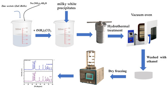
Figure 1.
Schematic diagram of different steps involved to synthesized Na-doped ZnO nanorods.
2.2. Characterization Tools and Electrochemical Measurements
The structural crystallinity of prepared Na-doped ZnO nanorods was analyzed by X-ray diffraction using a Bruker D8 Advanced X-ray diffractometer (Germany, Bruker Corporation with Cu Kα monochromator radiation bought from) with λ = 1.5418 Å in 2θ ranges of 10–80°. An FEI Tecnai GI F30 and a JEOL JSM7100F (resolution transmission electron microscopy), HR-TEM, and field emission scanning electron microscope (FE-SEM) were employed to investigate the microstructure, crystal structure, and chemical composition of the synthesized Na-doped ZnO. Furthermore, the chemical oxidation states were studied via X-ray photoelectron spectroscopy (XPS, Physical Electronics Quantum 2000, Al Kα X-ray source), and the raw data were obtained using CASA XPS software (2019 Casa Software Ltd.). The UV–visible absorption was measured using a UV–Vis 3600 spectrophotometer.
2.3. Fabrication of Fuel Cells
Herein, we employed a simple dry-pressing technique to construct solid fuel cell devices incorporating dense Na-doped ZnO nanorods electrolyte and porous Ni0.8Coi0.15Al0.05LiO2−δ (NCAL) electrodes. The layered structured NCAL powders acquired from Bamo Sci. & Tech. Joint Stock Company Ltd., Tianjin, China, were added into C10H18O to make a homogeneous slurry that was painted with a brush onto porous Ni foam. Afterward, the NCAL-painted Ni foam was dried in an oven at 120 °C for 2 h to use as an electrode. Finally, the synthesized ZnO and Na-doped ZnO nanorods powder were pressed between two NCAL/Ni foam electrodes in a steel mold with a diameter of 13 mm (pressure, 240 MPa) to fabricate solid fuel cell devices with a thickness of 1.0 mm and active-area 0.64 cm2. The performance of the as-fabricated fuel cell was determined via an ITECH8511dc electronic load instrument (ITECH Electrical Co., Ltd., new Taipei Taiwan) under H2, which acted as a fuel, and atmospheric air, which acted as an oxidant, with flow rates of 100–110 mL/min and 100 mL/min, respectively. The obtained I-V and I-P curves of the measured data are presented to show the electrochemical properties of the fabricated FC devices. A Gamry Reference 3000, USA workstation was used to measure electrochemical impedance spectroscopy (EIS) under open-circuit voltage (OCV) with 10 mV of DC signal over the frequency range of 0.1 to 106 Hz. The recorded data were analyzed using ZSIMPWIN software 3.2 AMETEK Scientific Instruments USA to obtained EIS data.
3. Results
3.1. Structure and Composition Analysis
Figure 2a illustrates the X-ray diffraction pattern of prepared pure ZnO and Na-doped ZnO nanorods. The main diffraction peaks of ZnO and Na-doped ZnO are positioned at 2θ° of the of the 31, 34, 36, 47, 56, 62, 67, and 68 planes, which could be well-indexed to the (100), (002), (101), (102), (110), (103), and (112) planes cross-ponds to the hexagonal wurtzite structure of ZnO [14,15]. No extra peaks in the Na-doped ZnO-sample patterns were observed, eliminating the possibility of additional phase formation after doping Na ions. The Na-doped ZnO sample showed a wurtzite structure phase, except for a small shift in the peaks toward a lower angle, possibly due to the large ionic radius of Na+ than Zn2+. Moreover, Rietveld refinement of the measured XRD data was performed using Prof-Suit software 2000 (Juan Rodríguez-Carvajal Laboratoire Léon Brillouin) for the sample with Na doping into ZnO. It showed a good fit to the experimental data and confirmed that Na-doped ZnO sustained a hexagonal wurtzite structure with a good fit factor of 2.04, as shown in Figure 2b. To verify the morphology of the rods and crystallography of synthesized ZnO and Na-doped ZnO nanorods, HR-TEM was used [16]. Figure 2c shows the morphology of Na-doped ZnO nanorods, which can clearly be associated with rods similar to the morphology of Na-doped ZnO. Moreover, Figure 2d,f shows the crystal spacing of pure ZnO and Na-doped ZnO, respectively. d-spacing values of 0.246 nm and 0.268 nm were calculated for pure ZnO and Na-doped ZnO, respectively, which correspond to the (100) plane. As discussed in the XRD data, the slight increase in the d-spacing value of Na-doped ZnO sample certainly occurred because of the larger ionic radius of Na+ than Zn2+. Moreover, the selected area electron diffraction (SAED) pattern was measured for Na-doped ZnO to study the diffraction pattern with multiple planes, as shown in Figure 2f, where the (100), (101), and (002) planes can be observed [17,18].
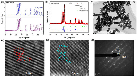
Figure 2.
(a) X-ray diffraction patterns of synthesized ZnO nanorods and 20% Na-doped ZnO nanorods, (b) Rietveld refinement of XRD data using Prof-Suit software for Na-doped ZnO nanorods, and (c) HR-TEM image of synthesized Na-doped ZnO nanorods. (d,e) Crystal structure and d-spacing of ZnO and Na-doped ZnO nanorods and (f) selected area of electron diffraction pattern of Na-doped ZnO.
Figure 3 shows SEM images of the synthesized Na-doped ZnO rods, revealing a sophisticated and fine morphology without agglomeration. The fine growth of ZnO nanorods and decreased formation of agglomerates were achieved due to the purity of the synthesis method [19,20]. Figure 3a–e shows the SEM image of Na-doped ZnO rods with different magnifications, such as 20 µm–2 µm. Moreover, energy dispersive spectroscopy (EDS) was employed to assess elemental mapping. Figure 3f shows the combined chemical distribution mapping of Na-doped ZnO for a single nanorod, revealing the uniform chemical distribution of Zn (yellow-colored), Na (pinkish), and O (green-colored). Furthermore, Figure 3g–i separately disclose the presence of each element, i.e., Zn, Na, and O in the Na-doped ZnO nanorods. The EDS mapping showed the presence of Na homogeneously doped into ZnO [21,22].
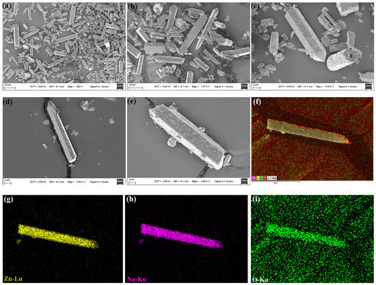
Figure 3.
(a–e) SEM image of Na-doped ZnO nanorods at different scales such as 20 µm–2 µm; (f–i) combined and individual EDS element mapping for Na, Zn, and O for the chemical composition of as-synthesized Na-doped ZnO nanorods.
3.2. Electrochemical Performance Measurements
To study the effectiveness of Na-doped ZnO nanorods in fuel cells, Na-doped ZnO and pure ZnO were used as ion-conducting electrolytes to measure electrochemical performance. Figure 4a shows the typical current–voltage (I-V) and associated power density (I-P) characteristics of fuel cells utilizing pure ZnO and our synthesized Na-doped ZnO material as an electrolyte operating at 550 °C. Our synthesized Na-doped ZnO electrolyte demonstrated an OCV of 1.13 V and a maximum power density (Pmax) of 610 mW cm2, in contrast to the Pmax of only 337 mW cm2 displayed by ZnO. This improvement of 273 mWcm−2 in power density was appreciable at our operating temperature of 550 C [23,24,25]. Additionally, as shown in Figure 4b, our prepared Na-doped ZnO electrolyte fuel cell showed excellent electrochemical performance even at low temperatures. At 500 and 450 °C, it showed peak power densities of 390 and 220 mW cm2, respectively. The improved electrochemical performance of the synthesized Na-doped ZnO-nanorods-based electrolyte over pure ZnO nanorods pointed to the critical importance of Na ion doping, which creates a highly oxygen deficient structure for establishing the path of oxygen ions or proton transport [23]. As a result, it can be concluded from the findings that Na-doped ZnO stoichiometry produced in three steps of synthesis may be useful in controlling the ionic properties of ZnO.
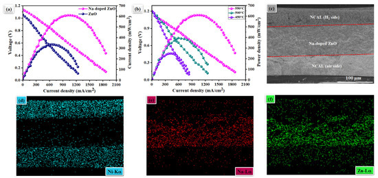
Figure 4.
(a) Typical I-V and I-P characteristic curve utilizing pure ZnO and Na-doped ZnO nanorods as an electrolyte in fuel cell operated at 550 °C; (b) fuel cell performance using our prepared Na-doped ZnO as an electrolyte under different operating temperatures of 450–550 °C; (c) cross-sectional SEM images of trilayer electrolyte supported symmetrical fuel cell along with prepared Na-doped ZnO electrolyte examined after the electrochemical test; (d–f) EDS mapping of Na-doped-ZnO electrolyte and Ni contents in NCAL electrode.
Figure 4c illustrates the cross-sectional SEM image of a Na-doped ZnO-based fuel cell after fuel cell operation, e.g., sintering and testing. It is evident from the SEM images that the fabricated Na-doped ZnO electrolyte layer was dense and tightly held by the adjacent anodes, without any cracks, after the operation of fuel cell performance. Such an adhesive and dense structure of the Na-doped ZnO electrolyte may guarantee no gas leakage and thus better fuel cell performance [23,26]. Moreover, Figure 4d–f show the EDS mapping of a cross-sectional SEM image of the Na-doped zinc-oxide-based fuel cell, where the distribution of Ni from the NCAL electrode at both edges of the cell and Na and Zn at the intermediate layer can be seen.
3.3. Electrochemical Impedance and Electrical Conductivity
Additionally, EIS characterizations of the cell with ZnO and Na-doped ZnO electrolyte were carried out in an atmosphere of H2 and air at 450–550 °C under OCV conditions. Figure 5a–c illustrates the measured EIS spectra’s Nyquist curve. The equivalent circuit modeling of Ro-(R1-CPE1)-(R2-CPE2) was carried out using ZSIMPWIN software 3.2 AMETEK Scientific Instruments USA (as shown in Figure 4b), where Ro is the ohmic resistance from the electrolyte; and R1 and R2 are the charge transfer and mass transfer losses from the electrode of the fuel cell with ZnO and Na-doped ZnO electrolyte, respectively. The EIS spectra showed that the Ro of the fuel cell with Na-doped ZnO significantly decreased in H2/air (fuel cell operating conditions) at a high temperature compared with a low temperature. For instance, a Na-doped ZnO electrolyte fuel cell showed a Ro of only 0.165 Ωcm2 in H2/air at 550 °C, while pure ZnO showed a Ro of more than 0.2 Ωcm2. Moreover, EIS characterizations of Na-doped ZnO were carried out at low operating temperatures, such as 500 and 450 C, where a Ro of 0.178 and 0.52 Ωcm2 were obtained, respectively. At low operating temperatures of 500 and 450 °C, a distinct difference in polarization loss (R1 and R2) values was also noticeable. Then, as observed for EIS results in Figure 5a–c, it dissolved the Na-doped ZnO electrolyte, reduced both ohmic and polarization losses, and helped to reduce the accumulation layer at the electrode–electrolyte interface, thus lowering the fuel cell’s charge transfer resistance (R1) and mass transport resistance (R2). The capacitance value could follow the mass and charge transfer value decrease at each cell’s electrode/electrolyte interface (i.e., R1∼C1 and R2∼C2), where capacitance can be determined by , where R corresponds to resistance, and n to Frequency power [0 ≥ n ≤ 1] of the Q’s values [11,24,25,27,28].
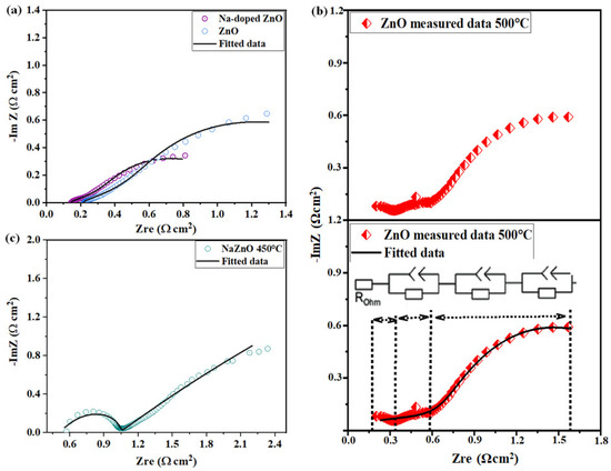
Figure 5.
(a) Comparison of the impedance spectra of undoped and Na-doped ZnO electrolyte cell operating at 550 °C in H2/air. (b,c) Impedance spectra for the fuel cell with prepared Na-doped ZnO electrolyte layer measured in H2/air at 500 and 450 °C, respectively.
3.4. Spectroscopic Analysis
The ionic conductivity of the synthesized ZnO nanorods and Na-doped ZnO from EIS in fuel cells was evaluated using the Ro values of the fitted data. As shown in Figure 6a, the ionic conductivity of synthesized Na-doped ZnO nanorods was 8.75 × 10⁻² S cm−1, which was appreciable at this operating temperature. Because it is difficult for oxygen ions or protons to move through the bulk structure of ZnO, the ZnO-based electrolyte showed poor ionic conductivity. Our conductivity results confirm the findings that Na-doped ZnO produces a more deficient ZnO structure and supports rapid ionic transport. These results indicate that synthesized Na-doped ZnO nanorods by three-step methods may be a good candidate for electrolyte application in advanced ceramic fuel cells [20].
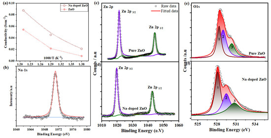
Figure 6.
(a) The electrical conductivity of ZnO and Na-doped ZnO electrolyte measured from EIS; (b–f) X-ray photoelectron spectra of Na-1s, Zn-2p, and O1s spectra of as-synthesized pure ZnO and Na-doped ZnO nanorods, respectively.
Furthermore, X-ray photoelectron spectroscopy was used to study the electrotonic and surface properties of pure ZnO and Na-doped ZnO. High-resolution XPS spectra were fitted using the mixture function of Lorentzian and Gaussian after Shirley’s background was removed. Prior to the following electrochemical performance measurements, we were interested in observing the chemical and electronic state configuration changes of the Na-1s, Zn-2p, and O1s. Figure 6b shows the XPS spectra of the Na-1s in Na-doped ZnO. The XPS spectra of Zn-2p (1/2, 3/2) for pure ZnO and Na-doped ZnO nanorods are shown in Figure 6c,d, respectively. The central peak of Zn-2p of pure ZnO appeared at a binding energy of 1022.38/1044.2 eV, while after Na-doping into ZnO nanorods, they appeared at a binding energy of 1021.8/1043.42eV. The XPS spectra of Zn-2p (1/2, 3/2) showed a shift toward a lower binding energy after Na doping. The Zn-2p spectrum presented an overall change of ≅0.6 5 eV to lower binding energies, which is usually related to the formation of nonstoichiometric or oxygen deficiency because of oxygen vacancies produced by Na doping. Additionally, a material’s O1s spectra impact a material’s ionic conductivity [29,30]. The O1s XPS spectrum of pure ZnO and Na-doped ZnO nanorods showed a lop-sided peak, indicating the presence of different oxygen species levels. The curve was fitted to three distinct peaks (1, 2, and 3), as shown in Figure 6e,f. Peak 1 centered at 528.1 eV and could be attributed to O2− ions bonded to Zn-O and Na-O of the wurtzite structure of Zn2+, whereas the second peak (peak 2) situated at 529.2 eV could be assigned to oxygen defects/vacancies, supporting the supposition of forming more nonstoichiometric Na-doped ZnO. Finally, peak 3 appeared at 530.8 eV and could be correlated to weak oxygen bonds on the surface, such as OH groups. Increased oxygen vacancies, crucial for high fuel cell performance, are indicated by an enhanced area percentage ratio of Olat/Ovac of Na-doped ZnO compared to pure ZnO [21,28]. As a result, our developed Na-doped ZnO nanorods may offer a new approach to producing high-performance LT-SOFC electrolyte materials. [31]. This indicates that the Na-doped ZnO has more oxygen vacancies than pristine ZnO. Figure 6 schematically illustrates the process for configuring a deficient Na-doped ZnO layer necessary for the mobility of oxygen and proton ions [31].
Moreover, from previous practice, ceramic fuel cells using NCAL symmetrical electrodes exhibit better electrochemical performance in the temperature range of 450 to 600 °C. In reality, NCAL at the anode side is reduced by H2 to produce a Li2CO3 or Li-OH species mixture and diffuses into the electrolyte, which produces high ionic conductivity. In this way, the amount of Li-OH or Li2CO3 produced by NCAL after H2 reduction and diffusion through the electrolyte particles forms a core–shell composite electrolyte. However, the partial melting and softening of Li2CO3/LiOH at an operating temperature of 450–500 °C could also be another reason for the high performance of Na-doping into ZnO. A similar mechanism was also reported for CeO2, TiO2 and ZrO2 [32]. The final step, the fuel cell’s electrochemical and ionic transport mechanism, is shown in Figure 7.
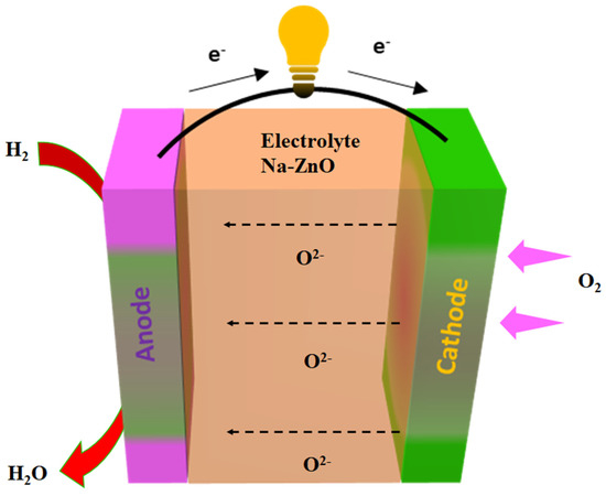
Figure 7.
The different electrochemical mechanisms and processes involved in fuel cells with Na-doped ZnO-nanorods-based fuel cells for ionic transport mechanism in Na-doped zinc oxide.
4. Conclusions
In summary, we successfully synthesized and characterized a Na-doped ZnO nanorods material. Additionally, the synthesized nanorods of Na-doped ZnO were employed as electrolytes in fuel cells and exhibited exceptional fuel cell performance and an ionic conductivity of 8.75 10−2 S cm−1. At 550 °C, the fuel cell with prepared ZnO as the electrolyte demonstrated a high-power density of 610 mW cm2. Additionally, we investigated the mechanism underlying the upsurge in ionic conductivity of Na-doped ZnO-nanorods in comparison to pure ZnO using microscopic and spectroscopic analyses. We noticed that synthesized Na-doped ZnO nanorods showed low-ohmic, area-specific resistance, and Na doping formed an oxygen-deficient structure that assisted with O2− transport. Moreover, the XPS findings and characteristics of Na-doped ZnO’s structural change were clearly described. In conclusion, this technique might be the inspiration to form novel oxygen-ion-conducting electrolytes based on zinc oxide, which may benefit all energy devices and material systems.
Author Contributions
The conceptualization of this work was completed by Y.S. and J.X.; N.M. and J.Q. finished the methodology; formal analysis and investigation by L.L. and J.X.; J.X. and Y.S. provided the resources and data curation facilities. Y.S. did the original draft preparation. Reviewed and edited by N.M., M.A.K.Y.S. and J.Q. All authors have read and agreed to the published version of the manuscript.
Funding
We thank the School of Electronic Engineering, Nanjing Xiaozhuang University, 211171 Nanjing, China, for providing experimental facilities. This study was supported by the National Natural Science Foundation of China (NSFC) under grants #51772080 and 11604088 and Southeast University (SEU PROJET # 3203002003A2).
Data Availability Statement
The data supporting this study’s findings are available from the corresponding authors upon reasonable request.
Acknowledgments
We acknowledge the Department of Electronic Engineering, Huainan Union University, Huainan, China, for providing experimental facilities and publication charges.
Conflicts of Interest
The authors declare no conflict of interest.
References
- Duan, C.; Kee, R.J.; Zhu, H.; Karakaya, C.; Chen, Y.; Ricote, S.; Jarry, A.; Crumlin, E.J.; Hook, D.; Braun, R.; et al. Highly durable, coking and sulfur tolerant, fuel-flexible protonic ceramic fuel cells. Nature 2018, 557, 217–222. [Google Scholar] [CrossRef] [PubMed]
- Choi, S.; Kucharczyk, C.J.; Liang, Y.; Zhang, X.; Takeuchi, I.; Ji, H.-I.; Haile, S.M. Exceptional power density and stability at intermediate temperatures in protonic ceramic fuel cells. Nat. Energy 2018, 3, 202–210. [Google Scholar] [CrossRef]
- Malavasi, L.; Fisher, C.A.J.; Islam, M.S. Oxide-ion and proton conducting electrolyte materials for clean energy applications: Structural and mechanistic features. Chem. Soc. Rev. 2010, 39, 4370–4387. [Google Scholar] [CrossRef] [PubMed]
- Goodenough, J.B. Oxide-Ion Conductors by Design. Nature 1999, 404, 821–823. [Google Scholar] [CrossRef] [PubMed]
- Mastour, N.; Ramachandran, K.; Ridene, S.; Daoudi, K.; Gaidi, M. Tailoring the optical band gap of In–Sn–Zn–O (ITZO) nanostructures with co-doping process on ZnO crystal system: An experimental and theoretical validation. Eur. Phys. J. Plus 2022, 137, 1137. [Google Scholar] [CrossRef]
- Bi, L.; Da’As, E.H.; Shafi, S.P. Proton-conducting solid oxide fuel cell (SOFC) with Y-doped BaZrO3 electrolyte. Electrochem. Commun. 2017, 80, 20–23. [Google Scholar] [CrossRef]
- Hakim, M.; Yoo, C.-Y.; Joo, J.H.; Yu, J.H. Enhanced durability of a proton conducting oxide fuel cell with a purified yttrium-doped barium zirconate-cerate electrolyte. J. Power Sources 2015, 278, 320–324. [Google Scholar] [CrossRef]
- Muccillo, R.; Muccillo, E.N. Synthesis and Properties of BaZr0.1Ce0.7Y02−xMxO3−δ (x = 0, 0.1; M = Dy, Yb) Compounds. ECS Trans. 2011, 35, 1251. [Google Scholar] [CrossRef]
- Liu, Z.; Zhou, M.; Chen, M.; Cao, D.; Shao, J.; Liu, M.; Liu, J. A high-performance intermediate-to-low temperature protonic ceramic fuel cell with in-situ exsolved nickel nanoparticles in the anode. Ceram. Int. 2020, 46, 19952–19959. [Google Scholar] [CrossRef]
- Shah, M.Y.; Mushtaq, N.; Rauf, S.; Akbar, N.; Xing, Y.; Wu, Y.; Wang, B.; Zhu, B. Advanced fuel cell based on semiconductor perovskite La–BaZrYO3−δ; as an electrolyte material operating at low temperature 550 °C. Int. J. Hydrog. Energy 2020, 45, 27501–27509. [Google Scholar] [CrossRef]
- Shah, M.A.K.Y.; Rauf, S.; Mushtaq, N.; Zhu, B.; Tayyab, Z.; Yousaf, M.; Hanif, M.B.; Lund, P.D.; Lu, Y.; Asghar, M.I. Novel Perovskite Semiconductor Based on Co/Fe-Codoped LBZY (La0.5Ba0.5Co0.2Fe0.2Zr0.3Y0.3O3−δ) as an Electrolyte in Ceramic Fuel Cells. ACS Appl. Energy Mater. 2021, 4, 5798–5808. [Google Scholar] [CrossRef]
- Lu, Y.; Mi, Y.; Li, J.; Qi, F.; Yan, S.; Dong, W. Recent Progress in Semiconductor-Ionic Conductor Nanomaterial as a Membrane for Low-Temperature Solid Oxide Fuel Cells. Nanomaterials 2021, 11, 2290. [Google Scholar] [CrossRef]
- Xia, C.; Mi, Y.; Wang, B.; Lin, B.; Chen, G.; Zhu, B. Shaping triple-conducting semiconductor BaCo0.4Fe0.4Zr0.1Y0.1O3−δ into an electrolyte for low-temperature solid oxide fuel cells. Nat. Commun. 2019, 10, 1707. [Google Scholar] [CrossRef]
- Kamran Yousaf Shah, M.A.; Mushtaq, N.; Rauf, S.; Xia, C.; Zhu, B. The semiconductor SrFe0.2Ti0.8O3−δ-ZnO heterostructure electrolyte fuel cells. Int. J. Hydrog. Energy 2019, 44, 30319–30327. [Google Scholar] [CrossRef]
- Xia, C.; Qiao, Z.; Shen, L.; Liu, X.; Cai, Y.; Xu, Y.; Qiao, J.; Wang, H. Semiconductor electrolyte for low-operating-temperature solid oxide fuel cell: Li-doped ZnO, International. J. Hydrog. Energy 2018, 43, 12825–12834. [Google Scholar] [CrossRef]
- Xia, C.; Qiao, Z.; Feng, C.; Kim, J.-S.; Wang, B.; Zhu, B. Study on Zinc Oxide-Based Electrolytes in Low-Temperature Solid Oxide Fuel Cells. Materials 2018, 11, 40. [Google Scholar] [CrossRef]
- Stevens, J.; Wieczorek, W.; Raducha, D.; Jeffrey, K. Proton conducting gel/H3PO4 electrolytes. Solid State Ionics 1997, 97, 347–358. [Google Scholar] [CrossRef]
- Yashima, M.; Tsujiguchi, T.; Sakuda, Y.; Yasui, Y.; Zhou, Y.; Fujii, K.; Torii, S.; Kamiyama, T.; Skinner, S.J. High Oxide-Ion Conductivity through the Interstitial Oxygen Site in Ba7Nb4MoO20-Based Hexagonal Perovskite Related Oxides. Nat. Commun. 2021, 12, 556. [Google Scholar] [CrossRef]
- Wang, B.B.; Zhong, X.X.; He, C.L.; Zhang, B.; Cvelbar, U.; Ostrikov, K. Solvent-dependent structures and photoluminescence of WO3−x nanomaterials grown in nonaqueous solutions. J. Alloy. Compd. 2021, 854, 157249. [Google Scholar] [CrossRef]
- Wang, Z.; Fan, X.; Li, C.; Men, G.; Han, D.; Gu, F. Humidity-sensing performance of 3DOM WO3 with controllable structural modification. ACS Appl. Mater. Interfaces 2018, 10, 3776–3783. [Google Scholar] [CrossRef]
- Shah, M.Y.; Rauf, S.; Zhu, B.; Mushtaq, N.; Yousaf, M.; Lund, P.D.; Xia, C.; Asghar, M.I. Semiconductor Nb-Doped SrTiO3−δ Perovskite Electrolyte for a Ceramic Fuel Cell. ACS Appl. Energy Mater. 2021, 4, 365–375. [Google Scholar] [CrossRef]
- Mushtaq, N.; Xia, C.; Dong, W.; Wang, B.; Raza, R.; Ali, A.; Afzal, M.; Zhu, B. Tuning the energy band structure at interfaces of the SrFe0.75Ti0.25O3−δ–Sm0.25Ce0.75O2−δ heterostructure for fast ionic transport. ACS Appl. Mater. Interfaces 2019, 11, 38737–38740. [Google Scholar] [CrossRef] [PubMed]
- Wang, B.; Cai, Y.; Xia, C.; Kim, J.S.; Liu, Y.; Dong, W.; Wang, H.; Afzal, M.; Li, J.; Raza, R.; et al. Semiconductor-ionic membrane of LaSrCoFe-oxide-doped ceria solid oxide fuel cells. Electrochim. Acta 2017, 248, 496–504. [Google Scholar] [CrossRef]
- Shah, M.A.K.Y.; Zhu, B.; Rauf, S.; Mushtaq, N.; Yousaf, M.; Ali, N.; Tayyab, Z.; Akbar, N.; Yang, C.P.; Wang, B. Electrochemical properties of a co-doped SrSnO3−δ-based semiconductor as an electrolyte for solid oxide fuel cells. ACS Appl. Energy Mater. 2020, 3, 6323–6333. [Google Scholar] [CrossRef]
- Mushtaq, N.; Lu, Y.; Xia, C.; Dong, W.; Wang, B.; Shah, M.Y.; Rauf, S.; Akbar, M.; Hu, E.; Raza, R.; et al. Promoted electrocatalytic activity and ionic transport simultaneously in dual functional Ba0.5Sr0.5Fe0.8Sb0.2O3−δ-Sm0.2Ce0.8O2−δ heterostructure. Appl. Catal. B Environ. 2021, 298, 120503. [Google Scholar] [CrossRef]
- Wang, J.; Lu, Y.; Mushtaq, N.; Shah, M.Y.; Rauf, S.; Lund, P.; Asghar, M.I. Novel LaFe2O4 spinel structure with a large oxygen reduction response towards protonic ceramic fuel cell cathode. J. Rare Earths 2022, 4–31. [Google Scholar] [CrossRef]
- Shah, M.Y.; Tayyab, Z.; Rauf, S.; Yousaf, M.; Mushtaq, N.; Imran, M.A.; Lund, P.D.; Asghar, M.I.; Zhu, B. Interface engineering of bi-layer semiconductor SrCoSnO3−δ-CeO2−δ heterojunction electrolyte for boosting the electrochemical performance of low-temperature ceramic fuel cell. Int. J. Hydrog. Energy 2021, 46, 33969–33977. [Google Scholar] [CrossRef]
- Chen, G.; Liu, H.; He, Y.; Zhang, L.; Asghar, M.I.; Geng, S.; Lund, P.D. Electrochemical mechanisms of an advanced low-temperature fuel cell with a SrTiO3 electrolyte. J. Mater. Chem. A 2019, 7, 9638–9964. [Google Scholar] [CrossRef]
- Katrib, A.; Hemming, F.; Wehrer, P.; Hilaire, L.; Maire, G. The multi-surface structure and catalytic properties of partially reduced WO3, WO2 and WC + O2 or W + O2 as characterized by XPS. J. Electron Spectrosc. Relat. Phenom. 1995, 76, 195–200. [Google Scholar] [CrossRef]
- Efkere, H.I.; Gümrükçü, A.E.; Özen, Y.; Kınacı, B.; Aydın, S.Ş.; Ates, H.; Özçelik, S. Investigation of the effect of annealing on the structural, morphological and optical properties of RF sputtered WO3 nanostructure. Phys. B Condens. Matter. 2021, 622, 413350. [Google Scholar] [CrossRef]
- Wang, B.; Zhu, B.; Yun, S.; Zhang, W.; Xia, C.; Afzal, M.; Cai, Y.; Liu, Y.; Wang, Y.; Wang, H. Fast ionic conduction in semiconductor CeO2−δ electrolyte fuel cells. NPG Asia Mater. 2019, 11, 1–12. [Google Scholar] [CrossRef]
- Dai, R.; Chen, G.; Wei, K.; Chen, Z.; Lv, X.; Liu, G.; Li, Y.; Geng, S. Effect of chemical reactions between electrolyte and lithium compounds on the electrochemical performance of the ceramic fuel cells. Carbon Resour. Convers. 2022, 5, 131–138. [Google Scholar] [CrossRef]


Publisher’s Note: MDPI stays neutral with regard to jurisdictional claims in published maps and institutional affiliations. |
© 2022 by the authors. Licensee MDPI, Basel, Switzerland. This article is an open access article distributed under the terms and conditions of the Creative Commons Attribution (CC BY) license (https://creativecommons.org/licenses/by/4.0/).