Article

Nanofiber Sr2Fe1.5Mo0.5O6-δ Electrodes Fabricated by the Electrospinning Method for Solid-Oxide Cells

1
School of Energy and Power Engineering, Nanjing University of Science and Technology, 200 Xiaolingwei Street, Nanjing 210094, China
2
School of Chemistry and Chemical Engineering, China University of Mining and Technology, 1 Daxue Street, Xuzhou 221116, China
*
Authors to whom correspondence should be addressed.
Crystals 2022, 12(11), 1624; https://doi.org/10.3390/cryst12111624
Submission received: 29 September 2022 / Revised: 10 November 2022 / Accepted: 10 November 2022 / Published: 12 November 2022
(This article belongs to the Special Issue Advances of Solid Oxide Fuel Cells)

Abstract

:
Solid oxide cells (SOCs) are attracting much more attention as promising energy conversion and storage devices. One of the challenges of optimizing of solid-oxide cells’ performance is that there are not enough triple-phase boundaries (TPB) in the electrode bulk. To enhance the reaction area for SOCs, Sr2Fe1.5Mo0.5O6-δ nanofibers are synthesized by electrospinning with metal nitrate precursors and used for SOC electrodes operated in both humidified air and a hydrogen atmosphere. SFMO nanofibers display a highly porous and crystallized perovskite structure and continuous pathways by XRD analysis and SEM observation. The average diameter of the SFMO nanofibers after sintering is about 100 nm. The La0.8Sr0.2Ga0.8Mg0.2O3-δ(LSGM) electrolyte-supported symmetrical cell with the SFMO nanofiber electrode exhibits enhanced electrochemical performance in humidified air and an H2 atmosphere. Moreover, a distribution of the relaxation time method is used to analyze the impedance spectra, and the polarization peaks observed are assigned to correspond different electrochemical processes. The results indicate that the SFMO nanofiber with an improved nanostructure can be the potential material for the SOC electrode.

1. Introduction

Alleviating the increasing concern over problems of environment and energy production requires drastic modification of our energy system: moving from fossil fuels to low-carbon energy sources. Due to the intermittent characteristics of renewable energy sources, such as wind and solar energy, long-term energy storage and efficient energy conversion technology are urgently needed. Solid-oxide cells (SOCs) are promising energy conversion technology, which can produce electrical energy in solid-oxide fuel cells (SOFCs) and can also store excess energy into chemical fuels in solid-oxide electrolysis cells (SOECs) [1,2,3,4].
The electrode reaction’s rates have been experimentally and numerically proven to be dependent on the microstructure of the electrodes since the chemical and physical steps proceed at the electrode’s surface and the electrode–electrolyte interface [5,6]. Specifically, the electrochemical performance relies on the porosity and length of the TPB [6,7,8], which are determined by the material synthesis and electrode fabrication techniques [9,10]. Among them, the nanostructured electrode materials are suggested to accelerate the penetration of fuel into the bulk and obtain prolonged TPBs in SOCs [11,12,13].
Electrospinning has been applied to the synthesis of ceramic nanofiber materials for the application of SOC electrodes because it provides an enlarged specific surface area, a continuous conduction pathway, and a highly porous structure [14,15,16]. Hieu et al. [17] electrospun the Ba0.5Sr0.5Co0.8Fe0.2O3-δ(BSCF) nanofiber and prepared a symmetrical cell on the GDC electrolyte, leading to an 80% reduction in area-specific resistance compared to the powder-based electrode. Chen et al. [18] fabricated (La0.6Sr0.4)0.95Co0.2Fe0.8O3-δ(LSCF) nanofibers and demonstrated that the unique architecture formed by electrospinning promotes mass/charge transport in ORR kinetics. Furthermore, an anode-supported single-cell configuration of NiO−YSZ|YSZ|GDC|LSCF/CeO2 with the LSCF/CeO2 composite nanofiber cathode fabricated by Zhang et al. [19] only had 0.031 Ω·cm2 at 700 °C, which exhibited highly active and robust stability. Therefore, many materials, especially mixed ion-electron conductors (MIECs), have been electrospun and used as electrodes. The adoption of nanofiber-based electrodes has enabled performance enhancement compared to powder-based electrodes.
One of MIEC candidate materials is the double-perovskite molybdenum-doped strontium ferrite [20,21,22]. Ana B et al. [23] investigated the formation of oxygen vacancies in the Sr2FeMoO6-δ materials via quantum mechanics, highlighting the potential of Fe-rich SFMO-based materials. Li et al. [24] concluded that the catalytic ability and conductivity of the SFMO anode could reach a better balance with the Fe:Mo = 1.5:0.5 ratio, and the electrolyte-supported single cell (SFMO|LSGM|BSCF) was fabricated, receiving the maximum power density of 541 mW·cm−2 at 800 °C with hydrogen fuel. Zhang et al. [25] pointed out that Sr2Fe1.5Mo0.5O6-δ has good chemical stability in both oxidizing and reducing atmospheres: even in dry hydrogen, no impurity phase was detected after being sintered at 1000 °C for 24 h. Natalia et al. [26] summarized the application of SFMO-based materials in symmetric cell and fuel cell and described their potential as symmetrical electrodes in solid-state electrochemical devices.
Therefore, Sr2Fe1.5Mo0.5O6-δ is deemed to be a very promising anode and cathode material for SOFCs because of its high conductivity, catalytic activity, and resistance to carbon deposition [24,27,28].
According to the literature [29], Liu et al. [30] experimentally confirmed that Sr2Fe1.5Mo0.5O6-δ can be applied as electrodes in symmetrical configuration (SFMO|LSGM|SFMO), and its polarization resistances at 800 °C were 0.24 Ω·cm2 in air and 0.27 Ω·cm2 in wet hydrogen, showing excellent redox stability and electrical conductivity in both an oxidizing and a reducing atmosphere. Furthermore, Yang et al. [31] synthesized SFMO materials with A-site deficiency through the sol-gel combustion method and prepared a single cell (NiO-YSZ|NiO-ScSZ|ScSZ|SDC|SFM) using the SFMO cathode, which reached 1083 mW·cm−2 at 800 °C. Moreover, Wang et al. [32] used SFMO as an anode material to make a direct CH4 fuel cell with the configuration of SFMO|LSGM|BSCF and reached 0.6 W·cm−2 power density at 850 °C.
In this paper, the pure perovskite structure Sr2Fe1.5Mo0.5O6-δ nanofibers are prepared by electrospinning. The optimal ratio of metal nitrates and polymers in the precursor solution and the sintering temperature of the as-spun nanofiber have been ascertained. Then, using ultrasonically dispersed slurry, SFMO nanofiber-based electrodes were sintered on the LSGM electrolyte to obtain SFMO|LSGM|SFMO symmetrical cell. The electrochemical performance was evaluated to prove the possibility of SFMO nanofibers as electrodes in SOCs.

2. Experimental Section

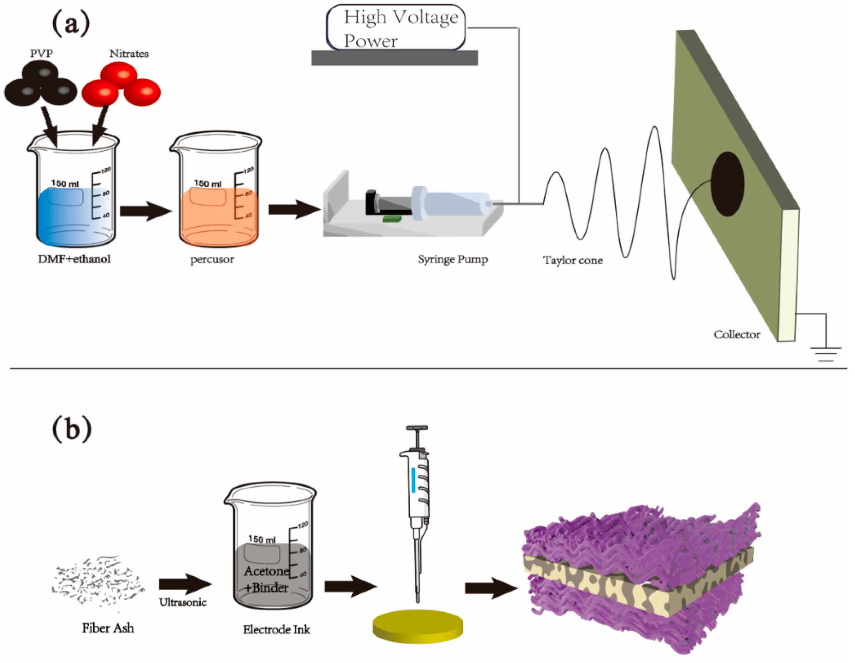
2.1. Material and Cell Preparation

SFMO nanofibers were prepared by the electrospinning technique followed by a calcination procedure. In a typical process for electrospinning, stoichiometric amounts of analytical reagents Sr(NO3)2 (2 mmol), Fe(NO3)3·9H2O (1.5 mmol), and (NH4)6Mo7O24·4H2O (0.07 mmol) were dissolved in a mixture of N,N-dimethylformamide (DMF, 18.3 g) and ethyl alcohol (18.3 g).Then, 8 wt% polyvinylpyrrolidone (PVP, MW = 1,300,000, 3.2 g) was added to the mixture and stirred to form a homogenous precursor solution. The obtained solution was loaded into a 10 mL plastic syringe with a 20-gauge steel nozzle. Figure 1a shows the electrospinning process for fiber fabrication. A syringe pump (LSP01-1A, Ditron-tech, Baoding, China) was used to disperse the solution at an injection flow rate of 6 μL·min−1 with a high-voltage DC power supply maintained at 18.50 kV. A drum collector was fixed to collect the product of the electrospinning process at 100 rpm rotation speed. The distance between the spinneret and the collector was 13 cm. The electrospinning process happens in the space between the tip of the syringe and the collector. Actually, the Taylor cone was a term used to describe the phenomenon of charged droplets being deformed by electrostatic forces to produce a charged cone. Then, the as-prepared fiber film was firstly dried and heated at 200 °C for 1.5 h to remove the polymer and other organic compounds. Finally, the fiber film was sintered at 800 °C for 2 h in air.
The symmetrical cells with the SFMO|LSGM| SFMO configuration were fabricated. Dense LSGM disks were prepared by the uniaxial pressing of commercially available LSGM powders (Terio Corporation, China) followed by subsequent calcination at 1450 °C for 4 h. Figure 1b shows the electrode preparation process for nanofiber-based electrodes. Fiber ash was ultrasonically dispersed for 10 min in a slurry of acetone/binder (α-terpineol and ethylene cellulose) mixture (mass ratio of 5:1) with a solid loading of 5%, and 25 μL of slurry was dripped onto one side of the LSGM electrolyte by a pipette gun. Then, the cell was dried in an oven at 80 °C for 30 min. The drip and dry procedure was repeated three times to form a stable electrode. Additionally, the whole method was carried on the other side of the electrolyte [18,33]. The symmetrical cells were then sintered at 900 °C for 2 h to form electrodes on LSGM with an effective area of 0.5 cm2, at a heating rate of 2 °C·min−1.

2.2. Measurement

The crystal structure of the as-synthesized samples was measured by X-ray diffraction (XRD, Bruker AXS D8 Advance diffractometry, Billerica, USA) with filtered Cu Kα radiation. SFMO Fiber ash and LSGM powder were thoroughly mixed and pressed into a 20.3 × 3.8 × 5.24 mm3 bar and sintered in air at 1300 °C for 6 h. The chemical compatibility of SFMO and LSGM was also tested through X-ray diffraction to examine the existence of the impurity phase.
The electrochemical impedance spectroscopy (EIS) and current-voltage curve (IV) were carried by the German Zahner IM6e electrochemical workstation in the frequency range of 0.1 Hz–1 MHz under 5 mV AC amplitude from 800 °C to 700 °C. The obtained impedance spectrum curve was analyzed by running the DRTtools [34] with MATLAB and fitted on the origin. The symmetrical cell was measured with a different atmosphere in the high-temperature tube furnace. The atmosphere is humidified air with 100 mL·min−1 flow rate or humidified H2 with 60 mL·min−1 flow rate. The single cell was tested under humidified hydrogen and dry air atmospheres. To analyze the microstructures of the nanofiber and symmetrical cells, a scanning electron microscopy (SEM; JSM-IT500HR, Tokyo, Japan) operating at 20 kV was carried out.

3. Results and Discussions

The influence of the calcination temperature in the microstructure of calcined fibers manufactured by electrospinning has been analyzed. Figure 2 shows the SFMO nanofiber’s microstructure image after exposure to different sintering temperatures of 600 °C, 800 °C, and 1000 °C. The calibration notes from Figure 2b,d,f demonstrate that the average diameters of SFMO nanofibers sintered in 600 °C, 800 °C, and 1000 °C are about 110 nm, 100 nm, and 145 nm. When the calcination treatment temperature is 600 °C, the SFMO fiber’s diameter and arrangement are irregular, and there are some clumps of organic polymer remaining on the fibers. When the calcination treatment temperature is 1000 °C, the diameter of SFMO fiber is larger; the calcined fiber is partially adhered and partially broken; and the surface is rough, showing an oversintered character. When the calcination treatment temperature is 800 °C, SFMO reflects an ideal ceramic nanofiber’s structure, including uniform particles, and a large length-to-diameter ratio. The highly porous structure and continuous pathways of the SFMO nanomaterials are confirmed by the SEM image, which shows that all of the prepared SFMO fibers have a 3D interconnected network composed of nanoparticles. As reported in the experimental section, the precursor solutions contained a low amount of polymer, resulting in a reduction in fiber diameters after the heat treatment. Therefore, the nanofibers manufactured with a lower temperature have a wider diameter and a more irregular network, owing to some residual organic components. However, for the temperature of 1000 °C, the majority of the fibers become fragile and broken, which is unfavorable for SOC applications. Thus, the sample calcinated at 800 °C, with an average fiber diameter of 100 nm and clear crystalline fringes, has the beneficial characteristics needed to promote the electrode architectures and prolong the crucial TPB length.
Before testing a symmetrical cell and carrying electrochemical characterization, the chemical compatibility between SFMO and LSGM needs to be verified. Figure 3 shows the XRD patterns of the prepared SFM nanofibers, the LSGM powder, and the SFMO–LSGM mixed bar after sintering at 1300 °C for 6 h, respectively. Firstly, it can be seen that the nanofibers display a clearly defined perovskite structure with a symmetrical cubic phase, which is found to crystallize in the cubic space group Fm3m. Then, the compatibility testing result shows a combination of the characteristic peaks of SFMO and LSGM, and no other phase or shift can be observed, indicating that there is no interaction between the two materials. The lattice parameter of the SFMO nanofiber is 7.8717 Å.
Figure 4 shows cross-sectional images of the symmetrical cell composed of SFMO/LSGM/SFMO. It can be seen from the Figure 4a,b that the fibrous structure has good contact with the dense electrolyte. In Figure 4c,d, the prepared nanofiber-based electrode, composed of many conjoint SFMO nanofiber rods, has an enlarged specific surface area and plenty of pores. The vulnerability of ceramic nanofiber materials may account for the conversion from long fibers to relative short rods, and the average length-to-diameter ratio of the rod-shaped fibers is about 1:4.
The area-specific resistance (ASR) obtained from EIS measurements is an effective parameter for the catalytic performance of the electrode for redox reactions [35]. The EIS of symmetric cells that have an SFMO nanofiber electrode on the LSGM electrolyte was measured with a 4-electrode system in humidified air (3%H2O) and H2 (3%H2O). For comparison, the ohmic resistance (RΩ) was omitted in the Nyquist plots. The difference between the real axis intercepts of the impedance arc is considered to be the polarization resistance (Rp). Figure 5 shows the EIS results of SFMO|LSGM|SFMO symmetrical cell at a temperature range of 700–800 °C and Table 1 recorded the polarization resistance in different working condition. The SFMO nanofiber-based electrodes showed a polarization resistance of 0.14 Ω·cm2 in air and 0.4 Ω·cm2 in H2 at 800 °C. Liu et al. [29] synthesized Sr2Fe1.5Mo0.5O6-δ material through a microwave-assisted combustion method and fabricated a symmetrical cell with a configuration of SFMO|LSGM|SFMO. Its polarization resistances at 800 °C were 0.24 Ω·cm2 in air and 0.27 Ω·cm2 in wet hydrogen. In contrast with their results, the nanofiber-based SFMO electrode had optimal performance in air resulting from the fibrous microstructure through the electrospinning technique.
In an air atmosphere, the polarization resistances increased to 0.24, 0.45 Ω·cm2 for 750 °C, 700 °C. The plot of 700 °C in Figure 5a is similar to a single arc, which at high frequency turns into a straight line with 60° slope with respect to the real axis. This is usually referred to as Gerischer behavior [36]. With the increase in temperature, this single arc shrinks and becomes deformed, with the high-frequency line becoming remarkably narrower in range and reduced in slope, resulting in overall arc depression. Moreover, the low-frequency arc appears gradually after the whole arc shrined, which represents the physical process of gas-phase diffusion. In an H2(3%H2O) atmosphere, the polarization resistances increased to 0.7, 1.4 Ω·cm2 for 750, 700 °C.
When transforming the EIS results into DRT spectra, internal oxygen transport process can be clearly distinguished according to different characteristic DRT peaks [37,38]. Figure 6 illustrates the DRT analysis plots related to SFMO|LSGM|SFMO symmetrical cells in both an oxidizing and a reducing atmosphere at different temperatures. The observed peaks in the G(τ) vs. ln(τ) plot demonstrate that the specific electrochemical processes in which G(τ) is the distribution function of the relaxation time and τ is the relaxation time. Therefore, the area enclosed by a DRT peak stands for polarization resistance corresponding to different electrode process. According to the literature [38,39,40,41], several typical peaks at the DRT spectra can be identified: electronic resistance losses between the working electrode and the current collector; interfacial losses that are independent of the electrode microstructure; chemical losses that are highly dependent on the cathode microstructure, including oxygen surface-diffusion and bulk diffusion; and gas diffusion losses, which are dependent on gas partial pressures [42].
As can be seen from Figure 6a, at 800 °C, there are two major characteristic peaks as P1-P2 for SFMO electrodes in air from relatively high-frequency regions, and two minor peaks as P3-P4 in low-frequency regions, respectively. When the temperature was reduced, three characteristic peaks kept still while the P2 peak rose sharply at the middle-frequency regions. P2 increases with decreasing temperature, which is the rate-controlling process related to the interfacial resistances and is independent of the electrode microstructure. Moreover, the P1, P3, and P4 peaks are associated with charge-transfer resistance, and gas-surface and bulk-diffusion resistances, which are not strongly dependent on temperature. It is noted that a characteristic peak (P5) that does not appear at other temperatures appeared at the right side of the Figure 7a at 750 °C; since its value is small and in the low-frequency region, it mainly reflects the impedance of the mass transfer process and does not account for the main part of the impedance. Therefore, the effect on its particularity can be ignored. The minor changes of P1, P3, and P4 indicate that the nanofiber-based SFMO electrodes have good activity in the hydrogen/air-gas diffusion, adsorption, and dissociation process, and the charge transport and activation reaction of three-phase boundaries [43]. Furthermore, much effort should be made to distinguish their specific relationship in the oxidizing atmosphere. As for the results in the reducing atmosphere, Figure 6b shows the DRT plots transformed from the EIS results in the 3%H2O-H2 atmosphere. Compared with Figure 6a, the rate-controlling process in reducing the atmosphere focuses on the relatively low-frequency area, which correspond to gas diffusion inside the electrodes and surface. With the increase in temperature, all of the peaks shift to the higher-frequency regions and shrink to smaller scales, which ensures that the relaxation of the electrochemical process becomes faster and the corresponding polarization resistance decreases. Specifically, the integral area of the peak represents the resistance of the process. As shown in Figure 6c,d, resistances of different characteristic peaks are calculated. Above all, the analysis from Figure 6 demonstrates that the nanofiber-based SFMO electrodes have proper electrochemical performance and the direction of optimization is to improve the interfacial bonding between the electrolyte and the electrode.
The corresponding electrochemical impedance spectra of LSGM that supported the SOCs with nanofiber-based SFMO symmetrical electrodes under OCVs condition are shown in Figure 7a. The polarization resistance (Rp) values increase from 0.42 to 1.14 Ω·cm2, with the temperature reduced from 800 °C to 700 °C, while the ohmic resistance (RΩ) increases from 0.56 to 1.10 Ω·cm2, suggesting that Rp and RΩ have a similar effect on the electrochemical performance within the operating temperature range. To further verify the electrochemical performance for the nanofiber-based SFMO electrode, the discharge performance of the SOCs was investigated. Figure 7b displays the I−V and I−P curves at 700−800 °C. The cells with the SFMO symmetrical electrode demonstrated peak power densities of 257, 165, and 98 mW·cm−2 at 800, 750, and 700 °C, respectively. Finally, Figure 7c shows the stability of LSGM supported SOCs with nanofiber-based SFMO symmetrical electrode with a discharge current density of 134 mA·cm−2 at 700 °C. The recorded output voltage was given as a function of the operation time and remained relatively stable at 0.63 V for 90 h. These results indicate that nanofiber-based SFMO electrode has practical electrochemical properties for SOCs operating conditions. Additionally, we can further improve the conductivity and electro-catalytic activity of the SFMO electrode by infiltrating other materials and optimizing the microstructure.

4. Conclusions

SFMO nanofibers with a perovskite structure have been successfully fabricated by electrospinning and used for SOC electrodes. The characterization analysis indicated that the nanofiber architecture is a highly porous network with a uniform diameter of about 100 nm and a small grain size. The TPB’s length and reaction rates in electrodes are promoted due to continuous pathways for charge transport and higher permeability for gas penetration by the nanofiber work. The total ASR of the symmetrical cell at 800 °C was 0.14 Ω·cm2 and 0.4 Ω·cm2 in an air and H2 atmosphere, respectively. Additionally, the cell with the same configuration working on the SOFC operation mode exhibited a power density of 257 MW·cm−2, an Rp of 0.42 Ω·cm2, and a durability of 90 h under humidified hydrogen–dry air atmosphere. The impedance spectrum was further investigated via the distribution function of relaxation time, and several characteristic peaks shifted to the left at high frequency with the growth of the temperature. The specific polarization resistances calculated by integral area reveal directions to optimize. Overall, this work provide a basis for the application of electrospinning in the field of energy and the optimization of high-quality electrode materials for SOCs.

Author Contributions

Conceptualization, J.Z. and B.Z.; methodology, B.Z.; validation, H.B.; investigation, B.Z.; resources, Z.L.; data curation, B.Z.; writing—original draft preparation, B.Z.; writing—review and editing, J.Z.; supervision, Y.L.; project administration, S.L.; funding acquisition, J.Z. and S.W. All authors have read and agreed to the published version of the manuscript.

Funding

This research was funded by the National Natural Science Foundation of China (22005146), (U2005215), and (51906109). This work was supported by the Ministry of Science and Technology of China (No. 2021YFE0100200) and the Pakistan Science Foundation (PSF) Project (No. PSF/CRP/18thProtocol (01)). This work was also supported by the Ministry of Science and Technology of Jiangsu Province (No. BK20220011).

Acknowledgments

The authors would like to thank the National Natural Science Foundation of China (22005146), (U2005215), and (51906109). This work was supported by the Ministry of Science and Technology of China (No. 2021YFE0100200) and the Pakistan Science Foundation (PSF) Project (No. PSF/CRP/18thProtocol (01)). This work was also supported by the Ministry of Science and Technology of Jiangsu Province (No. BK20220011).

Conflicts of Interest

The authors declare no conflict of interest.

References

  1. Isenberg, A.O. Energy conversion via solid oxide electrolyte electrochemical cells at high temperatures. Solid State Ion. 1981, 3–4, 431–437. [Google Scholar] [CrossRef]
  2. Ni, M.; Leung, M.K.H.; Leung, D.Y.C. A modeling study on concentration overpotentials of a reversible solid oxide fuel cell. J. Power Sources 2006, 163, 460–466. [Google Scholar] [CrossRef]
  3. Ruiz-Morales, J.C.; Marrero-López, D.; Canales-Vázquez, J.; Irvine, J.T.S. Symmetric and reversible solid oxide fuel cells. RSC Adv. 2011, 1, 1403–1414. [Google Scholar] [CrossRef]
  4. Zhang, Y.; Han, M.; Sun, Z. High performance and stability of nanocomposite oxygen electrode for solid oxide cells. Int. J. Hydrogen Energy 2020, 45, 5554–5564. [Google Scholar] [CrossRef]
  5. Liu, C.; Pu, J.; Chen, X.; Ma, Z.; Ding, X.; Zhou, J.; Wang, S. Influence of anode’s microstructure on electrochemical performance of solid oxide direct carbon fuel cells. Int. J. Hydrogen Energy 2020, 45, 11784–11790. [Google Scholar] [CrossRef]
  6. Zhang, Y.; Xia, C.; Ni, M. Simulation of sintering kinetics and microstructure evolution of composite solid oxide fuel cells electrodes. Int. J. Hydrogen Energy 2012, 37, 3392–3402. [Google Scholar] [CrossRef] [Green Version]
  7. Kenney, B.; Valdmanis, M.; Baker, C.; Pharoah, J.G.; Karan, K. Computation of TPB length, surface area and pore size from numerical reconstruction of composite solid oxide fuel cell electrodes. J. Power Sources 2009, 189, 1051–1059. [Google Scholar] [CrossRef]
  8. Chen, D.; Lin, Z.; Zhu, H.; Kee, R.J. Percolation theory to predict effective properties of solid oxide fuel-cell composite electrodes. J. Power Sources 2009, 191, 240–252. [Google Scholar] [CrossRef]
  9. Yang, L.; Li, Y.; Hou, Z.; Shi, C.; Zhang, G.; Zeng, F.; Zhou, J.; Wang, S. La1-xCaxFeO3-δ air electrode fabricated by glycine-nitrate combustion method for solid oxide electrolysis cell. Ceram. Int. 2021, 47, 32318–32323. [Google Scholar] [CrossRef]
  10. Li, Y.; Yang, L.; Li, W.; Hou, Z.; Shi, C.; Zhang, G.; Zhou, J.; Wang, S. A promising strontium and cobalt-free air electrode Pr1-xCaxFeO3-δ for solid oxide electrolysis cell. Int. J. Hydrogen Energy 2021, 46, 30230–30238. [Google Scholar] [CrossRef]
  11. Zhang, W.; Zhou, Y.; Hussain, A.M.; Song, D.; Miura, Y.; Chen, Y.; Luo, Z.; Kane, N.; Niu, Y.; Dale, N.; et al. High-Performance, Thermal Cycling Stable, Coking-Tolerant Solid Oxide Fuel Cells with Nanostructured Electrodes. ACS Appl. Mater. Interfaces 2021, 13, 4993–4999. [Google Scholar] [CrossRef] [PubMed]
  12. Ren, R.; Wang, Z.; Meng, X.; Xu, C.; Qiao, J.; Sun, W.; Sun, K. Boosting the Electrochemical Performance of Fe-Based Layered Double Perovskite Cathodes by Zn2+ Doping for Solid Oxide Fuel Cells. ACS Appl. Mater. Interfaces 2020, 12, 23959–23967. [Google Scholar] [CrossRef] [PubMed]
  13. Ma, Z.; Li, Y.; Zheng, Y.; Li, W.; Chen, X.; Sun, X.; Chen, X.; Zhou, J. La0.75Sr0.25Cr0.5Mn0.5O3- as cathode for electrolysis and co-electrolysis of CO2 and H2O in solid oxide electrolysis cell. Ceram. Int. 2021, 47, 23350–23361. [Google Scholar] [CrossRef]
  14. Ahn, M.; Cho, J.; Lee, W. One-step fabrication of composite nanofibers for solid oxide fuel cell electrodes. J. Power Sources 2019, 434, 226749. [Google Scholar] [CrossRef]
  15. Parbey, J.; Wang, Q.; Yu, G.; Zhang, X.; Li, T.; Andersson, M. Progress in the use of electrospun nanofiber electrodes for solid oxide fuel cells: A review. Rev. Chem. Eng. 2020, 36, 879–931. [Google Scholar] [CrossRef]
  16. Enrico, A.; Zhang, W.; Lund Traulsen, M.; Sala, E.M.; Costamagna, P.; Holtappels, P. La0.6Sr0.4Co0.2Fe0.8O3-δ nanofiber cathode for intermediate-temperature solid oxide fuel cells by water-based sol-gel electrospinning: Synthesis and electrochemical behaviour. J. Eur. Ceram. Soc. 2018, 38, 2677–2686. [Google Scholar] [CrossRef] [Green Version]
  17. Hieu, N.T.; Park, J.; Tae, B. Synthesis and characterization of nanofiber-structured Ba0.5Sr0.5Co0.8Fe0.2O3-δ perovskite oxide used as a cathode material for low-temperature solid oxide fuel cells. Mater. Sci. Eng. B 2012, 177, 205–209. [Google Scholar] [CrossRef]
  18. Chen, Y.; Bu, Y.; Zhang, Y.; Yan, R.; Ding, D.; Zhao, B.; Yoo, S.; Dang, D.; Hu, R.; Yang, C.; et al. A Highly Efficient and Robust Nanofiber Cathode for Solid Oxide Fuel Cells. Adv. Energy Mater. 2016, 7, 1601890. [Google Scholar] [CrossRef]
  19. Zhang, W.; Wang, H.; Guan, K.; Wei, Z.; Zhang, X.; Meng, J.; Liu, X.; Meng, J. La0.6Sr0.4Co0.2Fe0.8O3-delta/CeO2 Heterostructured Composite Nanofibers as a Highly Active and Robust Cathode Catalyst for Solid Oxide Fuel Cells. ACS Appl. Mater. Interfaces 2019, 11, 26830–26841. [Google Scholar] [CrossRef]
  20. Guo, Y.; Guo, T.; Zhou, S.; Wu, Y.; Chen, H.; Ou, X.; Ling, Y. Characterization of Sr2Fe1.5Mo0.5O6-delta-Gd0.1Ce0.9O1.95 symmetrical electrode for reversible solid oxide cells. Ceram. Int. 2019, 45, 10969–10975. [Google Scholar] [CrossRef]
  21. Rath, M.K.; Lee, K.-T. Superior electrochemical performance of non-precious Co-Ni-Mo alloy catalyst-impregnated Sr2FeMoO6-delta as an electrode material for symmetric solid oxide fuel cells. Electrochim. Acta 2016, 212, 678–685. [Google Scholar] [CrossRef]
  22. Han, Z.; Dong, H.; Wu, Y.; Yang, Y. Locating the rate-limiting step of hydrogen conversion on Sr2Fe1.5Mo0.5O6 (0 0 1) surface: Implications for efficient SOFC anode design. Appl. Surf. Sci. 2022, 595, 153513. [Google Scholar] [CrossRef]
  23. Muñoz-García, A.B.; Pavone, M.; Carter, E.A. Effect of Antisite Defects on the Formation of Oxygen Vacancies in Sr2FeMoO6: Implications for Ion and Electron Transport. Chem. Mater. 2011, 23, 4525–4536. [Google Scholar] [CrossRef]
  24. Li, H.; Zhao, Y.; Wang, Y.; Li, Y. Sr2Fe2−Mo O6—Perovskite as an anode in a solid oxide fuel cell: Effect of the substitution ratio. Catal. Today 2016, 259, 417–422. [Google Scholar] [CrossRef] [Green Version]
  25. Zhang, S.; Pu, X.; Wan, Y.; Zhu, K.; Xia, C. Research progress in effect of element doping on electrochemical properties of Sr_2Fe_(1.5)Mo_(0.5)O_(6-delta) based anode materials. J. Mater. Eng. 2021, 49, 1–13. [Google Scholar]
  26. Porotnikova, N.M.; Osinkin, D.A. Recent advances in heteroatom substitution Sr2Fe1.5Mo0.5O6-δ oxide as a more promising electrode material for symmetrical solid-state electrochemical devices: A review. Electrochem. Mater. Technol. 2022, 1, 20221003. [Google Scholar]
  27. Li, M.; Ni, M.; Su, F.; Xia, C. Proton conducting intermediate-temperature solid oxide fuel cells using new perovskite type cathodes. J. Power Sources 2014, 260, 197–204. [Google Scholar] [CrossRef]
  28. Tian, C.; Cheng, J.; Yang, J. A highly active cathode material of Cu-doped Sr2Fe1.5Mo0.5O6 for symmetrical solid oxide fuel cells. J. Mater. Sci.-Mater. Electron. 2021, 32, 1258–1264. [Google Scholar] [CrossRef]
  29. Qiu, P.; Sun, S.; Li, J.; Jia, L. A review on the application of Sr2Fe1.5Mo0.5O6-based oxides in solid oxide electrochemical cells. Sep. Purif. Technol. 2022, 298, 121581. [Google Scholar] [CrossRef]
  30. Liu, Q.; Dong, X.; Xiao, G.; Zhao, F.; Chen, F. A Novel Electrode Material for Symmetrical SOFCs. Adv. Mater. 2010, 22, 5478–5482. [Google Scholar] [CrossRef]
  31. Yang, G.; Feng, J.; Sun, W.; Dai, N.; Hou, M.; Hao, X.; Qiao, J.; Sun, K. The characteristic of strontium-site deficient perovskites SrxFe1.5Mo0.5O6-delta (x = 1.9–2.0) as intermediate-temperature solid oxide fuel cell cathodes. J. Power Sources 2014, 268, 771–777. [Google Scholar] [CrossRef]
  32. Wang, Z.; Tian, Y.; Li, Y. Direct CH4 fuel cell using Sr2FeMoO6 as an anode material. J. Power Sources 2011, 196, 6104–6109. [Google Scholar] [CrossRef]
  33. Parbey, J.; Xu, M.; Lei, J.; Espinoza-Andaluz, M.; Li, T.S.; Andersson, M. Electrospun fabrication of nanofibers as high-performance cathodes of solid oxide fuel cells. Ceram. Int. 2020, 46, 6969–6972. [Google Scholar] [CrossRef]
  34. Wan, T.H.; Saccoccio, M.; Chen, C.; Ciucci, F. Influence of the Discretization Methods on the Distribution of Relaxation Times Deconvolution: Implementing Radial Basis Functions with DRTtools. Electrochim. Acta 2015, 184, 483–499. [Google Scholar] [CrossRef]
  35. Nechache, A.; Mansuy, A.; Petitjean, M.; Mougin, J.; Mauvy, F.; Boukamp, B.A.; Cassir, M.; Ringuedé, A. Diagnosis of a cathode-supported solid oxide electrolysis cell by electrochemical impedance spectroscopy. Electrochim. Acta 2016, 210, 596–605. [Google Scholar] [CrossRef]
  36. Pototskaya, V.V.; Gichan, O.I. The Gerischer finite length impedance: A case of unequal diffusion coefficients. J. Electroanal. Chem. 2019, 852, 113511. [Google Scholar] [CrossRef]
  37. Ivers-Tiffee, E.; Weber, A. Evaluation of electrochemical impedance spectra by the distribution of relaxation times. J. Ceram. Soc. Jpn. 2017, 125, 193–201. [Google Scholar] [CrossRef] [Green Version]
  38. Osinkin, D.A. An approach to the analysis of the impedance spectra of solid oxide fuel cell using the DRT technique. Electrochim. Acta 2021, 372, 137858. [Google Scholar] [CrossRef]
  39. Oz, A.; Gelman, D.; Tsur, Y.; Singh, K.; Thangadurai, V. Evolutionary Programming Based Approach for SOFC Cathode Characterization: A Case Study on Co-Free Mixed Conducting Perovskites. ECS Trans. 2017, 78, 2099–2108. [Google Scholar] [CrossRef]
  40. Jing, C.; Bo, Y.U.; Wen-Qiang, Z.; Xue, W. SOC Stack Impedance Characterization and Identification Based on DRT and ADIS Methods. J. Inorg. Mater. 2016, 31, 1279–1288. [Google Scholar] [CrossRef]
  41. Sumi, H.; Shimada, H.; Yamaguchi, Y.; Mizutani, Y.; Okuyama, Y.; Amezawa, K. Comparison of electrochemical impedance spectra for electrolyte-supported solid oxide fuel cells (SOFCs) and protonic ceramic fuel cells (PCFCs). Sci. Rep. 2021, 11, 10622. [Google Scholar] [CrossRef] [PubMed]
  42. Ji, Y.; Feng, C.; Shao, S.; Li, X.; Huang, X.; Cao, J. An electrochemical assessment of pristine SrCoO3-δ using the distribution of relaxation times analysis. Asia-Pac. J. Chem. Eng. 2022, 17, e2784. [Google Scholar] [CrossRef]
  43. Boukamp, B.A. Derivation of a Distribution Function of Relaxation Times for the (fractal) Finite Length Warburg. Electrochim. Acta 2017, 252, 154–163. [Google Scholar] [CrossRef]
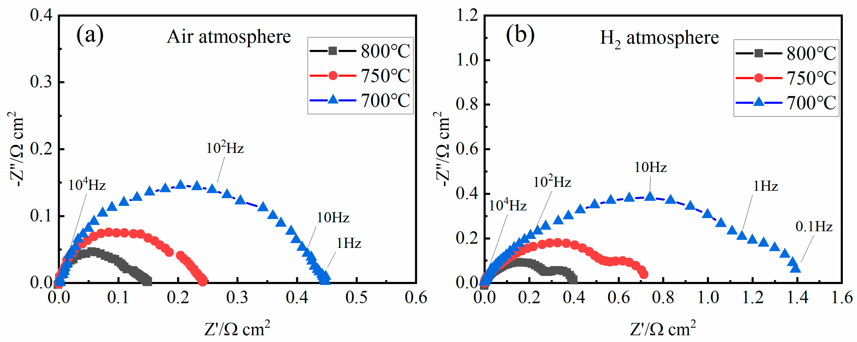
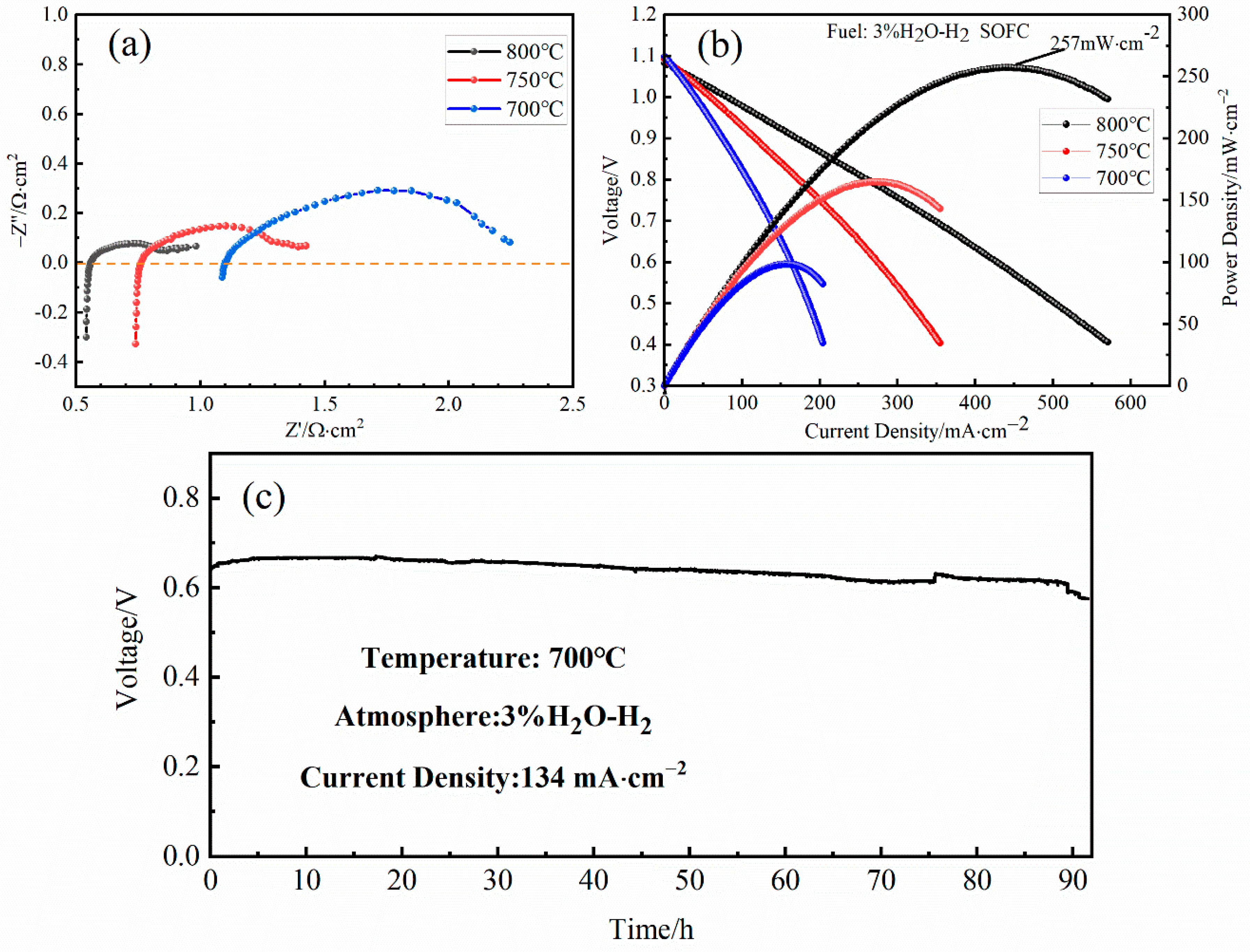
Figure 1. Schematic illustration of the electrospinning process for fiber fabrication (a) and electrode preparation for nanofiber-based electrodes (b).
Crystals 12 01624 g001
Figure 2. SEM images of SFMO fibers after electrospinning and calcination, obtained with different calcination temperatures of (a,b) 600 °C, (c,d) 800 °C, and (e,f) 1000 °C.
Crystals 12 01624 g002
Figure 3. X-ray diffraction patterns of SFMO nanofibers, LSGM powder (commercial), and SFM–LSGM powder mixture after being fired at 1300 °C for 6 h.
Crystals 12 01624 g003
Figure 4. SEM images of SFMO nanofibers on the LSGM electrolyte after cell calcination: (a,b) the interface between the electrode and the electrolyte; (c,d) SFMO electrode.
Crystals 12 01624 g004
Figure 5. Polarization resistance of SFMO nanofiber electrode without ohmic resistance measured at 700, 750, and 800 °C in humidified air (a) and H2 (b).
Crystals 12 01624 g005
Figure 6. DRT analysis results of impedance spectra and simulated resistances corresponding to characteristic peaks from 700 °C to 800 °C, under oxidizing conditions (a,c) and reducing conditions (b,d).
Crystals 12 01624 g006
Figure 7. Impedance spectra under open-circuit conditions (a) and I−V and I−P curves of humidified H2 (b), for LSGM electrolyte-supported SOCs with nanofiber-based SFM symmetrical electrode measured from 800 °C to 700 °C and 90 h duration test in the SOFC working mode (c).
Crystals 12 01624 g007
Table 1. The area-specific resistances for SFMO symmetrical cells.
Resistance (Ω∙cm2)800 °C750 °C700 °C
Rp-H20.40.721.4
Rp-Air0.140.240.45
Publisher’s Note: MDPI stays neutral with regard to jurisdictional claims in published maps and institutional affiliations.

