Article

Microstructure Evolution during Mechanical Alloying of a Biodegradable Magnesium Alloy

1
Department of Metallic Materials Processing and Ecometallurgy, University POLITEHNICA of Bucharest, 060042 Bucharest, Romania
2
Faculty of Mechanical, Industrial and Maritime Engineering, OVIDIUS University of Constanta, 900527 Constanța, Romania
3
Department of Oral Rehabilitation, Faculty of Dental Medicine, Iuliu Hatieganu University of Medicine and Pharmacy, 400349 Cluj-Napoca, Romania
4
Zircon Dent SRL, 400690 Cluj-Napoca, Romania
5
National Institute for Research and Development in Micro-Technologies, 077190 Bucharest, Romania
6
Romanian Academy, Institute of Physical Chemistry “Ilie Murgulescu”, Spl. Independentei 202, 060021 Bucharest, Romania
*
Author to whom correspondence should be addressed.
Crystals 2022, 12(11), 1641; https://doi.org/10.3390/cryst12111641
Submission received: 27 October 2022 / Revised: 10 November 2022 / Accepted: 11 November 2022 / Published: 15 November 2022
(This article belongs to the Special Issue Advances in Magnesium Alloys: Microstructure, Coating, and Machining)

Abstract

:
The aim of the present work was to apply a mechanical alloying method to obtain a Mg-10Zn-0.5Zr-0.8Ca powder-alloy with morphological and dimensional characteristics, proper for subsequent selective laser melting (SLM) processing. The mechanical alloying process was applied at different values of the milling time. Thus, the evolution of the main morphological and dimensional characteristics of the experimented powder-alloy could be studied. The conclusion of this study is that mechanical alloying possesses good potential to obtain powder-alloy with almost rounded morphology and fine dimensions, proper for further additive manufacturing procedures such as selective laser melting.

1. Introduction

Presently, intensive research has developed on biodegradable materials [1,2], especially on magnesium-based materials, mainly due to their mechanical properties that generally are similar to those of human bones [3,4,5]. This is an important characteristic of a biodegradable implant device, to maintain similar loads for the implant and bone as well [6,7]; if the mechanical loads are different, then the bone will have the tendency to adapt and remodel itself to be either stronger, causing the well-known “stress shielding” [8,9], or softer and much more porous, causing osteopenia [10,11]. Mg alloys can fulfil this criterion, to maintain similar loads on the implant and the bone as well. In addition, magnesium has a low density of just 1.74 g/cm3, the closest density to that of natural cortical bone (1.8–2.1 g/cm3). The Young modulus values are also very close: approximately 45 GPa for the Mg alloys and about 7–30 GPa for human natural bone [3,4]. This advantage, combined with special osteoconductive properties of the magnesium, cause it to be appreciated when used as bone implants. Many recent published scientific reports indicate a high interest in the Mg-based alloys used for biodegradable metal scaffolds [5,12] or bone screws [13,14]. For these implant devices, the main problem is the manufacturing of a suitable macro- and microgeometry adapted particularly to the anatomy of the patient [15]. Classical methods can be often inefficient for obtaining a special microstructure with necessary interconnected pores capable of initiating cell ingrowth [16]. To resolve this problem, additive manufacturing (AM) methods are now envisaged and implemented [17]. Even if they are expensive in the moment and are not adapted to manufacturing parts in mass production, these methods become a necessity for an increasingly diversified implantology, and therefore their development is of the utmost relevance and actuality, especially concerning biodegradable Mg alloys.
The AM methods imply metallic powder bed fusion (PBF), with its variant’s electron-beam powder bed fusion (EB-PBF) or, most frequently used, laser-powder bed fusion (L-PBF) with the more recent and adapted name of selective laser melting (SLM) [18,19]. When applying the AM methods for Mg alloys, the main problem is the evaporation of the Mg that affects the propagation of the electron beam in the vacuum [20,21]. Therefore, the SLM method seems to be more adequate [19]. For this, the quality of the metallic powder characteristics is of maximum importance: the chemical composition; dimension; morphology, i.e., a powder as fine as possible; a highly homogeneous microstructure that implies a spherical shape; uniform size; high density; being without pores or various inclusions; and with a homogeneous chemical structure [3,4,5]. To obtain these powder characteristics, the gas atomization method is often used, followed by the mechanical alloying (MA) and water atomization methods. Presently, all three variants are recommended even if there are some existing pro and contra arguments [15,22]. Gas atomization and mechanical alloying could both be more suitable considering that the water atomization method has the disadvantage of an irregularly shaped powder and of a greater oxygen content [23,24,25]. However, the mechanical alloying method is considered and proven to be a more efficient and low-cost method than its gas atomization counterpart in terms of resource consuming (materials and energy) in the whole processing chain [26]. In addition, it must be considered that mechanical alloying can lead to a powder-material with a nanocrystalline or even amorphous structure as a result of the repeated fracturing and cold welding of the component particles, a phenomenon determined by the severe plastic deformation that occurs, even if the morphology the powder obtained is not so regular and spherical as in the case of gas atomization [18,27].
Concerning the chemical composition, a series of experimental tests have been reported for alloying Mg alloys with various chemical elements such as Zn, Zr, Ca, Li, Al, Mn, Sr, or Si, or even some rare earth (RE) elements such as Ce, La, Nd, Pr, Y, Gd, or Sc, that are biocompatible and also can improve the mechanical and corrosive properties of the Mg alloys [3,4,23]. The main problem when alloying Mg is the severe evaporation and high chemical reactivity of the Mg, especially with oxygen [3,4,5]. Several scientific works can be listed that reported results related to biodegradable Mg alloys, with different alloying elements: [28,29] for pure Mg; [30] for the Mg-Zn-Zr-RE alloy, abbreviated as ZEK100; [31] for the ternary alloy Mg-Zn-Zr; [32] for the Mg-RE-Zr alloy, abbreviated as WE; [33] for the Mg-Zn-Ca-Mn, abbreviated as ZX; [34,35] for the Mg-Li-Al-RE alloy, abbreviated as LAE442; [36] for the Mg-Ca alloy; [37] for the Mg-Y-Zr-Ca alloy; [38] for the Mg-Zn-Sr alloy; [39] for the Mg-Zn-Ca-Ce alloy; [40] for the Mg-Zn-Ca alloy; [41] for the Mg-Zn-Ca-Pr alloy; [42] for the Mg-Zn-Zr-Mn alloy; [43] for the Mg-Al alloy; [44,45,46,47,48] for the Mg-Al-Zn alloy, abbreviated as AZ; and [18] for the Mg-Zn-Ca-Gd alloy. All these reports represent preliminary attempts. Of all these tested chemical variants, the alloys with Al have been shown to promote neurodegenerative diseases or even cancer [49], and the alloys containing RE elements have the main disadvantage of being expensive and difficult to access. The most affordable of them seem to be the Mg alloys with Zn, Zr, and Ca, which are biocompatible, inexpensive, and easier to process. It should be mentioned that Zn and Zr are indicated as important alloying elements for Mg bioalloys due to solid-solution strengthening of the Mg that increases the Mg’s corrosion properties [50,51]. The equilibrium limit of Zn solubility in α-Mg is 6.2% wt. at 340 °C [31]. Calcium (Ca), on the other hand, the one of the most important chemical elements in human bone, has a low density (1.55 g/cm3) like Mg, is not expensive, and favours the production of hydroxyapatite in the body accelerated by this the bone healing [52,53]; moreover, Ca is able to control the corrosion rate of Mg alloys [54]. The maximal equilibrium limit of Ca solubility in Mg is 1.11% wt. at 521 °C.
Concerning the method of preparation of the Mg alloy in its powder state by mechanical alloying, poor information is available thus far on Mg alloys with all three of Zn, Ca, and Zr.
Thus, the present paper represents a preliminary study and experiments concerning the influence of milling time on the microstructural characteristics of the Mg-based biodegradable alloy Mg-10Zn-0.8Ca-0.5Zr (% wt.) prepared by mechanical alloying. This chemical composition has not been tested before by another research group. The final goal is to obtain a powder with as many adequate microstructural characteristics as possible—powder dimensions, morphology, and chemical composition—suitable for further additive manufacturing processing, such as the SLM method, for example. For the study of the above objective, X-ray diffraction (XRD), scanning electron microscopy (SEM), and energy-dispersive spectroscopy (EDS) were carried out on mechanical alloy powder. A preliminary SLM processing was also tested.

2. Materials and Methods

2.1. The Obtaining of the Mg-Zn-Ca-Zr Alloy Powder by a Mechanical Alloying Procedure

A mixture of elemental powders of Mg (99.00% purity, <100 μm), Zn (99.00% purity, <40–50 μm), Zr (99.00% purity, <40–50 μm), and granules of Ca was processed by a mechanical alloying procedure with various milling times, from 2 to 10 h. The selected chemical composition of the Mg alloy to be obtained in powder state is: Mg-10Zn-0.8Ca-0.5Zr (% wt.). The applied experimental procedures are shown in Figure 1.
The amount of Zn is higher than the maximum solubility of Zn in Mg; in already reported papers [31,32,33,38,39,40,41,42], the Zn content does not usually exceed the amount of 6% wt. Here, a higher amount was selected, of 10% wt., since Zn, even if it exceeds the limit of maximum solubility of 6.2% wt., could enter in solid solution entirely due to severe plastic deformation that occurs during the mechanical alloying procedure and, by that, it could facilitate a superior strength and a grain refining process. On the other hand, zirconium (Zr) acts also as a grain refiner for Mg alloys. If the Zr content is higher than 0.5% wt., there is a risk for activating anodic reactions, accelerating by this the general corrosion of the alloy [55,56,57]. Therefore, for the present case the amount of Zr was limited to 0.5% wt. Concerning calcium, previous studies [58,59] have indicated that, for the multicomponent Mg alloys, an improved corrosion resistance can be achieved with a Ca amount under ≤1% wt.; therefore, here it was established as 0.8% wt.
The mechanical alloying procedure consisted of milling the powder mixture using a high-energy PM 100 Retsch planetary mill (500 mL capacity/50/60 Hz frequency/10 mm diameter of zirconium oxide balls); the used protective atmosphere was argon of 1.5 bar overpressure; moreover, to prevent excessive cold welding of the powders during milling process, 5% n-heptane solution was added. For a good performance of the milling process, a powder to zirconium oxide ball weight ratio of 10:1 was applied, which is a frequent ratio used for this process. The applied milling speed is usually between 150–350 rpm; here, the applied milling speed was 300 rpm. The milling time was the variable parameter, with following applied values: 2 h, 4 h, 6 h, 8 h, and 10 h. The intension was to observe step by step the evolution of the powder microstructure, consistency, and homogeneity during the mechanical alloying procedure. The sieving process after the MA procedure has been made using the following subsequent dimensions: (a) 100–60 µm; (b) 60–30 µm; and (c) <30 µm.

2.2. The Processing of the Mg-Zn-Ca-Zr Alloy Powder by a Selective Laser Melting (SLM) Procedure

Given that the obtained powder-alloy is assigned for the following 3D printing processing, at the end of the mechanical alloying procedure, the finer obtained powder was selected to be processed by SLM method for a preliminary test.
The powder-alloy with the maximum tested milling time value of 10 h was selected to be processed for an SLM trial. The type of laser used was MYSINT 100- 3D Selective Laser Fusion, a special printer for metal powder, with a power supply of 220–240 V, 50/60 Hz; the maximum power absorbed was 1.53 kW; the used inert gases were nitrogen and argon. The applied laser parameters were: laser power—50–200 W; laser speed—600–1000 mm/s; layer height—20–30 µm; and laser energy density—160–560 J/mm3.

2.3. The Microstructural and Mechanical Analysis of the Mg-Zn-Ca-Zr Alloy

The microstructural analysis of the studied alloy included the following stages: (a) a scanning electron microscopy with energy-dispersive spectroscopy (SEM-EDS) for imaging investigations and calculations of powder characteristics (dimension, morphology, and homogeneity) for the Mg-Zn-Ca-Zr alloy in SLM condition, performed on a Tescan VEGA II-XMU SEM microscope equipped with a Bruker QUANTAX xFlash 6/30 EDS detector. The particles size of the obtained powder-alloy was measured with the same SEM-calibrated microscope of the Tescan VEGA II-XMU type; (b) a powder X-ray diffraction (XRD) analysis performed for the Mg-Zn-Ca-Zr powder-alloy at room temperature using a RIGAKU MiniFlex600 (RIGAKU, Tokyo, Japan) benchtop diffractometer with Cu-Kα radiation and a scattering angle of 2θ in the range of 30–90 degrees for a step size of 0.02 degrees, providing a detection limit in the range of 0.1 to 1% wt. The whole powder pattern fitting (WPPF), including the Rietveld method [60], was used. For the Profile Shape Function, a pseudo-Voigt function (a linear combination—the weighted sum of Gauss and Lorentz functions) was used, preferred when microstrain broadening dominated. The WPPF analysis helped to identify the present phases, the space groups, the refinement of unit-cell parameters, and the crystallite sizes and lattice microstrains.
Samples of the Mg-Zn-Ca-Zr alloy in SLM condition were mechanically tested for compression. A universal INSTRON 3382 material testing machine (Instron Ltd., High Wycombe, Buckinghamshire, HP123SY, UK) was used for this test. The necessary load was applied increasingly until the sample broke. The corresponding strain-stress curves were obtained and analysed.

3. Results and Discussions

3.1. Microstructure Characterisation and Evolution

The microstructure characterization and evolution during mechanical alloying applied at 2 h, 4 h, 6 h, 8 h, and 10 h milling time was carried out with the help of XRD analysis and SEM imaging with completion by EDS analysis.
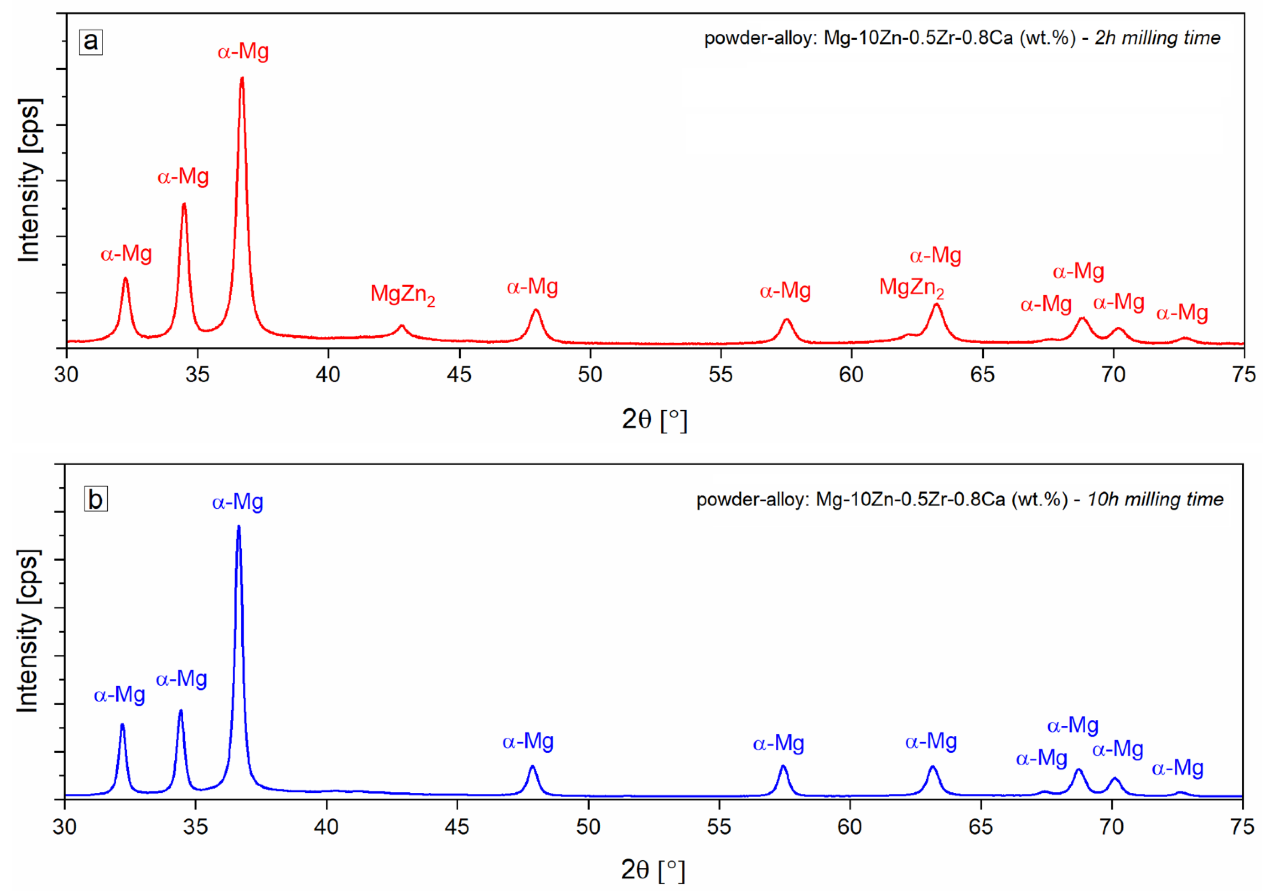
Figure 2a represents the XRD patterns for the powder-alloy sample with the shorter milling time (2 h-top image) and the Figure 2b for the longest milling time (10 h-bottom image). The top image presents visible sharp peaks of XRD patterns corresponding mainly to the α-Mg phase, and also to MgZn2, as a secondary phase, with only a few and very weak peaks; the bottom image presents visible peaks for the α-Mg phase as the only identified phase. The Mg-based solid solution is identified as being of space group P63/mmc, with a hexagonal crystallographic system with cell parameters a = 0.32062 nm and c = 0.52028 nm. The fact that the bottom image indicates the presence of only the α-Mg phase, suggests that all alloying chemical elements—Zn, Zr, and Ca—enter gradually in the Mg-based solid solution with increasing milling times. The powder material obtained after the longest milling time will be tested for the subsequent SLM procedure to verify if the alloy in powder form can be a suitable feed-stock material for this kind of process.
Between all three alloying elements, only a Zn content of 10% wt. exceeded the maximum solubility in Mg (6.2% wt.); for such a chemical content, the MgZn2 phase should have formed in the case of a classical synthesis of the alloy (melting-solidification). MgZn2 is a thermally and mechanically stable phase, and can have in some cases a beneficial influence, as reported, due to its character of strengthening and stabilization [61]. However, in the case of the presently provided mechanical alloying process, due to the continuous severe plastic deformations of the powder particles, interposed with cold welds and successive and constant fractures, a large amount of energy was generated capable of achieving a homogeneous distribution of the chemical elements in the Mg powder particles, mostly conducing to a homogeneous microstructure with similar proportions to the starting powders. This microstructure possibility was also reported by [27]. Even more, it is reported that for a much longer milling time, about 70 h in the case of [18], an amorphous structure is possible to be achieved.
The result highlighted by the XRD analysis in Figure 2b will also be demonstrated by the EDS analysis presented and discussed in the continuation of this work. As a possible observation, it can be understood that the homogeneous distribution of the alloying elements in the samples, assumed by the XRD analysis, cannot guarantee the 100% absence of MgZn2.
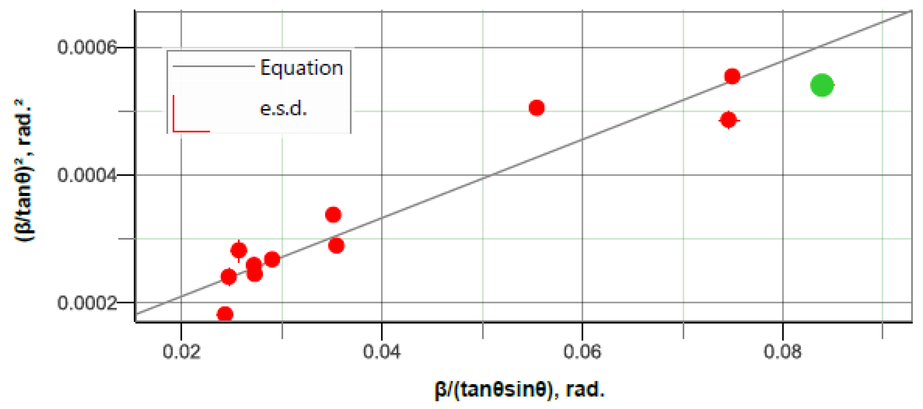
Between other factors which may contribute to the observed peak profile, crystallite size and lattice microstrain are of interest. Thus, the refinement of unit-cell parameters, the crystallite size, and lattice strain were determined; the average value for crystallite size was 247 Å and the average value was 0.236% for lattice microstrain. Figure 2, Figure 3 and Figure 4 prove the positive correlation for the measured data concerning the refinement of unit-cell parameters (Figure 3), the crystallite size, and the lattice strain (Figure 4). The peak list is presented in Table 1.
The alloying chemical elements—Zn, Zr, and Ca—in the Mg-based solid solution, as well as possible local variation in the composition, can create a distribution of d-spacing for a crystallographic plane (which is observed as a broad peak). The lattice micro-strain, ε = Δd/d, is an upper limit of lattice distortion caused by nonuniform distortions in the crystal as a consequence of deviations from ideal crystalline lattice (perfectly ordered crystalline array). In the studied case it was presumed to be produced by residual stresses, dislocations, and any other defect that causes a nonuniform lattice distortion in the crystal.
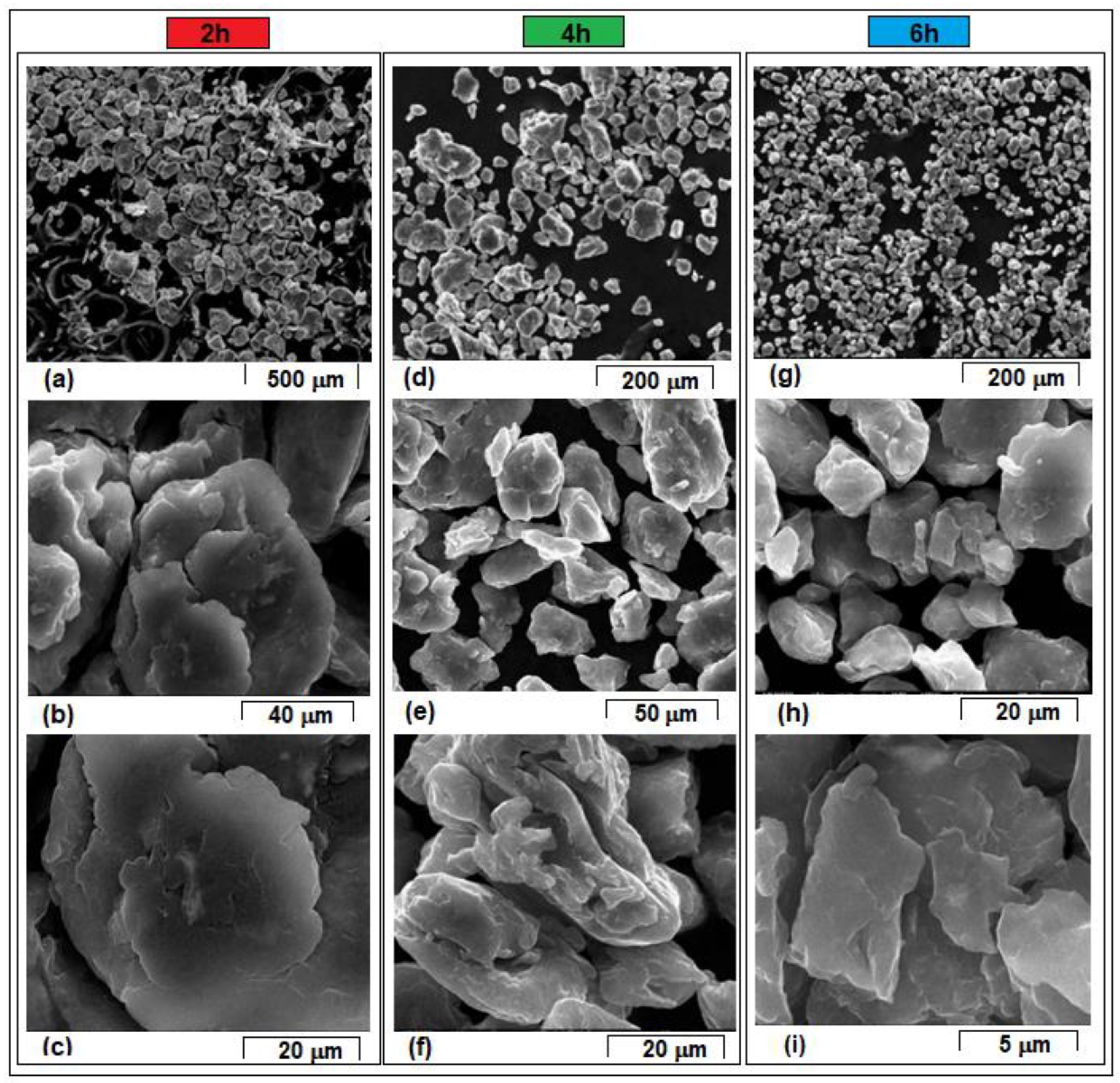
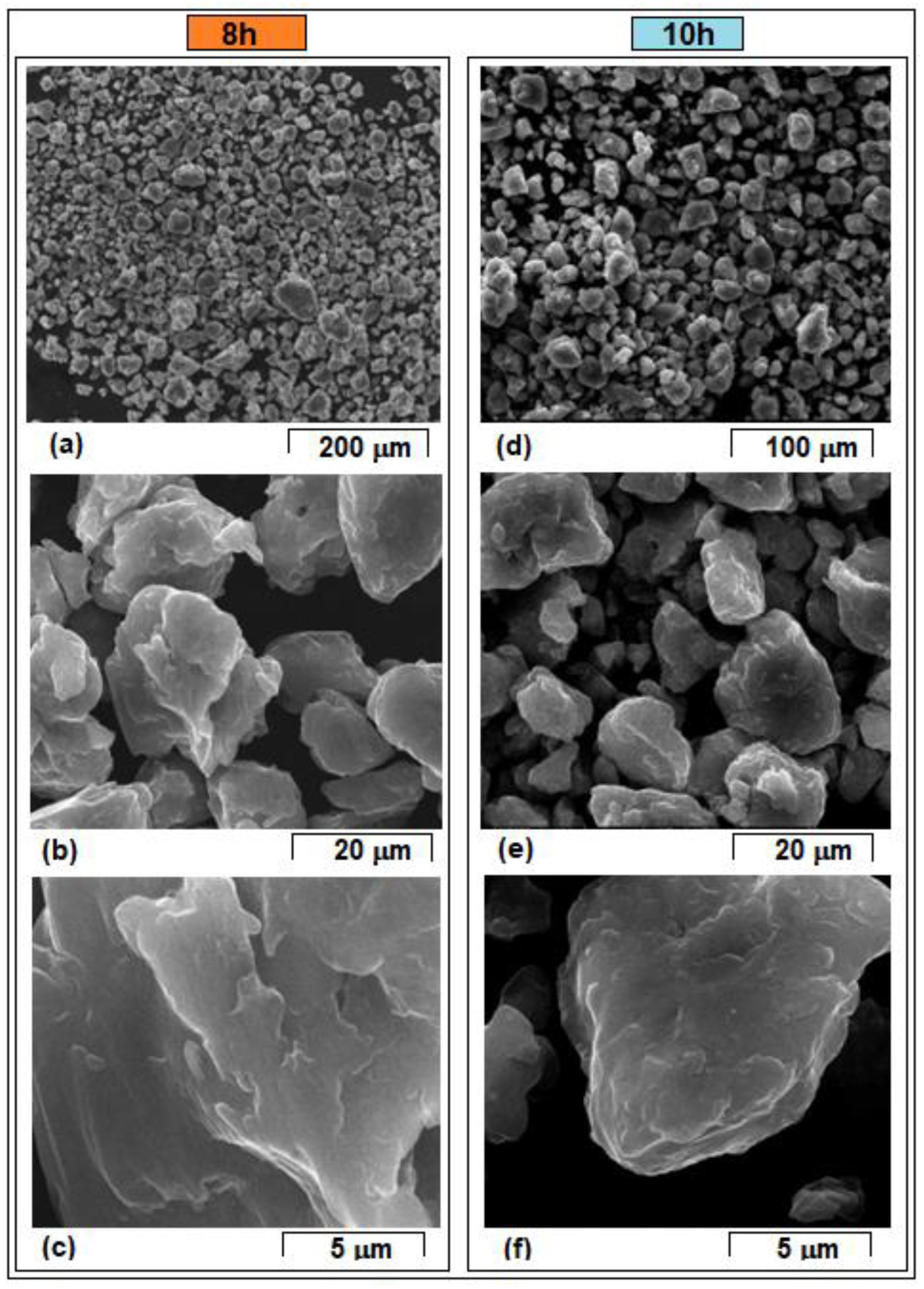
The SEM micrographs of the powder samples from Figure 5 and Figure 6 show the powder structure, morphology, and dimension evolution, along with the milling time.
The images are ordered according to the achieved magnification, in ascending order. The images corresponding to the samples obtained for milling times 2 h, 4 h, and 6 h, respectively, are grouped in Figure 5. In Figure 6, those for 8 h and 10 h are grouped.
As a general observation, it can be noted that the size of the powders obtained by mechanical alloying decreases with the increase of milling times, more drastically for the first three variants of time (74.6 µm → 24.7 µm → 16.6 µm), and with a sort of stabilization for the next two experimental variants (18.9 µm → 16.2 µm). However, the dimensional homogeneity of each variant itself increases with the increase of these times: for the first two variants (2 h and 4 h), powders with quite variable sizes are observed; this is a variety which, however, homogenizes for the last three variants of times (6 h, 8 h, and 10 h). At higher magnifications, it is observed that the surface of the powder particles becomes more and more homogeneous: in the first variants, glued particles are observed (Figure 5b,c,f, for example); later they become individualized and morphologically homogeneous, with smoother external shapes and closer to a rounded outline (Figure 6c,f).
From the perspective of the size of the powders obtained by MA, Figure 7, based on Table 2, shows the direct measurements of particle size using SEM-calibrated microscopy images, as well as the average values together with the corresponding standard deviations.
Generally, few stages are reported for the microstructural and morphological evolutions of the powder mixture during the mechanical alloying process [18]. For the present case, it can be noted that compared to the initial sizes of the powders corresponding to the pure elements (<100 µm for Mg and <40–50 µm for Zn, Zr, and Ca), after 2 h of milling, the sizes of the obtained powders corresponded to an average of the initial values (74.6 µm). The corresponding SEM images from Figure 5a–c show agglutinated particles of different sizes due to the merging process between the particles, which can be considered as first stage of the initial formation of the powder microstructure and morphology; it can also be observed that few and very small insolubilized elements (of lighter colour) became stuck into the larger particles (Figure 5c).
After 4 h of milling, the size of the powder decreased, and Figure 5d–f show that it became more homogeneous, without large dimensional differences, but still with angular edges. The powder itself became more consolidated, compact, and presumably harder. This achieved status can be considered as the second stage of morphological evolution during mechanical alloying. The average dimension achieved on this stage is 24.7 µm. If the very likely situation is assumed, that the hardness of the powders at 4 h is somewhat higher than the previous variant due to a greater homogeneity, then it can be considered that by further milling the powders, even if they continue to break and fragment due to the numerous severe plastic deformations, they continue to decrease dimensionally, but less than in the previous version, so that for the next three variations of the milling time (6 h, 8 h, and 10 h), the size of the powders reaches a stage of dimensional stabilization (the third, in the order listed) as shown in Figure 7.
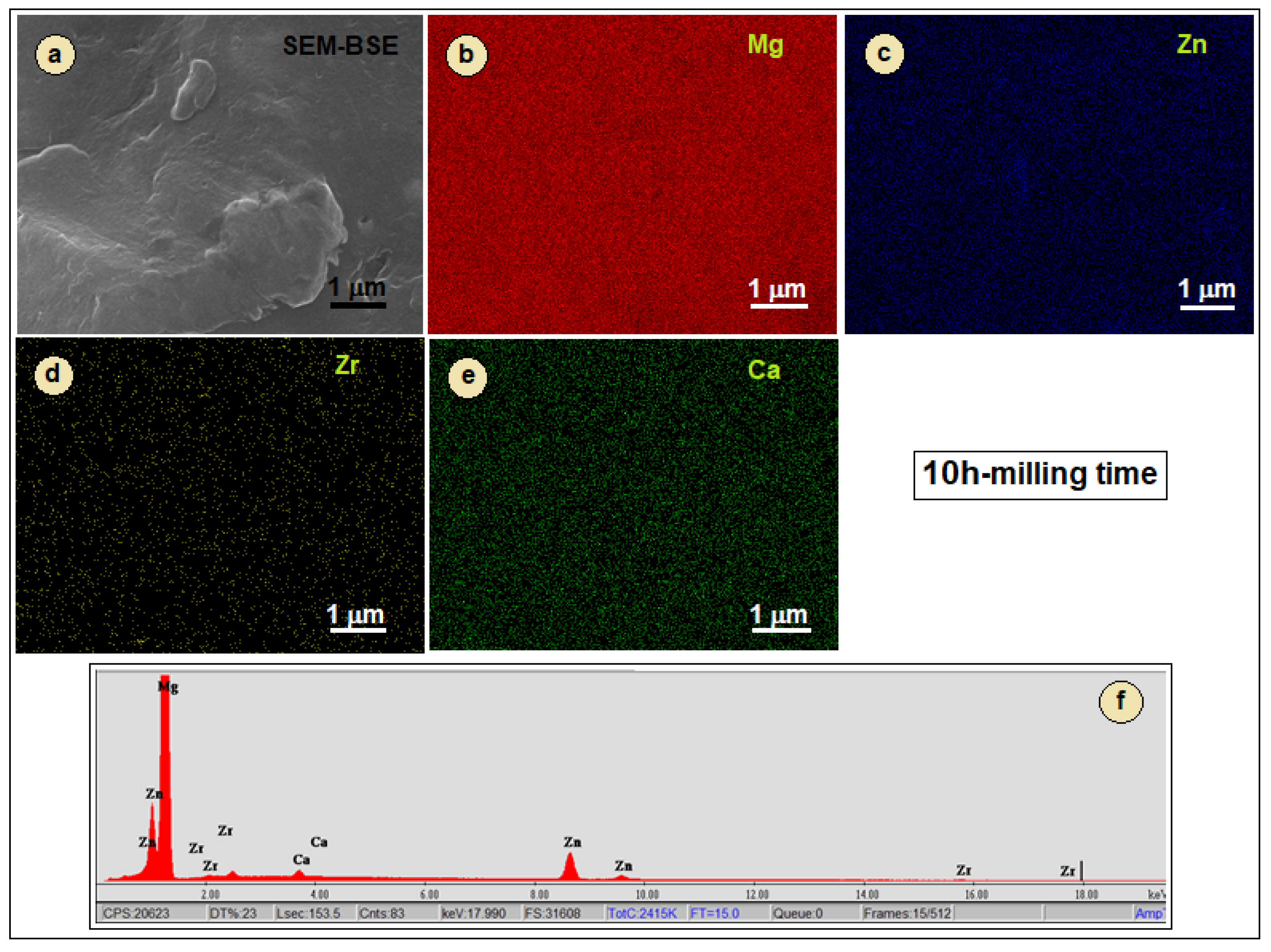
Apart from these morphological and dimensional considerations, the subsequent SEM-EDS analysis (Figure 8, Figure 9 and Figure 10) completes the above findings with more information regarding the structural evolution of the powders obtained by mechanical alloying. In order to make the workspace more efficient, it has been considered useful to show only significant results from all analysed samples. Thus, the SEM-EDS analysis only for three of five variants in the experimental package are shown: for the first value of the milling time—2 h, for the middle one—6 h, and for the final one—10 h.
The EDS results indicate the distribution map of alloying elements and the chemical composition of the powder-alloys, which does not change drastically between the processed variants, meaning that the alloying elements were almost homogeneously distributed during the milling process.
Typical distribution maps for the used alloying elements (Mg, Zn, Zr, and Ca), within microstructures of the obtained powder-alloys, are presented in Figure 8, Figure 9 and Figure 10a,e. It can be observed also that all main alloying elements show a uniform distribution within the microstructure. The fact that a very small microstructural formation with a higher Zr content appears in Figure 8 and Figure 9, probably representing traces of pure yet unhomogenized powder, can be considered a fortuitous case and not found in the XRD spectra. In Figure 10, however, for the version with 10 h of milling time, the SEM-EDS distribution of the alloying elements is clearly homogeneous, without traces of inhomogeneities.
Table 3 indicates the calculated average chemical composition, resulting from EDS analysis, for all tested variants. The values presented are within those initially established for the study alloy. Due to the SEM-EDS technique limitations, the presences of O and other elements with a low atomic number (Z) were not quantified.
Considering the entire experimental program presented, with all five variants of grinding time, it can be concluded that the last variant presents a quasi-adequate morphology for the application of the SLM process for which a fine, homogeneous, and almost spherical powder is generally required. Therefore, an SLM test has been applied for some preliminary results.

3.2. Preliminary Results for the SLM-Processed Sample from Powders Obtained by Mechanical Alloying with 10 h Milling Time

Although the declared objective of the work was to study the microstructural and morphological evolution of the powder during the mechanical alloying process, it was also considered a secondary objective to preliminarily test the SLM process applied to the last mechanical alloying variant, the one with the largest milling time—10 h (used parameters: 300 rpm/10 h/10:1).
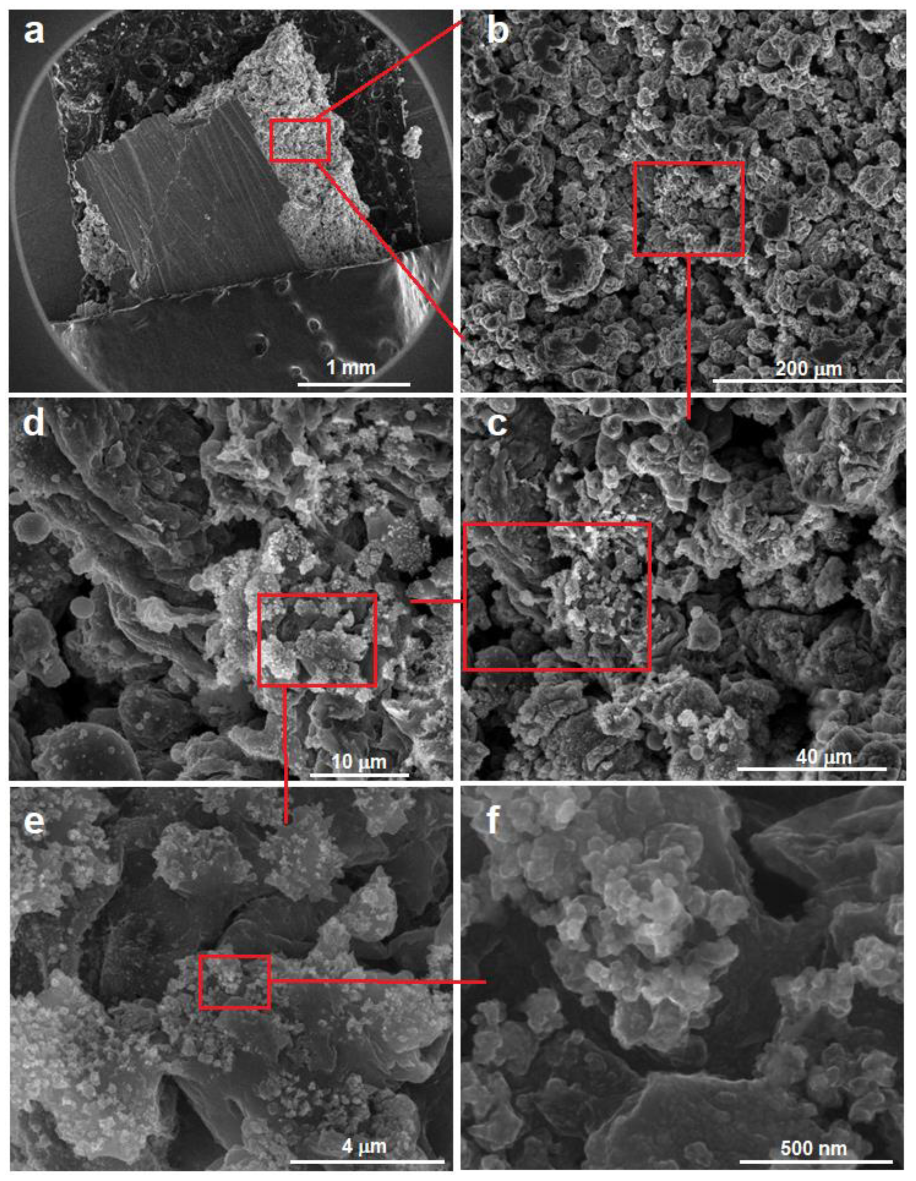
Figure 11 shows the surface morphology of the obtained SLM sample, by increasing step by step the magnification of the images. It can be considered that the obtained SLM sample presents a robust and non-brittle morphology, without a signalled balling effect, even if the powder should have a perfectly spherical morphology according to most reports in the specialized literature [27,62]. Therefore, the present SLM study, though preliminary, can be considered as having a promising result.
In addition, nine compression tests were performed on the Mg-Zn-Ca-Zr alloy in SLM conditions; the mechanical testing was performed considering the repeatability and reproducibility of the mechanical characteristics on a batch of nine samples. Figure 12 shows a typical stress–strain curve for the alloy in SLM conditions and typical sample geometry. As may be observed, the compressive yield stress was about 250 MPa and the ultimate compressive strength was 340 MPa. The elongation of the Mg-Zn-Ca-Zr alloy in SLM conditions is low, but this is a general characteristic for SLM alloys. The obtained mechanical characteristics, compared with other biodegradable materials, such as ceramics, polymers, and bioactive glasses, show that the Mg-Zn-Ca-Zr alloy can provide sufficient mechanical support at the early stage of bone reconstruction.

4. Conclusions

The main results of the current study can be concluded as follows:
(a)
The mechanical alloying method was applied to obtain the Mg-10Zn-0.5Zr-0.8Ca powder-alloy using different milling times. The morphologies of the milled powders reveal that the particles dimensions vary, with the average values ranging from 74.6 µm (after 2 h of milling process) to 16.2 µm (after 10 h of milling process).
(b)
During the milling process, the particles are subjected to repeated welding and fracturing. Strong plastic deformations occur, thus increasing the hardness, while at the same time the particle size decreases. The fluctuations in particle size are characteristic of the mechanical alloying process, as the particles are repeatedly subjected to cold welding, fracturing, and milling. This repetitive process results in a high homogeneity of chemical composition, which is supported by EDS analysis.
(c)
It can be concluded that mechanical alloying has utility for achieving homogeneity of the alloy and microstructure refinement which is desirable for enhancing the alloy’s performances. However, the alloying chemical elements—Zn, Zr, and Ca—introduced in the Mg-based solid solution and possible local variations in the composition can create a distribution of d-spacing for the crystallographic plane, which conducts to a value of 0.236% for the lattice strain; in the studied case, it is presumed to be produced by residual stresses, dislocations, and any other defect that causes a nonuniform lattice distortion in the crystal.
(d)
The SLM trial has promising results, proven by SEM analysis for the microstructural aspects, and proven also by results obtained by mechanical tests.

Author Contributions

Conceptualization, D.R. and A.N.; methodology, V.D.C.; software, V.D.C.; validation, D.R., V.D.C. and A.N.; formal analysis, D.S.; investigation, N.S., S.I., C.T.-R., R.E.H., R.S.C. and S.I.D.; writing—original draft preparation, A.N.; writing—review and editing, A.N. and D.R.; visualization, V.D.C.; supervision, D.R.; project administration, D.R.; funding acquisition, V.D.C. All authors have read and agreed to the published version of the manuscript.

Funding

This research was funded by the Romanian National Authority for Scientific Research, CCCDI—UEFISCDI, Project ERANET-MANUNET-AMMBI/grant no. 207/2020.

Institutional Review Board Statement

Not applicable.

Informed Consent Statement

Not applicable.

Data Availability Statement

The data presented in this study are available on request from the corresponding author.

Acknowledgments

The authors acknowledge financial support for this research by the Romanian National Authority for Scientific Research CCCDI–UEFISCDI, Project ERANET-MANUNET-AMMBI/grant no. 207/2020.

Conflicts of Interest

The authors declare no conflict of interest. The funders had no role in the design of the study; in the collection, analyses, or interpretation of data; in the writing of the manuscript; or in the decision to publish the results.

References

  1. Witte, F. Reprint of: The history of biodegradable magnesium implants: A review. Acta Biomater. 2015, 23, S28–S40. [Google Scholar] [CrossRef] [PubMed]
  2. Dziki, J.L.; Badylak, S.F. Immunomodulatory biomaterials. Curr. Opin. Biomed. Eng. 2018, 6, 51–57. [Google Scholar]
  3. Hassan, S.F.; Islam, M.T.; Saheb, N.; Baig, M.M.A. Magnesium for Implants: A Review on the Effect of Alloying Elements on Biocompatibility and Properties. Materials 2022, 15, 5669. [Google Scholar] [CrossRef] [PubMed]
  4. Chen, J.; Xu, Y.; Kolawole, S.K.; Wang, J.; Su, X.; Tan, L.; Yang, K. Systems, Properties, Surface Modification and Applications of Biodegradable Magnesium-Based Alloys: A Review. Materials 2022, 15, 5031. [Google Scholar] [CrossRef]
  5. Zhao, D.; Witte, F.; Lu, F.; Wang, J.; Li, J.; Qin, L. Current status on clinical applications of magnesium-based orthopaedic implants: A review from clinical translational perspective. Biomaterials 2017, 112, 287–302. [Google Scholar] [CrossRef]
  6. Li, Y.; Wang, Y.; Shen, Z.; Miao, F.; Wang, J.; Sun, Y.; Zhu, S.; Zheng, Y.; Guan, S. A biodegradable magnesium alloy vascular stent structure: Design, optimisation and evaluation. Acta Biomater. 2022, 142, 402–412. [Google Scholar] [CrossRef]
  7. Chen, Y.T.; Hung, F.Y.; Lin, Y.L.; Lin, C.Y. Biodegradation ZK50 magnesium alloy compression screws: Mechanical properties, biodegradable characteristics and implant test. J. Orthop. Sci. 2020, 25, 1107–1115. [Google Scholar]
  8. Li, L.; Zhang, M.; Li, Y.; Zhao, J.; Qin, L.; Lai, Y. Corrosion and biocompatibility improvement of magnesium-based alloys as bone implant materials: A review. Regen. Biomater. 2017, 4, 129–137. [Google Scholar]
  9. Yang, K.; Zhou, C.; Fan, H.; Fan, Y.; Jiang, Q.; Song, P.; Fan, H.; Chen, Y.; Zhang, X. Bio-Functional Design, Application and Trends in Metallic Biomaterials. Int. J. Mol. Sci. 2017, 19, 24. [Google Scholar] [CrossRef] [Green Version]
  10. Chang, G.; Regatte, R.R.; Schweitzer, M.E. Olympic fencers: Adaptations in cortical and trabecular bone determined by quantitative computed tomography. Osteoporos. Int. 2009, 20, 779–785. [Google Scholar]
  11. Okazaki, Y.; Gotoh, E.; Mori, J. Strength-Durability Correlation of Osteosynthesis Devices Made by 3D Layer Manufacturing. Materials 2019, 12, 436. [Google Scholar] [CrossRef] [Green Version]
  12. Haude, M.; Ince, H.; Abizaid, A.; Toelg, R.; Lemos, P.A.; Birgelen, C.V.; Christiansen, E.H.; Wijns, W.; Neumann, F.J.; Kaiser, C. Safety and performance of the second-generation drug-eluting absorbable metal scaffold in patients with de-novo coronary artery lesions (BIOSOLVE-II): 6 months results of a prospective, multi centre, non-randomised, first-in-mantrial. Lancet 2015, 387, 31–39. [Google Scholar] [CrossRef]
  13. Plaass, C.; Von, F.C.; Ettinger, S.; Sonnow, L.; Calderone, F.; Weizbauer, A.; Reifenrath, J.; Claassen, L.; Waizy, H.; Daniilidis, K. Bioabsorbable magnesium versus standard titanium compression screws for fixation of distal metatarsal osteotomies–3 years results of a randomized clinical trial. J. Orthop. Sci. 2018, 23, 321–327. [Google Scholar] [CrossRef] [PubMed]
  14. Lee, J.W.; Han, H.S.; Han, K.J.; Park, J.; Jeon, H.; Ok, M.R.; Seok, H.K.; Ahn, J.P.; Lee, K.E.; Lee, D.H.; et al. Long-term clinical study and multiscale analysis of in vivo biodegradation mechanism of Mg alloy. Proc. Natl. Acad. Sci. USA 2016, 113, 716–721. [Google Scholar] [CrossRef] [PubMed]
  15. Qin, Y.; Wen, P.; Guo, H.; Xia, D.; Zheng, Y.; Jauer, L.; Poprawe, R.; Voshage, M.; Schleifenbaum, J.H. Additive manufacturing of biodegradable metals: Current research status and future perspectives. Acta Biomater. 2019, 98, 3–22. [Google Scholar] [CrossRef]
  16. Yazdimamaghani, M.; Razavi, M.; Vashaee, D.; Moharamzadeh, K.; Boccaccini, A.R.; Tayebi, L. Porous magnesium-based scaffolds for tissue engineering. Mater. Sci. Eng. C Mater. Biol. Appl 2017, 71, 1253–1266. [Google Scholar] [CrossRef] [Green Version]
  17. Salleh, E.M.; Ramakrishnan, S.; Hussain, Z. Synthesis of Biodegradable Mg-Zn Alloy by Mechanical Alloying: Effect of Milling Time. Procedia Chem. 2016, 19, 525–530. [Google Scholar] [CrossRef] [Green Version]
  18. Lesz, S.; Hrapkowicz, B.; Karolus, M.; Gołombek, K. Characteristics of the Mg-Zn-Ca-Gd Alloy after Mechanical Alloying. Materials 2021, 14, 226. [Google Scholar] [CrossRef]
  19. Lovašiová, P.; Lovaši, T.; Kubásek, J.; Jablonská, E.; Msallamová, Š.; Michalcová, A.; Vojtěch, D.; Suchý, J.; Koutný, D.; Ghassan Hamed Alzubi, E. Biodegradable WE43 Magnesium Alloy Produced by Selective Laser Melting: Mechanical Properties, Corrosion Behavior, and In-Vitro Cytotoxicity. Metals 2022, 12, 469. [Google Scholar] [CrossRef]
  20. Sing, S.L.; An, J.; Yeong, W.Y.; Wiria, F.E. Laser and electron-beam powder-bed additive manufacturing of metallic implants: A review on processes, materials and designs. J. Orthop. Res. 2016, 34, 369–385. [Google Scholar] [CrossRef]
  21. Andani, M.T.; Shayesteh Moghaddam, N.; Haberland, C.; Dean, D.; Miller, M.J.; Elahinia, M. Metals for bone implants. Part1. Powder metallurgy and implant rendering. Acta Biomater. 2014, 10, 4058–4070. [Google Scholar] [CrossRef]
  22. Sezer, N.; Evis, Z.; Kayhan, S.M.; Tahmasebifar, A.; Koç, M. Review of magnesium-based biomaterials and their applications. J. Magnes. Alloys 2018, 6, 23–43. [Google Scholar] [CrossRef]
  23. Abbasi, M.; Sajjadi, S.A.; Azadbeh, M. An investigation on the variations occurring during Ni3Al powder formation by mechanical alloying technique. J. Alloys Compd. 2010, 497, 171–175. [Google Scholar] [CrossRef]
  24. Neves, F.; Fernandes, F.M.B.; Martins, I.; Correia, J.B. Parametric optimization of Ti–Ni powder mixtures produced by mechanical alloying. J. Alloys Compd. 2011, 509, 271–274. [Google Scholar] [CrossRef]
  25. Zheng, Y.F.; Gu, X.N.; Witte, F. Biodegradable metals. Mat. Sci. Eng. R 2014, 77, 1–34. [Google Scholar] [CrossRef]
  26. Liu, S.; Guo, H. Balling Behavior of Selective Laser Melting (SLM) Magnesium Alloy. Materials 2020, 13, 3632. [Google Scholar] [CrossRef] [PubMed]
  27. Suryanarayana, C. Mechanical Alloying: A Novel Technique to Synthesize Advanced Materials. Research 2019, 2019, 4219812. [Google Scholar] [CrossRef] [Green Version]
  28. Ng, C.C.; Savalani, M.M.; Man, H.C.; Gibson, I. Layer manufacturing of magnesium and its alloy structures for future applications. Virtual Phys. Prototyp. 2010, 5, 13–19. [Google Scholar] [CrossRef]
  29. Ng, C.C.; Savalani, M.M.; Lau, M.L.; Man, H.C. Microstructure and mechanical properties of selective laser melted magnesium. Appl. Surf. Sci. 2011, 257, 7447–7454. [Google Scholar] [CrossRef]
  30. Dziuba, D.; Meyer-Lindenberg, A.; Seitz, J.M.; Waizy, H.; Angrisani, N.; Reifenrath, J. Long-term in vivo degradation behaviour and biocompatibility of the magnesium alloy ZEK100 for use as a biodegradable bone implant. Acta Biomater. 2013, 9, 8548–8560. [Google Scholar] [CrossRef] [PubMed]
  31. Shuai, C.; Yang, Y.; Wu, P.; Lin, X.; Liu, Y.; Zhou, Y.; Feng, P.; Liu, X.; Peng, S. Laser rapid solidification improves corrosion behavior of Mg-Zn-Zr alloy. J. Alloys Compd. 2017, 691, 961–969. [Google Scholar] [CrossRef]
  32. Zumdick, N.A.; Jauer, L.; Kersting, L.C.; Kutz, T.N.; Schleifenbaum, J.H.; Zander, D. Additive manufactured WE43 magnesium: A comparative study of the microstructure and mechanical properties with those of powder extruded and as-cast WE43. Mater. Charact. 2019, 147, 384–397. [Google Scholar] [CrossRef]
  33. Kraus, T.; Fischerauer, S.F.; Hänzi, A.C.; Uggowitzer, P.J.; Löffler, J.F.; Weinberg, A.M. Magnesium alloys for temporary implants in osteosynthesis: In vivo studies of their degradation and interaction with bone. Acta Biomater. 2012, 8, 1230–1238. [Google Scholar] [CrossRef] [PubMed]
  34. Minárik, P.; Král, R.; Pešička, J.; Daniš, S.; Janeček, M. Microstructure characterization of LAE442 magnesium alloy processed by extrusion and ECAP. Mater. Charact. 2016, 112, 1–10. [Google Scholar]
  35. Minárik, P.; Jablonska, E.; Král, R.; Lipov, J.; Ruml, T.; Blawert, C.; Hadzima, B.; Chmelík, F. Effect of equal channel angular pressing on in vitro degradation of LAE442 magnesium alloy. Mater. Sci. Eng. C 2017, 73, 736–742. [Google Scholar] [CrossRef]
  36. Erdmann, N.; Angrisani, N.; Reifenrath, J.; Lucas, A.; Thorey, F.; Bormann, D.; Meyer-Lindenberg, A. Biomechanical testing and degradation analysis of MgCa0.8 alloy screws: A comparative in vivo study in rabbits. Acta Biomater. 2011, 7, 1421–1428. [Google Scholar] [CrossRef]
  37. Zhao, D.; Wang, T.; Nahan, K.; Guo, X.; Zhang, Z.; Dong, Z.; Chen, S.; Chou, D.T.; Hong, D.; Kumta, P.N.; et al. In vivo characterization of magnesium alloy biodegradation using electrochemical H2monitoring, ICP-MS, and XPS. Acta Biomater. 2017, 50, 556–565. [Google Scholar] [CrossRef]
  38. Wang, J.; Wu, Y.; Li, H.; Liu, Y.; Bai, X.; Chau, W.; Zheng, Y.; Qin, L. Magnesium alloy-based interference screw developed for ACL reconstruction attenuates peri-tunnel bone loss in rabbits. Biomaterials 2018, 157, 86–97. [Google Scholar] [CrossRef]
  39. Wang, G.; Huang, G.; Chen, X.; Deng, Q.; Tang, A.; Jiang, B.; Pan, F. Effects of Zn addition on the mechanical properties and texture of extruded Mg-Zn-Ca-Ce magnesium alloy sheets. Mater. Sci. Eng. A 2017, 705, 46–54. [Google Scholar] [CrossRef]
  40. Yuasa, M.; Hayashi, M.; Mabuchi, M.; Chino, Y. Improved plastic anisotropy of Mg–Zn–Ca alloys exhibiting high-stretch formability: A first-principles study. Acta Mater. 2014, 65, 207–214. [Google Scholar] [CrossRef]
  41. Hrapkowicz, B.; Lesz, S.; Karolus, M.; Garbiec, D.; Wi´sniewski, J.; Rubach, R.; Gołombek, K.; Kremzer, M.; Popis, J. Microstructure and Mechanical Properties of Spark Plasma Sintered Mg-Zn-Ca-Pr Alloy. Metals 2022, 12, 375. [Google Scholar] [CrossRef]
  42. Alateyah, A.I.; Alawad, M.O.; Aljohani, T.A.; El-Garaihy, W.H. Effect of ECAP Route Type on the Microstructural Evolution, Crystallographic Texture, Electrochemical Behavior and Mechanical Properties of ZK30 Biodegradable Magnesium Alloy. Materials 2022, 15, 6088. [Google Scholar] [CrossRef]
  43. Zhang, B.; Liao, H.; Coddet, C. Effects of processing parameters on properties of selective laser melting Mg–9%Al powder mixture. Mater. Des. 2012, 34, 753–758. [Google Scholar] [CrossRef]
  44. Pawlak, A.; Chlebus, E. Process parameter optimization of Laser Micrometallurgy of AZ31 alloy. Interdiscip. J. Eng. Sci. 2015, 3, 10–15. [Google Scholar]
  45. Pawlak, A.; Szymczyk, P.E.; Kurzynowski, T.; Chlebus, E. Selective laser melting of magnesium AZ31B alloy powder. Rapid Prototyp. J. 2020, 26, 249–258. [Google Scholar] [CrossRef]
  46. Pawlak, A.; Rosienkiewicz, M.; Chlebus, E. Design of experiments approach in AZ31 powder selective laser melting process optimization. Arch. Civ. Mech. Eng. 2017, 17, 9–18. [Google Scholar] [CrossRef]
  47. He, C.; Bin, S.; Wu, P.; Gao, C.; Feng, P.; Yang, Y.; Liu, L.; Zhou, Y.; Zhao, M.; Yang, S.; et al. Microstructure evolution and biodegradation behavior of laser rapid solidified Mg–Al–Zn Alloy. Metals 2017, 7, 105. [Google Scholar] [CrossRef] [Green Version]
  48. Shuai, C.; He, C.; Feng, P.; Guo, W.; Gao, C.; Wu, P.; Yang, Y.; Bin, S. Biodegradation mechanisms of selective laser-melted Mg–xAl–Zn alloy: Grain size and intermetallic phase. Virtual Phys. Prototyp. 2017, 13, 59–69. [Google Scholar] [CrossRef]
  49. Bahman, H.; Abdollah, A. Microstructure, mechanical properties, corrosion behavior and cytotoxicity of Mg-Zn-Al-Ca alloys as biodegradable materials. J. Alloys Compd. 2014, 607, 1–10. [Google Scholar]
  50. El-Garaihy, W.H.; Alateyah, A.I.; Alawad, M.O.; Aljohani, T.A. Improving the Corrosion Behavior and Mechanical Properties of Biodegradable Mg-Zn-Zr Alloys through ECAP for Usage in Biomedical Applications. In Magnesium Technology; Springer: Cham, Switzerland, 2022; pp. 259–269. [Google Scholar]
  51. Xu, L.; Liu, X.; Sun, K.; Fu, R.; Wang, G. Corrosion Behavior in Magnesium-Based Alloys for Biomedical Applications. Materials 2022, 15, 2613. [Google Scholar] [CrossRef]
  52. Li, Z.; Gu, X.; Lou, S.; Zheng, Y. The development of binary Mg-Ca alloys for use as biodegradable materials within bone. Biomaterials 2008, 29, 1329–1344. [Google Scholar] [CrossRef] [PubMed]
  53. Salahshoor, M.; Guo, Y.B. Surface integrity of biodegradable Magnesium-Calcium orthopedic implant by burnishing. J. Mech. Behav. Biomed. Mater. 2011, 4, 1888–1904. [Google Scholar] [PubMed]
  54. Lee, C.D.; Kang, C.S.; Shin, K.S. Effect of galvanic corrosion between precipitate and matrix on corrosion behavior of as-cast magnesium-aluminum alloys. Met. Mater. Int. 2000, 6, 351–358. [Google Scholar] [CrossRef]
  55. Gandel, D.S.; Easton, M.A.; Gibson, M.A.; Abbott, T.; Birbilis, N. The influence of zirconium additions on the corrosion of magnesium. Corros. Sci. 2014, 81, 27–35. [Google Scholar] [CrossRef]
  56. Gandel, D.S.; Easton, M.A.; Gibson, M.A.; Abbott, T.; Birbilis, N. The influence of Mg-Zr master alloy microstructure on the corrosion of Mg. In Magnesium Technology 2013; The Minerals, Metals & Materials Society; Springer: Cham, Switzerland, 2013; pp. 157–162. [Google Scholar]
  57. Ding, Y.; Li, Y.; Lin, J.; Wen, C. Effects of zirconium and strontium on the biocorrosion of Mg-Zr-Sr alloys for biodegradable implant applications. J. Mater. Chem. B 2015, 3, 3714–3729. [Google Scholar] [CrossRef] [PubMed]
  58. Bobby Kannan, M.; Singh Raman, R.K. In vitro degradation and mechanical integrity of calcium-containing magnesium alloys in modified-simulated body fluid. Biomaterials 2008, 29, 2306–2314. [Google Scholar] [CrossRef]
  59. Du, W.; Liu, K.; Ma, K.; Wang, Z.; Li, S. Effects of trace Ca/Sn addition on corrosion behaviors of biodegradable Mg–4Zn–0.2Mn alloy. J. Magnes. Alloys 2018, 6, 1–14. [Google Scholar] [CrossRef]
  60. Rietveld, H.M. Line Profiles of Neutron Powder-Diffraction Peaks for Structure Refinement. Acta Cryst. 1967, 22, 151–152. [Google Scholar]
  61. Kawano, S.; Iikubo, S.; Ohtani, H. Thermodynamic Stability of Mg-Based Laves Phases. Mater. Trans. 2018, 59, 890–896. [Google Scholar] [CrossRef]
  62. Ma, E. Alloys created between immiscible metals. Prog. Mater. Sci. 2005, 50, 413–509. [Google Scholar]
Figure 1. The schema of the experimental procedures and of corresponding analyses applied on the studied Mg-Zn-Zr-Ca powder-alloy.
Crystals 12 01641 g001
Figure 2. XRD analysis of the powder-alloy samples processed by mechanical alloying for 2 h milling time (a), and for 10 h milling time (b).
Crystals 12 01641 g002
Figure 3. Δ(2θ) graph for identifying the unit-cell parameters.
Crystals 12 01641 g003
Figure 4. Graph for crystallite size determination of the powder-alloy sample.
Crystals 12 01641 g004
Figure 5. SEM images of the powder-alloy samples processed by mechanical alloying for different milling time: (ac) 2 h/300 rpm, and different magnifications; (df) 4 h/300 rpm, and different magnifications; (gi) 6 h/300 rpm, different magnifications.
Crystals 12 01641 g005
Figure 6. SEM images of the powder-alloy samples processed by mechanical alloying for different milling time: (ac) 8 h/300 rpm, and different magnifications; (df) 10 h/300 rpm, and different magnifications.
Crystals 12 01641 g006
Figure 7. Average particle size (µm) for the powder-alloy processed by mechanical alloying for different milling time: 2 h, 4 h, 6 h, 8 h and 10 h.
Crystals 12 01641 g007
Figure 8. Distribution map of alloying elements for the powder-alloy processed by mechanical alloying at 2 h/300 rpm: (a) SEM image of the powder; (b) SEM-EDS distribution of Mg; (c) SEM-EDS distribution of Zn; (d) SEM-EDS distribution of Zr; (e) SEM-EDS distribution of Ca; (f) global EDS spectra.
Crystals 12 01641 g008
Figure 9. Distribution map of alloying elements for the powder-alloy processed by mechanical alloying at 6 h/300 rpm: (a) SEM image of the powder; (b) SEM-EDS distribution of Mg; (c) SEM-EDS distribution of Zn; (d) SEM-EDS distribution of Zr; (e) SEM-EDS distribution of Ca; (f) global EDS spectra.
Crystals 12 01641 g009
Figure 10. Distribution map of alloying elements for the powder-alloy processed by mechanical alloying at 10 h/300 rpm: (a) SEM image of the powder; (b) SEM-EDS distribution of Mg; (c) SEM-EDS distribution of Zn; (d) SEM-EDS distribution of Zr; (e) SEM-EDS distribution of Ca; (f) global EDS spectra.
Crystals 12 01641 g010
Figure 11. The SEM-SE images for the studied Mg-based powder-alloy after processing by selective laser melting—SLM. (from af) the same sample, with gradual increase in magnification.
Crystals 12 01641 g011
Figure 12. Stress-strain curve after compressive testing applied on the Mg-10Zn-0.8Ca-0.5Zr alloy processed by SLM.
Crystals 12 01641 g012
Table 1. The identified peak list in the range of 30–55 degrees for 2Θ.
2Θ [°]d [Å]FWHM, [°]
Full Width at Half Maximum of the Peak
Crystallite Size, [Å]
132.1682.78040.301287
234.4082.60430.329264
336.6212.45180.3193273.7
440.2262.24010.49181
547.8391.89980.3961229.1
Table 2. Average particle size for the studied powder-alloy for varied milling times.
Milling Time [h]
2 h4 h6 h8 h10 h
Average particle size [µm] ± Standard Deviation74.6 µm ± 22.524.7 µm ± 18.816.6 µm ± 10.218.9 µm ± 12.416.2 µm ± 9.3
Table 3. Average chemical compositions of the powder-alloy obtained by EDS analysis for all applied variants of the mechanical alloying process.
Milling TimeAlloying Elements, [% wt.]
MgZnZrCa
2 h89.6 ± 3.09.3 ± 1.70.32 ± 0.100.78 ± 0.20
4 h89.5 ± 3.09.4 ± 1.60.36 ± 0.100.74 ± 0.20
6 h89.1 ± 3.09.6 ± 1.60.48 ± 0.100.82 ± 0.20
8 h88.9 ± 3.09.8 ± 1.70.51 ± 0.100.79 ± 0.20
10 h88.7 ± 3.010.0 ± 1.70.51 ± 0.100.79 ± 0.20
Publisher’s Note: MDPI stays neutral with regard to jurisdictional claims in published maps and institutional affiliations.