Abstract
Lately, ceramic fuel cells (CFCs) have held exceptional promise for joint small- and large-scale applications. However, the low-oxygen reduction response of cathode materials has hindered the low operating temperature of CFCs. Herein, we have developed a semiconductor based on La and Ce co-doped SrCoO3 and embedded them in porous Ni-foam to study their electrochemical properties. The porous Ni-foam-pasted La0.2Sr0.8Co0.8Ce0.2O3‒δ cathode displays small-area-specific resistance and excellent ORR (oxygen reduction reaction) activity at low operating temperatures (LT) of 450–500 °C. The proposed device has delivered an impressive fuel cell performance of 440 mW-cm−2, using La0.2Sr0.8Co0.8Ce0.2O3−δ embedded on porous Ni-foam substrate cathode operation at 550 °C with H2 fuel and atmospheric air. It even can function well at a lower temperature of 450 °C. Moreover, La0.2Sr0.8Co0.8Ce0.2O3−δ embedded on porous Ni-foam shows very good activation energy compared to individual SrCoO3 and La0.1Sr0.9Co0.9Ce0.1O3−δ embedded on porous Ni-foam, which help to promote ORR activity. Different characterization has been deployed, likewise: X-ray diffraction, photoelectron-spectroscopy, and electrochemical impedance spectroscopy for a better understanding of improved ORR electrocatalytic activity of prepared La0.2Sr0.8Co0.8Ce0.2O3−δ embedded on porous Ni-foam substrate. These results can further help to develop functional cobalt-free electrocatalysts for LT-SOFCs.
1. Introduction
Addressing global energy demand and environmental pollution control requires an alteration to the current energy system by eliminating/removing the dependence on fossil fuels. Renewable energy, including solar, wind, and tidal, is gradually moving to mainstream power with a large capacity that exceeds the global energy consumption [1,2]. However, these energy forms’ inherent discontinuity and intermittency plague integration with electrical infrastructure. Ceramic fuel cells show increasing potential to overcome these obstacles, with a more efficient way to achieve electricity from hydrogen or hydrocarbon fuels to address complicated and various demands in current scenarios [3,4].
The excellent oxygen reduction reaction (ORR) electrocatalysts are vital for ceramic fuel cells, including SOFCs and PCFCs, as sluggish ORR kinetics limit the efficiency of these devices. The efficiency of SOFCs is especially highly targeted at low operating temperatures [2], while high operating temperatures (700–1000 °C) carry many drawbacks, making the technology more complex and limiting its widespread applications [3]. Therefore, the most important factor is to reduce the operating temperature into the range of 300–600 °C to advance SOFCs toward commercialization [4]. However, the high temperature is considered to be vital to achieve high enough ORR activity in currently used PCFC cathode materials [5,6,7]. Therefore, intensive efforts have been made to develop advanced PCFC cathode materials operating at LTs. However, many serious challenges are still present [7,8].
Generally, a suitable cation doping strategy to the A or B site is used in perovskite-oxides to induce mixed ionic–electronic (MIE) conduction to raise ORR activity. To date, Ba1−xSrxCo1−yFeyO3 (BSCF), La0.6Sr0.4Co0.8Fe0.2O3−δ (LSCF), Pr0.8Ba0.2CoO3, BaCoxFe1−xO3−δ and BaCo0.4Fe0.4Zr0.1Y0.1O3−δ perovskite have been developed with the most state-of-the-art cathodes for SOFCs [9,10,11,12,13,14,15]. Most state-of-the-art cathodes of SOFCs contain higher levels of Co, but their structural stability is challenging because of their large TECs (thermal expansion coefficients) [16]. Therefore, over the last decade, extensive efforts have been made toward Co-free cathodes, and Fe-based materials have gained substantial attention as an alternative because of their better structural stability [17].
In this work, apart from the conventional doping, we have developed a semiconductor cathode based on La-doping on the A-site, and Ce-doping on the B-site, of SrCoO3 perovskite. Later, La0.2Sr0.8Co0.8Ce0.2O3−δ particles were embedded on a porous Ni-foam substrate and their properties were studied as ORR electrocatalysts in an LT-SOFC cathode. The prepared La0.2Sr0.8Co0.8Ce0.2O3−δ embedded on porous Ni-foam substrate shows excellent ORR activity and power output while operating at 450–550 °C. Various spectroscopic characterizations were used to understand the promoted electrocatalytic activity of La0.2Sr0.8Co0.8Ce0.2O3−δ embedded on a porous Ni-foam substrate. However, we have found that this study would take a step forward in developing advanced ORR properties and some key heterostructure composites based on La0.2Sr0.8Co0.8Ce0.2O3−δ embedded on porous Ni-foam structural features towards ORR mechanism.
2. Materials and Methods
2.1. Synthesis Procedures
La- and Ce-doped SrCoO3 perovskite-structured residues were made using the sol–gel technique. In the sol–gel method, citric acid and ethylenediaminetetraacetic acid (EDTA) are used as complexing agents. In the first step, 0.1 moles of EDTA were dissolved in de-ionized H2O. Subsequently, an ammonia solution was added to the solution to set the pH to 7.0 and make the solution transparent. After a while, suitable amounts of Sr (NO3)2.6H2O, La (NO3)2.6H2O, Co (NO3)2.9H2O, and Ce (NO3)2.9H2O bought from Alfa Aesar with 99.98% purity were detached into the solution. Afterward, 0.1 moles of citric acid were added to the above-prepared solution. Then, later, the solution was continuously stirred at 240 rpm at 80 °C for 8 h, resulting in the brownish gel of La0.2Sr0.8Co0.8Ce0.2O3−δ. Subsequently, the brownish gel was dried at 150 °C in an oven. In the end, the dried gel was fired at 1000 °C for 8 h in the air. The pure SrCoO3 and La0.1Sr0.9Co0.9Ce0.1O3−δ were prepared using the same protocols as stated earlier for the comparative study.
2.2. Characterizations Tools and Electrochemical Measurements
A Bruker D8 X-ray diffractometer with Cu-Kα radiation (λ = 1.5418 Å) was employed to evaluate the X-ray diffraction pattern of prepared powders of SrCoO3, La0.1Sr0.9Co0.9Ce0.1O3−δ, and La0.2Sr0.8Co0.8Ce0.2O3−δ. Merlin compacts (Zeiss, Goeschwitzer Strasse 51-5207745 Jena, Germany) were used to perform scanning electron microscopy (SEM) to study the morphology of proposed materials. Surface properties and chemical oxidation of the SrCoO3, La0.1Sr0.9Co0.9Ce0.1O3−δ, and La0.2Sr0.8Co0.8Ce0.2O3−δ were evaluated via employing X-ray photoelectron spectroscopy (Physical Electronics Quantum 2000) with an Al Kα X-ray source at room temperature in an ultra-high vacuum (UHV). XPS peaks were fitted using Peak 41. The Gamry Reference 3000, USA workstation was set to study the EIS (electrochemical impedance spectroscopy) spectra under the condition of OCV (open-circuit voltage) with 10 mV of dc signal over the frequency range of 0.1 to 106 Hz. The recorded data were analyzed using ZSIMPWIN software to be obtained as EIS data.
2.3. Complete Fabrication of Fuel Cells
To check and evaluate the feasibility of the prepared materials of SrCoO3, La0.1Sr0.9Co0.9Ce0.1O3−δ, and La0.2Sr0.8Co0.8Ce0.2O3−δ as an air electrode in SOFC, the fuel cell pellets were prepared by dry pressing. In the first step, SrCoO3, La0.1Sr0.9Co0.9Ce0.1O3−δ, and La0.2Sr0.8Co0.8Ce0.2O3−δ were mixed with the appropriate amount of terpinol. Then, the solution was mixed and painted on porous Ni-foam. The as-prepared SrCoO3, La0.1Sr0.9Co0.9Ce0.1O3−δ, and La0.2Sr0.8Co0.8Ce0.2O3−δ embedded on porous Ni-foam substrate were used as an air electrode, and Ni-foam Ni0.8Co0.15Al0.05LiO2−δ (NCAL-Ni-foam) from Tianjin Bamo Sci. & Tech. Joint Stock Ltd Tianjin China powders as fuel electrodes (anode) prepared by the same method used. In the next step, one piece was placed in a steel mold, followed by Gd0.1Ce0.9O2−δ electrolyte powders (0.20 g) and NCAL-Ni-foam, and pressed at 220 MPa to obtain three-layer devices. All types of fuel cells were fabricated using the same protocol. Afterward, the prepared fuel cell devices were heated at 600 °C for 4 h in Ar to obtain a dense electrolyte layer (≅relative density of 90%) to avoid gas leakage. Furthermore, a symmetrical cell with SrCoO3, La0.1Sr0.9Co0.9Ce0.1O3−δ, and La0.2Sr0.8Co0.8Ce0.2O3−δ electrodes over the GDC electrolyte was made for the measurements of ORR activity. The active area of all prepared pellets was 0.64 cm2. Demonstrated power density and EIS of single cells were performed, with 3% H2O humidified hydrogen fuel and air from the atmosphere as oxidants. The H2/air gases were supplied with a drift rate of approximately 100–120 ± 5% mL/min.
3. Results
3.1. Structure and Composition Analysis
Figure 1a illustrates the XRD pattern of SrCoO3, La0.1Sr0.9Co0.9Ce0.1O3−δ, and La0.2Sr0.8Co0.8Ce0.2O3−δ in the 2θ range from 10° to 90°. The attained peaks of the SrCoO3 diffraction pattern reside at different angles of 23, 32, 39, 46, 57, 68, and 76. The attained peaks are further correlated to the different planes of (100), (110), (111), (200), (211), (220), and (310), respectively, revealing the cubic structure with space group pm-3m (221), and lattice of a = b = C = 3.9 and α = β = γ 90° [18]. Moreover, Figure 1b depicts the comparative diffraction pattern of SrCoO3, La0.1Sr0.9Co0.9Ce0.1O3−δ, and La0.2Sr0.8Co0.8Ce0.2O3−δ in the 2θ range from 20 to 45°, where dominant diffraction peaks of La0.1Sr0.9Co0.9Ce0.1O3−δ and La0.2Sr0.8Co0.8Ce0.2O3−δ located at 2θ of 32° seem to be shifted towards a lower angle, which might be because of the high ionic radius of La3+ and Ce4+/3+ ion [19].
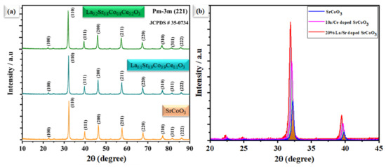
Figure 1.
(a) The X-ray diffraction pattern of SrCoO3, La0.1Sr0.9Co0.9Ce0.1O3−δ, and La0.2Sr0.8Co0.8Ce0.2O3−δ, respectively. (b) The comparison main of peak shifting of SrCoO3 with La and Ce doping.
Figure 2a,b shows the microscopic SEM image of La0.2Sr0.8Co0.8Ce0.2O3−δ at a different scale. The morphology of La0.2Sr0.8Co0.8Ce0.2O3−δ appears very fine and nanostructured. The La0.2Sr0.8Co0.8Ce0.2O3−δ shows a particle size in the range of ≤50 nm. Figure 3a shows the SEM image of La0.2Sr0.8Co0.8Ce0.2O3−δ dispersed on porous Ni-foam, where a porous structure with high porosity can be noticed, while Figure 3b–h shows the EDS mapping image of La0.2Sr0.8Co0.8Ce0.2O3−δ after embedding on Ni-foam. The EDS mapping image of each element in La0.2Sr0.8Co0.8Ce0.2O3−δ on porous Ni-foam confirms the presence of all elements. The basic mapping image of different features with mixed colors was used to reveal the chemical distribution by energy dispersive spectroscopy (EDS), where the homogenous chemical concentration of each element was confirmed, including Ni, La, Sr, Co, Ce, and O. Moreover, the mapping of the chemical distribution of each component individually is shown in Figure 4b, measured using an SEM image in Figure 4a, which could help estimate the chemical distribution [20,21].
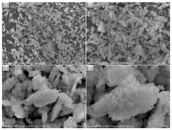
Figure 2.
(a–d) The surface morphology studied by SEM for La0.2Sr0.8Co0.8Ce0.2O3−δ powder at different scales, such as 10 µm−500 nm.
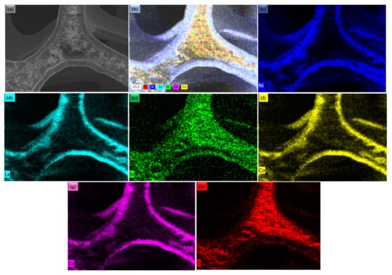
Figure 3.
(a) The surface morphology studied by SEM for La0.2Sr0.8Co0.8Ce0.2O3−δ embedded on porous Ni-foam substrate; (b–h) combined and individual EDS mapping image of Ni, La, Sr, Co, Ce and O in La0.2Sr0.8Co0.8Ce0.2O3−δ SEM image (a), respectively.
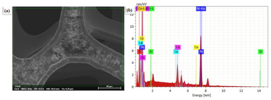
Figure 4.
The surface morphology and compositional investigations. (a) SEM image of La0.2Sr0.8Co0.8Ce0.2O3−δ particles planted on porous Ni-foam, (b) EDS image of La0.2Sr0.8Co0.8Ce0.2O3−δ embedded on porous Ni-foam as shown in Figure 3a.
3.2. Electrochemical Impedance and Electrical Conductivity
Cathodic polarization plays the largest contributing part in the entire impedance spectra of SOFCs. Hence, it is necessary to understand and determine the cathodic polarization process and the rate-determining step involved in ORR activity, and slow it down. To study the ORR properties of different La0.2Sr0.8Co0.8Ce0.2O3−δ embedded on porous Ni-foam, EIS characterization was carried out using electrochemical impedance spectroscopy, as shown in Figure 5. The EIS measured symmetrical cells in the air at 400–550 °C, under OCV conditions. The comparison with Nyquist plots of La0.2Sr0.8Co0.8Ce0.2O3−δ embedded on porous Ni-foam cells over GDC electrolytes obtained from EIS data at different operating temperatures is shown in Figure 5. The fitted model circuit of EIS results using Z-simpwin software suggests very low grain , and the grain boundary () prepared electrode La0.2Sr0.8Co0.8Ce0.2O3−δ embedded on porous Ni-foam cathode is very low at 550 °C, as shown in Figure 4a [22,23]. The fitted data describe two dominant polarization losses signified by the ASR at LF (low frequencies) and HF (high frequencies) [24–26]. ORR is described as a multistep process; (i) surface adsorption/gas diffusion and separation of O2 from the air, (ii) diffusion of Oad, (iii) conversion of absorbed O2 into O2− and (iv) transportation of O2− to the cathode/electrolyte interface. Step-by-step or parallel combinations of these processes could be involved [24,25]. However, low ASR in La0.2Sr0.8Co0.8Ce0.2O3−δ embedded on porous Ni-foam cathode could be the parallel combination of these steps. The large grain boundary in single-phase cathode materials plays a significant role in slowing down the ORR process. While very low grain resistance (Rg) of 0.08 is trialed, the resistance refers to grain boundary resistance () at 0.38 Ω cm2. Most often, oxygen vacancies are virtually studied in simply doped oxide materials at low temperatures of interest for applications [26], while the La0.2Sr0.8Co0.8Ce0.2O3−δ embedded on porous Ni-foam approach can be applied to enhance ORR activity and TPBs for developing SOFCs cathode. In addition, electrochemical impedance analysis signifies that oxygen’s surface exchange process is much more dominant than the bulk diffusion process of oxygen in La0.2Sr0.8Co0.8Ce0.2O3−δ embedded on porous Ni-foam.
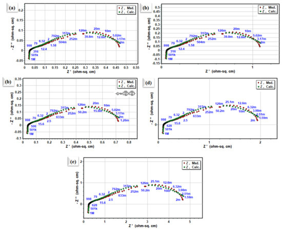
Figure 5.
Nyquist plot of impedance spectra for symmetrical electrode cell based on La0.2Sr0.8Co0.8Ce0.2O3−δ embedded on porous Ni-foam cathode over GDC electrolyte (a–e) at 550 °C, 500 °C, 450 °C, 425 °C, and 400 °C, respectively.
3.3. Electrochemical Performance Measurements
The electrochemical performance of the prepared SrCoO3, La0.1Sr0.9Co0.9Ce0.1O3−δ, and La0.2Sr0.8Co0.8Ce0.2O3−δ embedded on porous Ni-foam as an air electrode was demonstrated in SOFC at 550 °C over a GDC electrolyte. Figure 6a displays a typical current (I)–voltage (V) and I–P characteristics curve of fabricated fuel cells. An OCV of 1.06 V and the maximum power density (Pmax) of 440 mW cm−2 using La0.2Sr0.8Co0.8Ce0.2O3−δ embedded on porous Ni-foam cathode were compared to using SrCoO3, Pmax of 218 mW cm−2 (Figure 6a) and Pmax of 260 mW cm−2 for La0.1Sr0.9Co0.9Ce0.O3−δ cathodes, respectively, at 550 °C. Moreover, the La0.2Sr0.8Co0.8Ce0.2O3−δ embedded on porous Ni-foam cathode also displays decent performance at low operating temperatures such as at 500 and 450 °C, as shown in Figure 6b, where the peak power densities of 182 and 373 mW-cm−2 were achieved. The high electrochemical performance of La0.2Sr0.8Co0.8Ce0.2O3−δ embedded on porous Ni-foam over individual SrCoO3 and La0.1Sr0.9Co0.9Ce0.1O3−δ embedded on porous Ni-foam samples suggests bi-metal doping. This is essential in improving ORR electrocatalytic activity via lowering the energy-barrier for O2− transport, and migration energy [12,17], since it is known that, at the cathode surface, the catalytic process includes a multi-step process, and the La0.2Sr0.8Co0.8Ce0.2O3−δ embedded on porous Ni-foam is enriched with oxygen vacancies, which would enhance the capability of capturing valance electrons to improve the electrical conductivity as well. Moreover, cross-sectional SEM of the fuel cell using La0.2Sr0.8Co0.8Ce0.2O3−δ embedded on porous Ni-foam cathode after fuel cell testing is performed on individual layers in the cell components, as shown in Figure 5c.
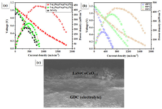
Figure 6.
(a) Electrochemical performances: characteristics curves of the utilization of our Sr in comparison with SrCoO3, La0.1Sr0.9Co0.9Ce0.1O3−δ and La0.2Sr0.8Co0.8Ce0.2O3−δ embedded on porous Ni-foam cathode in fuel cell operated at 550 °C; (b) fuel cell performance using our prepared La0.2Sr0.8Co0.8Ce0.2O3−δ embedded on porous Ni-foam cathode under different operating temperatures of 450–550 °C; (c) cross-sectional SEM images of tri-layer electrolyte supported fuel cell along with prepared La0.2Sr0.8Co0.8Ce0.2O3−δ embedded on porous Ni-foam cathode and GDC electrolyte examined after the electrochemical test.
3.4. Spectroscopic Analysis
Figure 7 shows the high-resolution XPS spectra for individual elements in La0.2Sr0.8Co0.8Ce0.2O3−δ, and after dispersing on the Ni-foam, where a change in the oxidation state of each element, such as Co, Ce, and O1s, can be observed after dispersing La0.2Sr0.8Co0.8Ce0.2O3−δ at Ni-foam substate. After subtracting Shirley’s background, high-resolution XPS spectra were fitted by a mixture of Lorentzian and Gaussian functions. The main task and aim are to study the chemical and electronic state configuration changes of Co-2p (Figure 7a), Ce-3d (Figure 7b), and O 1s (Figure 7c) spectra, respectively. Each element’s chemical state change can be observed after dispersing on Ni-foam, compared to pristine La0.2Sr0.8Co0.8Ce0.2O3−δ materials. The Co3+ and Co2+ peaks of Ni-foam-dispersed La0.2Sr0.8Co0.8Ce0.2O3−δ appear at 778.820/793.765 eV and 779.827/794.896 eV, whereas for La0.2Sr0.8Co0.8Ce0.2O3−δ powders, they are at 779.420/794.465 eV and 780.827/795.796 eV, as shown in Figure 7b [27], signifying a downshift of 0.5 ± 0.05 eV to lower binding energy (B.E). The Ni-foam-embedded La0.2Sr0.8Co0.8Ce0.2O3−δ sample exhibits more Co2+ states than that of La0.2Sr0.8Co0.8Ce0.2O3−δ. Figure 7b shows the XPS spectra of Ce-3d of the La0.2Sr0.8Co0.8Ce0.2O3−δ and La0.2Sr0.8Co0.8Ce0.2O3−δ samples after depositing on Ni-foam. The Ce4+ and Ce3+ peaks of the La0.2Sr0.8Co0.8Ce0.2O3−δ sample after depositing on Ni-foam appear at 881.82/900.65 eV and 898.45/915.72 eV, whereas for the pure La0.2Sr0.8Co0.8Ce0.2O3−δ sample, they are at 882.152/901.65 and 899.32/916.45 eV [16], showing a significant change in a binding energy shift up to about 0.6 ± 0.05 eV for the La0.2Sr0.8Co0.8Ce0.2O3−δ sample, to Ce-3d of the only La0.2Sr0.8Co0.8Ce0.2O3−δ sample. However, Co-2p (3/2, 1/2) shows a downshift in B.E while Ce-3d spectra shift up to exhibit more mixed valence states, which help to create additional oxygen vacancies by maintaining charge-neutrality due to the difference in the electronegativity after dispersing the La0.2Sr0.8Co0.8Ce0.2O3−δ sample on porous Ni-foam [27,28,29,30,31,32,33,34,35,36,37,38]. The O1s spectrum of the La0.2Sr0.8Co0.8Ce0.2O3−δ sample contains lattice oxygen (lattice O2−) and oxygen vacancy peaks. The O1s spectra of the La0.2Sr0.8Co0.8Ce0.2O3−δ sample after dispersing on Ni-foam cathode material display two partially superimposed peaks (Figure 7c). There are two major excitations: the first includes O1s of La0.2Sr0.8Co0.8Ce0.2O3−δ sample bands, and the second a La0.2Sr0.8Co0.8Ce0.2O3−δ sample, with Ni-foam bands with binding energy (BE) ranging from 528 to 533.5 eV. The low BE peak at 529.2 can be ascribed to the lattice oxygen (O Lattice), and the higher one at 531.4- to extra The high area percentage ratio of Olat/Ovac in the La0.2Sr0.8Co0.8Ce0.2O3−δ sample after dispersing on Ni-foam cathode indicates its high oxygen vacancy concentration and good oxygen adsorption capability, which plays an important role in high ORR activity [36,38]. However, different steps for the ORR mechanism in the La0.2Sr0.8Co0.8Ce0.2O3−δ sample with Ni-foam cathode are shown in Figure 8. All studies revealed that the prepared cathode is suitable in order to generate better ORR activity for energy application [39].
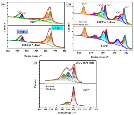
Figure 7.
X-ray photoelectron spectra of La0.2Sr0.8Co0.8Ce0.2O3−δ. Individual powders were embedded on porous Ni foam. (a) Co-2p, (b) Ce-3d, and (c) O1s spectra, respectively.
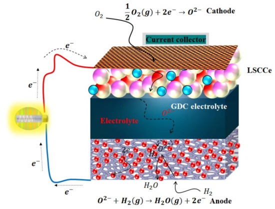
Figure 8.
Schematic diagram of the different steps for electrochemical processes from fuel, converting the fuel energy into electricity from La/Ce-doped SrCoO3-based cathode fuel cell over GDC electrolyte.
4. Conclusions
In conclusion, in this work, we have developed a semiconductor, SrCoO3, doped by both A-site and B-site using lanthanide and ceria, respectively. Later, La0.2Sr0.8Co0.8Ce0.2O3−δ particles were embedded on porous Ni-foam, and their electrochemical properties were studied. The prepared La0.2Sr0.8Co0.8Ce0.2O3−δ embedded on porous Ni-foam sample exhibits good ORR electrochemical performance at LTs, e.g., the maximum power density of 440 mW cm−2 achieved using cathode over GDC electrolyte at 550 °C. The excellent ORR electrocatalytic activity of La0.2Sr0.8Co0.8Ce0.2O3−δ embedded on porous Ni-foam can be attributed to a porous structure obtained by porous Ni-foam and the A- and B-site deficiency produced by La- and Ce-doping into SrCoO3.The mechanism for the high electrochemical performance of La0.2Sr0.8Co0.8Ce0.2O3−δ embedded on porous Ni-foam substrate is discussed in detail by different experimental approaches. The obtained results show that this approach could be useful not only in developing efficient ORR electrocatalysts, but could also be applied to other relevant applications.
Author Contributions
The conceptualization of this work was completed by J.W. (Jingping Wang), N.M. and M.A.K.Y.S.; J.W. (Jiaen Wu) and H.L. conducted the methodology; formal analysis and investigation by Y.L., Y.L. and P.W. provided the resources and data curation facilities. J.W. (Jingping Wang) completed the original draft preparation. Reviewed and edited by N.M., M.A.K.Y.S. and Y.L. All authors have read and agreed to the published version of the manuscript.
Funding
This work is supported by the Industry University Research Cooperation Project of Jiangsu 77g in China (Grant No. BY2021057), and the Qing Lan Project of Jiangsu Province. This work is also partly supported by the Jiangsu Province Higher Vocational College Young Teachers Enterprise Practice Training Funding Project (Grant No. 2021QYSJ048).
Data Availability Statement
The data supporting this study’s findings are available from the corresponding authors upon reasonable request.
Acknowledgments
The authors would like to acknowledge the School of Energy and Power Engineering, Nanjing Institute of Technology, Nanjing 211167, China for providing the funding to complete this work.
Conflicts of Interest
The authors declare no conflict of interest.
References
- Ormerod, R.M. Solid oxide fuel cells. Chem. Soc. Rev. 2003, 32, 17–28. [Google Scholar] [CrossRef] [PubMed]
- Jacobson, A.J. Materials for solid oxide fuel cells. Chem. Mater. 2010, 22, 660–674. [Google Scholar] [CrossRef]
- Pandey, A. Progress in solid oxide fuel cell (SOFC) research. JOM 2019, 71, 88–89. [Google Scholar] [CrossRef]
- Wachsman, E.D.; Lee, K.T. Lowering the temperature of solid oxide fuel cells. Science 2011, 334, 935–939. [Google Scholar] [CrossRef]
- Han, M.; Tang, X.; Yin, H.; Peng, S. Fabrication, microstructure and properties of a YSZ electrolyte for SOFCs. J. Power Sources 2007, 165, 757–763. [Google Scholar] [CrossRef]
- Leng, Y.; Chan, S.; Khor, K.; Jiang, S. Performance evaluation of anode-supported solid oxide fuel cells with thin film YSZ electrolyte. Int. J. Hydrogen Energy 2004, 29, 1025–1033. [Google Scholar] [CrossRef]
- Liu, Y.-L.; Hagen, A.; Barfod, R.; Chen, M.; Wang, H.-J.; Poulsen, F.W.; Hendriksen, P.V. Microstructural studies on degradation of interface between LSM–YSZ cathode and YSZ electrolyte in SOFCs. Solid State Ion. 2009, 180, 1298–1304. [Google Scholar] [CrossRef]
- Miao, L.; Hou, J.; Dong, K.; Liu, W. A strategy for improving the sinterability and electrochemical properties of ceria-based LT-SOFCs using bismuth oxide additive. Int. J. Hydrogen Energy 2019, 44, 5447–5453. [Google Scholar] [CrossRef]
- Danilov, N.; Lyagaeva, J.; Vdovin, G.; Medvedev, D.; Demin, A.; Tsiakaras, P. Electrochemical approach for analyzing electrolyte transport properties and their effect on protonic ceramic fuel cell performance. ACS Appl. Mater. Interfaces 2017, 9, 26874–26884. [Google Scholar] [CrossRef]
- Duan, C.; Kee, R.J.; Zhu, H.; Karakaya, C.; Chen, Y.; Ricote, S.; Jarry, A.; Crumlin, E.J.; Hook, D.; Braun, R. Highly durable, coking and sulfur tolerant, fuel-flexible protonic ceramic fuel cells. Nature 2018, 557, 217–222. [Google Scholar] [CrossRef]
- Choi, S.M.; An, H.; Yoon, K.J.; Kim, B.-K.; Lee, H.-W.; Son, J.-W.; Kim, H.; Shin, D.; Ji, H.-I.; Lee, J.-H. Electrochemical analysis of high-performance protonic ceramic fuel cells based on a columnar-structured thin electrolyte. Appl. Energy 2019, 233, 29–36. [Google Scholar] [CrossRef]
- An, H.; Lee, H.-W.; Kim, B.-K.; Son, J.-W.; Yoon, K.J.; Kim, H.; Shin, D.; Ji, H.-I.; Lee, J.-H. A 5 × 5 cm2 protonic ceramic fuel cell with a power density of 1.3 W cm–2 at 600 °C. Nat. Energy 2018, 3, 870–875. [Google Scholar] [CrossRef]
- Song, Y.; Chen, Y.; Wang, W.; Zhou, C.; Zhong, Y.; Yang, G.; Zhou, W.; Liu, M.; Shao, Z. Self-assembled triple-conducting nanocomposite as a superior protonic ceramic fuel cell cathode. Joule 2019, 3, 2842–2853. [Google Scholar] [CrossRef]
- Steele, B.C. Survey of materials selection for ceramic fuel cells II. Cathodes and anodes. Solid State Ion. 1996, 86, 1223–1234. [Google Scholar] [CrossRef]
- Rioja-Monllor, L.; Bernuy-Lopez, C.; Fontaine, M.-L.; Grande, T.; Einarsrud, M.-A. Processing of high-performance composite cathodes for protonic ceramic fuel cells by exsolution. J. Mater. Chem. A 2019, 7, 8609–8619. [Google Scholar] [CrossRef]
- Zhou, X.-D. Kill Two Problems with One Dual-Ion Cell. Joule 2019, 3, 2595–2597. [Google Scholar] [CrossRef]
- Choi, S.; Kucharczyk, C.J.; Liang, Y.; Zhang, X.; Takeuchi, I.; Ji, H.-I.; Haile, S.M. Exceptional power density and stability at intermediate temperatures in protonic ceramic fuel cells. Nat. Energy 2018, 3, 202–210. [Google Scholar] [CrossRef]
- Song, X.; Guo, W.; Guo, Y.; Mushtaq, N.; Shah, M.A.K.Y.; Irshad, M.S.; Lund, P.D.; Asghar, M.I. Nanocrystalline Surface Layer of WO3 for Enhanced Proton Transport during Fuel Cell Operation. Crystals 2021, 11, 1595. [Google Scholar] [CrossRef]
- Lu, Y.; Wang, J.; Mushtaq, N.; Shah, M.Y.; Irshad, S.; Rauf, S.; Motola, M.; Yan, S.; Zhu, B. Excellent oxygen reduction electrocatalytic activity of nanostructured CaFe2O4 particles embedded microporous Ni-Foam. Int. J. Hydrogen Energy 2022, 47, 10331–10340. [Google Scholar] [CrossRef]
- Zhou, X.; Hou, N.; Gan, T.; Fan, L.; Zhang, Y.; Li, J.; Gao, G.; Zhao, Y.; Li, Y. Enhanced oxygen reduction reaction activity of BaCe0. 2Fe0.8O3−δ cathode for proton-conducting solid oxide fuel cells via Pr-doping. J. Power Sources 2021, 495, 229776. [Google Scholar] [CrossRef]
- Tarutina, L.R.; Lyagaeva, J.G.; Farlenkov, A.S.; Vylkov, A.I.; Vdovin, G.K.; Murashkina, A.A.; Demin, A.K.; Medvedev, D.A. Doped (Nd, Ba) FeO3 oxides as potential electrodes for symmetrically designed protonic ceramic electrochemical cells. J. Solid State Electrochem. 2020, 24, 1453–1462. [Google Scholar] [CrossRef]
- Duan, C.; Tong, J.; Shang, M.; Nikodemski, S.; Sanders, M.; Ricote, S.; Almansoori, A.; O’Hayre, R. Readily processed protonic ceramic fuel cells with high performance at low temperatures. Science 2015, 349, 1321–1326. [Google Scholar] [CrossRef] [PubMed]
- Mushtaq, N.; Xia, C.; Dong, W.; Wang, B.; Raza, R.; Ali, A.; Afzal, M.; Zhu, B. Tuning the energy band structure at interfaces of the SrFe0.75Ti0.25O3−δ–Sm0.25Ce0. 75O2−δ heterostructure for fast ionic transport. ACS Appl. Mater. Interfaces 2019, 11, 38737–38745. [Google Scholar] [CrossRef] [PubMed]
- Kotomin, E.A.; Mastrikov, Y.A.; Merkle, R.; Maier, J. First principles calculations of oxygen reduction reaction at fuel cell cathodes. Curr. Opin. Electrochem. 2020, 19, 122–128. [Google Scholar] [CrossRef]
- Tatarchuk, T.; Bououdina, M.; Vijaya, J.J.; Kennedy, L.J. Spinel Ferrite Nanoparticles: Synthesis, crystal structure, properties, and perspective applications. In International Conference on Nanotechnology and Nanomaterials; Springer: Amsterdam, The Netherlands, 2016; pp. 305–325. [Google Scholar]
- Zuo, F.; Wang, L.; Wu, T.; Zhang, Z.; Borchardt, D.; Feng, P. Self-doped Ti3+ enhanced photocatalyst for hydrogen production under visible light. J. Am. Chem. Soc. 2010, 132, 11856–11857. [Google Scholar] [CrossRef]
- Mueller, D.N.; De Souza, R.A.; Yoo, H.-I.; Martin, M. Phase stability and oxygen nonstoichiometry of highly oxygen-deficient perovskite-type oxides: A case study of (Ba, Sr) (Co, Fe) O3−δ. Chem. Mater. 2012, 24, 269–274. [Google Scholar] [CrossRef]
- Liu, M.; Lynch, M.E.; Blinn, K.; Alamgir, F.M.; Choi, Y. Rational SOFC material design: New advances and tools. Mater. Today 2011, 14, 534–546. [Google Scholar] [CrossRef]
- Vøllestad, E.; Strandbakke, R.; Tarach, M.; Catalán-Martínez, D.; Fontaine, M.-L.; Beeaff, D.; Clark, D.R.; Serra, J.M.; Norby, T. Mixed proton and electron conducting double perovskite anodes for stable and efficient tubular proton ceramic electrolysers. Nat. Mater. 2019, 18, 752–759. [Google Scholar] [CrossRef]
- Campbell, C.T.; Peden, C.H. Oxygen vacancies and catalysis on ceria surfaces. Science 2005, 309, 713–714. [Google Scholar] [CrossRef]
- Patade, S.R.; Andhare, D.D.; Kharat, P.B.; Humbe, A.V.; Jadhav, K. Impact of crystallites on enhancement of bandgap of Mn1-xZnxFe2O4 (1≥ x≥ 0) nanospinels. Chem. Phys. Lett. 2020, 745, 137240. [Google Scholar] [CrossRef]
- Chen, M.; Paulson, S.; Kan, W.H.; Thangadurai, V.; Birss, V. Surface and bulk study of strontium-rich chromium ferrite oxide as a robust solid oxide fuel cell cathode. J. Mater. Chem. A 2015, 3, 22614–22626. [Google Scholar] [CrossRef]
- Mantzavinos, D.; Hartley, A.; Metcalfe, I.S.; Sahibzada, M. Oxygen stoichiometries in La1− xSrxCo1− yFeyO3− δ perovskites at reduced oxygen partial pressures. Solid State Ion. 2000, 134, 103–109. [Google Scholar] [CrossRef]
- Chandramohan, P.; Srinivasan, M.; Velmurugan, S.; Narasimhan, S. Cation distribution and particle size effect on Raman spectrum of CoFe2O4. J. Solid State Chem. 2011, 184, 89–96. [Google Scholar] [CrossRef]
- Singh, S.; Khare, N. Defects/strain influenced magnetic properties and inverse of surface spin canting effect in single domain CoFe2O4 nanoparticles. Appl. Surf. Sci. 2016, 364, 783–788. [Google Scholar] [CrossRef]
- Zhu, K.; Liu, H.; Li, X.; Li, Q.; Wang, J.; Zhu, X.; Yang, W. Oxygen evolution reaction over Fe site of BaZrxFe1-xO3−δ perovskite oxides. Electrochim. Acta 2017, 241, 433–439. [Google Scholar] [CrossRef]
- Wang, Z.; You, Y.; Yuan, J.; Yin, Y.-X.; Li, Y.-T.; Xin, S.; Zhang, D. Nickel-Doped La0. 8Sr0. 2Mn1−xNixO3 Nanoparticles Containing Abundant Oxygen Vacancies as an Optimized Bifunctional Catalyst for Oxygen Cathode in Rechargeable Lithium–Air Batteries. ACS Appl. Mater. Interfaces 2016, 8, 6520–6528. [Google Scholar] [CrossRef]
- Oh, N.K.; Kim, C.; Lee, J.; Kwon, O.; Choi, Y.; Jung, G.Y.; Lim, H.Y.; Kwak, S.K.; Kim, G.; Park, H. In-situ local phase-transitioned MoSe2 in La0.5Sr0.5CoO3−δ heterostructure and stable overall water electrolysis over 1000 hours. Nat. Commun. 2019, 10, 1723. [Google Scholar] [CrossRef]
- Baaloudj, O.; Kenfoud, H.; Badawi, A.K.; Assadi, A.A.; El Jery, A.; Assadi, A.A.; Amrane, A. Bismuth Sillenite Crystals as Recent Photocatalysts for Water Treatment and Energy Generation: A Critical Review. Catalysts 2022, 12, 500. [Google Scholar] [CrossRef]


Publisher’s Note: MDPI stays neutral with regard to jurisdictional claims in published maps and institutional affiliations. |
© 2022 by the authors. Licensee MDPI, Basel, Switzerland. This article is an open access article distributed under the terms and conditions of the Creative Commons Attribution (CC BY) license (https://creativecommons.org/licenses/by/4.0/).