Article

Combustion Synthesis of Metal-Intermetallic-Ceramic Laminate AlMg6-NiAl-TiC Composite

1
Merzhanov Institute of Structural Macrokinetics and Materials Science (ISMAN), Russian Academy of Sciences, 142432 Chernogolovka, Russia
2
Federal Research Center of Problems of Chemical Physics and Medicinal Chemistry of Russian Academy of Sciences, 142432 Chernogolovka, Russia
*
Author to whom correspondence should be addressed.
Crystals 2022, 12(12), 1851; https://doi.org/10.3390/cryst12121851
Submission received: 22 November 2022 / Revised: 14 December 2022 / Accepted: 16 December 2022 / Published: 19 December 2022
(This article belongs to the Section Hybrid and Composite Crystalline Materials)

Abstract

:
In this study, SHS was used to produce metal-intermetallic-ceramic laminate AlMg6-NiAl-TiC composite. The experiment conducted without a cylindrical powder pellet holder produced no joint between the NiAl and AlMg6 sheet. On the other hand, the experiment conducted inside a cylindrical powder pellet holder (CPPH) with a blind hole produced a joint. It was found that the AlMg6 sheet had a temperature of 400–550 °C across its entire thickness during SHS. The study of the microstructure and energy-dispersive analysis (EDS) of AlMg6-NiAl-TiC composite showed that it had five layers: (1) ceramic layer of 7-mm-thick TiC; (2) the upper diffusion layer that formed at the interface between NiAl and TiC consisted of TiC + NiAl; (3) an intermetallic layer, which consisted of 13-mm-thick NiAl; (4) the lower diffusion layer, which formed at the interface between NiAl and AlMg6; and (5) a layer of 4-mm-thick aluminum alloy AlMg6. The EDS showed that during the synthesis of NiAl and its interaction with the surface of the AlMg6 sheet, mixing of the components of the initial materials (NiAl, AlMg6) in the joint interface occurs. At the interface of NiAl and AlMg6, the microhardness was 790–870 HV, which indicates the presence of quenching structures in the melted zones.

1. Introduction

Intermetallic compounds (ICs) are compounds containing two or more metallic elements [1]. In recent years, ICs have drawn much interest due to their high melting point, low density, high oxidation resistance, etc. For example, the high performance properties of nickel-aluminum intermetallic compounds (NiAl) have resulted in them being widely used in the aerospace and automotive industries. The favorable properties of NiAl include a high corrosion resistance, low density, high melting point, high temperature strength, high temperature resistance, etc. These properties have allowed NiAl to be used as coating in gas turbines or high-temperature structural materials [2]. Additionally, the addition of titanium carbides and borides to NiAl increases its mechanical properties (such as hardness, wear resistance, elastic modulus, etc.) [3].
There are several methods of NiAl manufacturing such as casting, mechanical alloying [2,4], spark plasma sintering (SPS) [5], dynamic powder compaction (DPC) [6], and powder metallurgy [7]. Combustion synthesis (CS), which is a type of powder metallurgy, is a relatively rapid energy-efficient process of NiAl manufacturing, which does not require any special equipment [8,9]. CS can occur in two modes: the self-propagating high-temperature synthesis (SHS) [8] and the volume combustion synthesis (VCS), with the SHS mode being the preferable one due to its higher energy, reaction rate, higher purity of the reaction products, etc. [10]. However, in most cases, the SHS reaction products have relatively high porosity [11], which can be viewed as a considerable disadvantage in many fields [12]. High pressure applied to powder mixture can decrease the porosity [13,14]. On the other hand, the VCS mode is more suitable for weakly exothermic reactions, which require preheating before ignition, and is sometimes referred to as the thermal explosion mode [15].
The SHS mode involves the ignition of a Ni-Al powder mixture in ambient air or in an inert gas [15]. The size and shape of the initial powder particles, green density, and gas influence the way an SHS process occurs [8]. For example, the greater the particle size, the greater the probability that the reaction will be incomplete, and therefore ICs such as NiAl3, Ni2Al3, and NiAl can form, which leads to an inhomogeneous structure of the final product [16]. However, a subsequent heat treatment for 100 h at a temperature ranging from 850 to 1300 °C produces homogeneous NiAl with a relative density of 99% [6,17,18].
Currently, DPC processes are often used for NiAl manufacturing. DPC is a one-stage densification/bonding process that results in mechanical and chemical changes due to the unique physical phenomena produced by void closure (e.g., particle comminution, heterogeneous deformation, plastic flow, etc.). The compaction pressures applied to the powder are typically from a few to tens of GPa [6]. The pressure pulse is applied for a few microseconds. NiAl forms due to the densification between the powder particles and their plastic deformation. The surfaces of the powder particles melt, and chemical bonding is formed. There are two classes of chemical reactions that can occur in the powder mixture during DPC: thermally induced reactions or shock-induced reactions [19].
Unfortunately, the use of NiAl is limited by its poor normal temperature mechanical properties, particularly its low ductility and fracture toughness. Therefore, metal laminate composites (MLCs) have been used, which consist of a reinforcing element (e.g., fibers, cermet) and a ductile matrix material (e.g., steel, aluminum, titanium, etc.) [20,21,22,23]. Additionally, NiAl can be used as the reinforcing element in MLCs [24,25]. MLCs that have an intermetallic reinforcing element (including NiAl) are known as metal-intermetallic laminate (MIL) [26] composites. MIL composites are typically synthesized through hot pressing of alternating stacked metal foils so that intermetallic layers form in an interdiffusion and chemical reaction while sufficient pressure ensures the contact between the metal foils [27,28]. Additionally, to produce metal-intermetallic-ceramic laminate composites (which are layered materials based on NiAl and titanium carbide with a metal), an SHS process is conducted in a reactor under a pressure of 13 MPa in an atmosphere of argon [29]. Moreover, MIL composites can be produced through the SHS mode and explosive welding [30,31,32]. A common difficulty in the production of MIL composites is the significant differences in the physical and mechanical properties between the matrix material and the reinforcing element [21,23].
The purpose of this study was to examine the interface between an aluminum alloy AlMg6 sheet, a NiAl intermetallic compound, and TiC after SHS. In the present study, the AlMg6-NiAl-TiC laminate composite (MICl) formed due to the pressure exerted by the reaction gas products released during the synthesis process in a closed system (i.e., a constant-volume process), which is a novelty in the use of the SHS technique for manufacturing MICL. This method makes it possible to obtain MICLs in one technological stage without the use of expensive equipment, achieving a high energy efficiency in the process. Thus, this study is a new contribution to the field of MICL manufacturing.
The morphology and elemental distribution along the interface and in NiAl layer were studied through scanning electron microscope (SEM) and energy-dispersive spectroscopy (EDS).

2. Materials and Methods

Commercial Al powder ASD-1 (99.2% Al, Valkom-PM, Volgograd, Russia), Ni powder PNK-UT-3 (99.9% Ni, Metsintez, Tula, Russia), Ti powder PTS-1, and C powder P-803 were used as the precursors, which were weighted in stoichiometric proportions corresponding to NiAl and TiC. A sheet of aluminum alloy AlMg6 (4 × 15 × 15 mm) was used as a substrate (Table 1).
To fabricate the Ni-Al/Ti-C powder mixtures, the precursors were blended in a tumbling drum mixer for 3 h at 30 rpm with a ball-to-powder weight ratio of 5:1. The green powder mixtures were pressed in Ni-Al pellets by a manual hydraulic press (PRG-10, Lab Tools, St. Petersburg, Russia) for about 1 min under a pressure of approximately 240–250 MPa. The density of pressed Ni–Al pellets was determined from their geometric dimensions (micrometer by Dasqua, Cornegliano Laudense, Italy) and their weight (CAS XE-300 analytical balance, CAS, East Rutherford, NJ, USA). The relative density was 0.65.
To determine the possibility of obtaining the joint between the AlMg6 sheet and NiAl in the experiment conducted without a CPPH, the setup shown in Figure 1a was used. The setup consisted of a previously ground and degreased AlMg6 alloy sheet on which a tandem coaxially placed Ni-Al and Ti-C pellet was mounted. The ignition was induced by local heating of the Ti-C pellet surface with the formation of a combustion wave and its propagation throughout the height of the setup to the AlMg6 sheet.
To determine the effect of the SHS gas product pressure on the joint formation between AlMg6 and NiAl alloy, a setup of the isochoric SHS process was developed (Figure 1b). The setup consisted of a cylindrical powder pellet holder (CPPH) with a blind hole with a 10 mm diameter and 2 mm wall thickness, tandemly arranged pellets of Ni-Al and Ti-C, and AlMg6 sheet. Holes were made in the rim of CPPH to attach the ignitor and thermocouples. CPPH, which contained Ti-C and Ni-Al pellets, was pressed closely against the AlMg6 sheet to ensure a tight setup. Thermocouples were placed on the upper and lower parts of the sheet and on the upper part of the Ni-Al pellet to determine the maximum sheet heating temperature from the exothermic reaction.
The metallographic specimens were prepared using a metallographic grinding and polishing machine (ShLIF-1M/V) and diamond paste. The study of the microstructure and EDS analysis were performed using a Zeiss SUPRA 25 (Germany) scanning auto-emission electron microscope and an “Inca Energy” EDX, OXFORD instruments (RESOL. AT 5.9 keV–133 eV. Complete scan of 0–20 keV). The mapping and chemical element distribution were obtained at an accelerating voltage of 15 keV. In the case of a bulk sample, the EDX signal output area is ~1–5 μm depending on the accelerating voltage and material density. The X-ray diffraction (XRD) analysis was carried out using a DRON-3M diffractometer. The samples were scanned using Cu-K radiation, 20 to 80 (2Θ), with a scanning step of 0.02 and exposure time of 1 s. In this study, microhardness (HV) was measured using a PMT-3 Vickers hardness tester. Loads of 100 g were applied for 15 s. The signals from the thermocouples were recorded with a frequency of 250 Hz through a QMBox analog-to-digital converter—ADC (R-Technology, Moscow, Russia).

3. Results

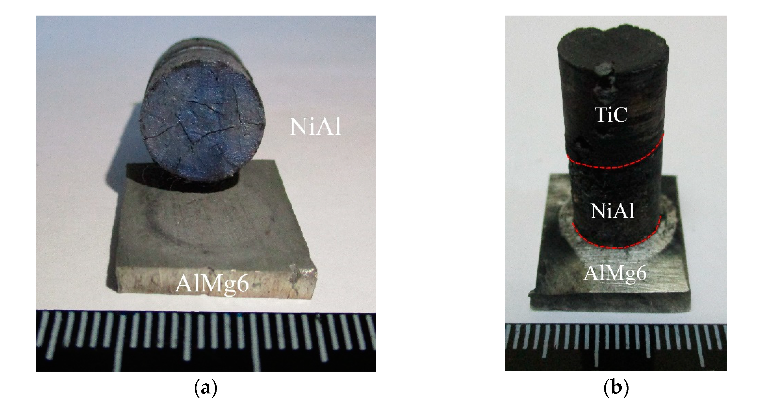
It was found that the setup shown in Figure 1a did not produce a joint between NiAl and AlMg6 as shown in Figure 2a. Moreover, this assembly did not always initiate combustion in the Ni-Al pellet.
Figure 2b shows the metal-intermetallic-ceramic laminate (MICL) AlMg6-NiAl-TiC composite, which was produced by SHS using CPPH as shown in Figure 1b.
Figure 3 shows combustion thermograms that indicate that the combustion temperature of NiAl was about 1500–1600 °C. The AlMg6 sheet in the spot of the contact with the NiAl pellet had the same temperature (the red and black curves). The blue curve shows a rapid cooling of the AlMg6 sheet. At the lower part of the AlMg6 sheet, the temperature was 400 °C. The NiAl combustion rate was calculated to be 13 mm/s.
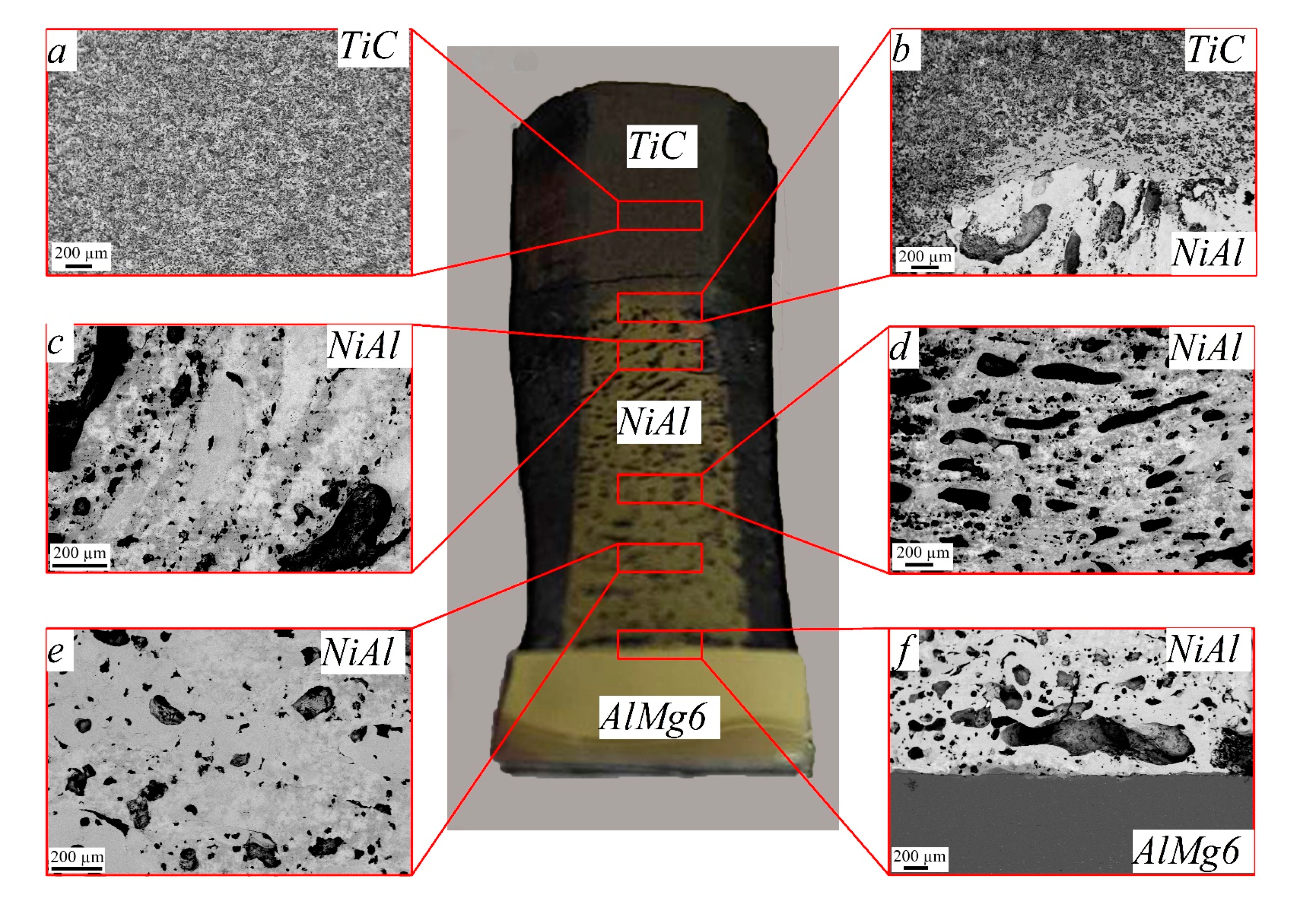
The metal-intermetallic-ceramic laminate AlMg6-NiAl-TiC composite obtained in the experiments consisted of the following layers (Figure 4):
  • Ceramic layer of 7-mm-thick TiC (Figure 4a);
  • An upper diffusion layer, which formed at the interface between NiAl and TiC (Figure 4b) and consisted of TiC + NiAl;
  • An intermetallic layer, which consisted of 13-mm-thick NiAl (Figure 4c–e);
  • A lower diffusion layer, which formed at the interface between NiAl and AlMg6 (Figure 4f);
  • A layer of 4-mm-thick aluminum alloy AlMg6 (Figure 4f).
The pores in the upper part of the intermetallic layer were at an angle of 40° relative to the reaction propagation front (Figure 4b,c). The grains of NiAl had an elongated shape and had the same angle as the pores. In the remaining part of the intermetallic layer, the pores were parallel to the direction of the reaction propagation front (Figure 4d). The size and number of pores decreased starting at a distance of 8 mm from the initial point of NiAl synthesis and the pores also became more rounded, with diameters ranging from 50 to 100 µm (Figure 4e). The shape of the NiAl grains also changed: they became equiaxed throughout (Figure 4e,f).
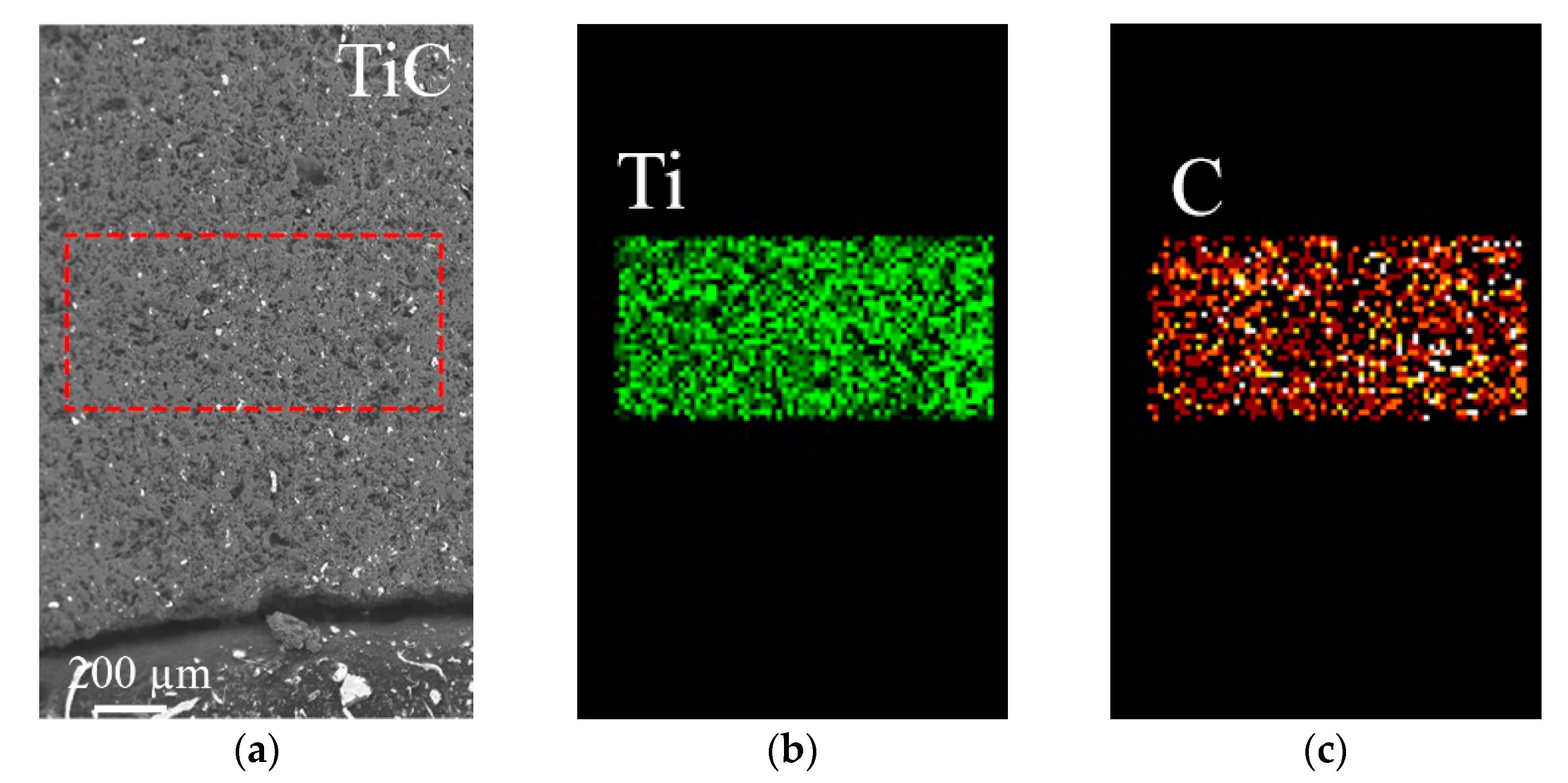
Figure 5a shows the SEM image of the ceramic layer that resulted from the Ti-C pellet SHS. This layer had a uniform component distribution (Figure 5b,c) and consisted of brittle TiC. MICL grinding and polishing resulted in a crack in TiC, which occurred just above the TiC-NiAl joint interface.
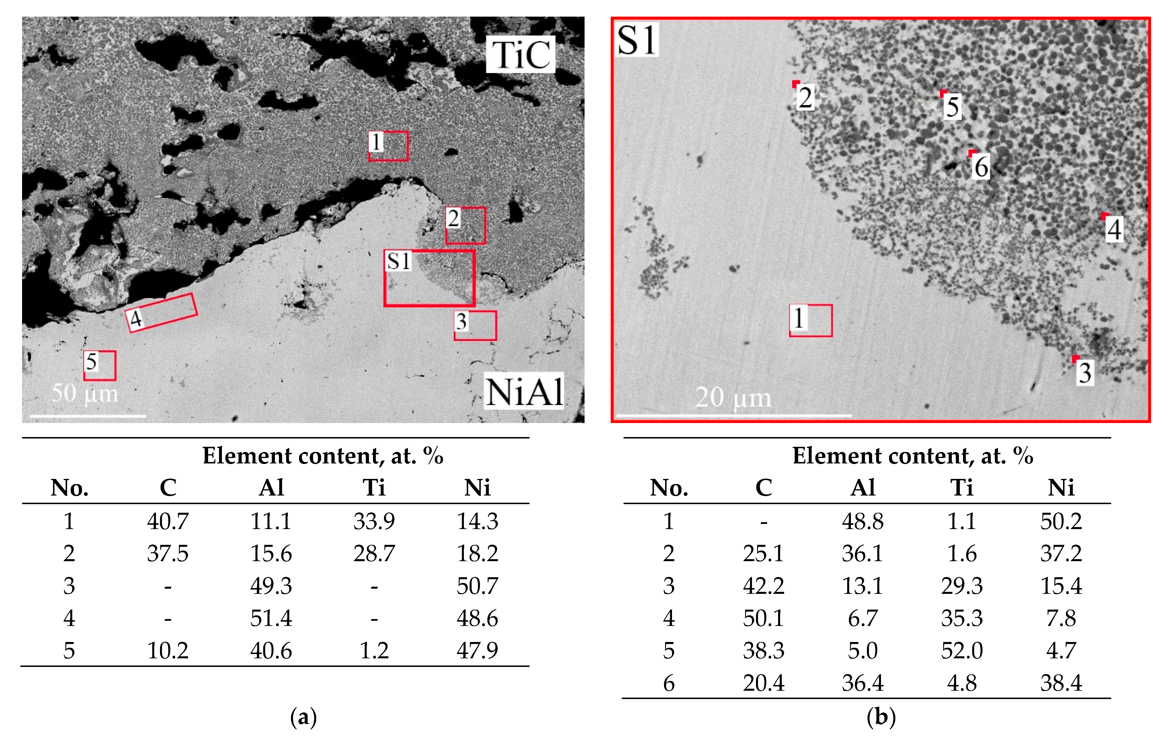
The diffusion layer that formed at the interface of NiAl and TiC (Figure 6a) had a gradient structure due to the diffusion of Ni and Al into TiC to a depth of about 500 µm. An intermixed zone up to 30 µm thick consisting of NiAl and finely dispersed TiC was also found (Figure 6b).
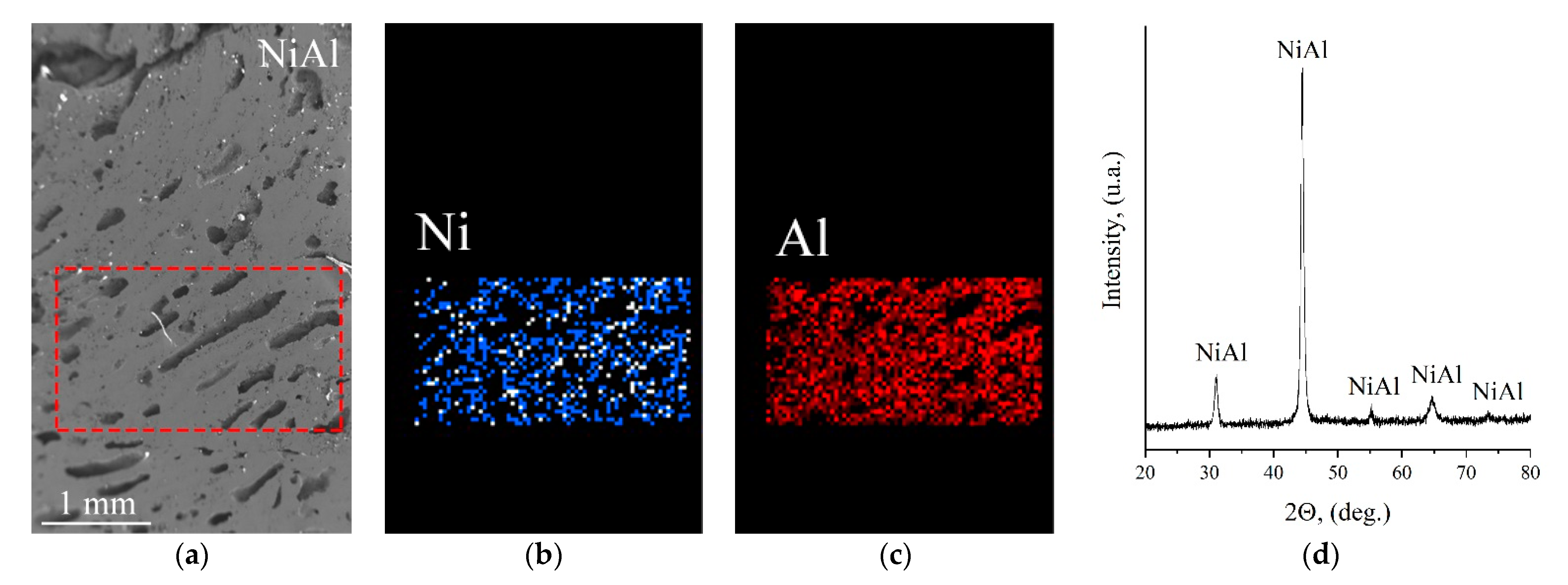
The intermetallic layer consisting of NiAl is a porous material (Figure 7) in which the pores generally have an elongated form with a length of 150–300 µm and a width of 30–100 µm. As a result of NiAl synthesis, a uniform distribution of Ni and Al was observed throughout the intermetallic layer (Figure 7b,c). The XRD results showed that this NiAl has a single-phase NiAl composition (Figure 7d).
Figure 8 shows the joint interface of NiAl with AlMg6. The pores in NiAl are located along the joint interface. The white inclusions in the intermetallic structure are abrasive particles (Al2O3) that were introduced into the sample during grinding and polishing.
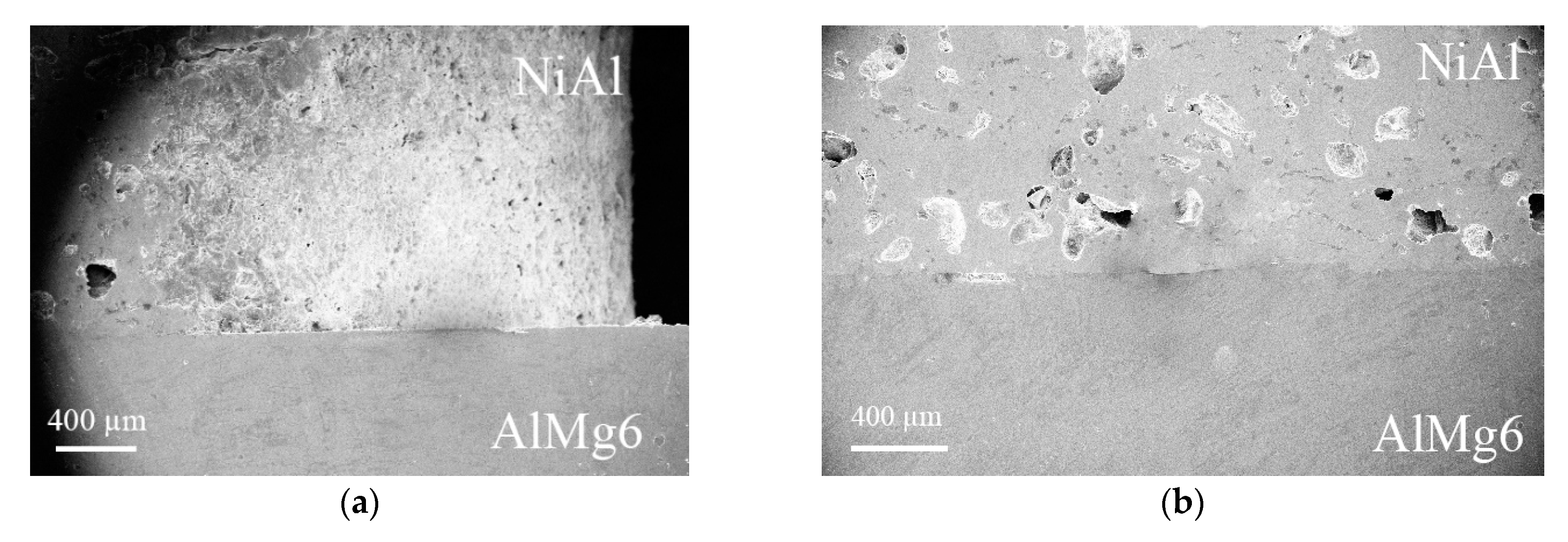
The joint interface between AlMg6 and NiAl had a straight-line appearance (Figure 9) with local diffusion layers (Figure 10). The NiAl structure had irregularly shaped pores and close to spherical ones (Figure 9b).
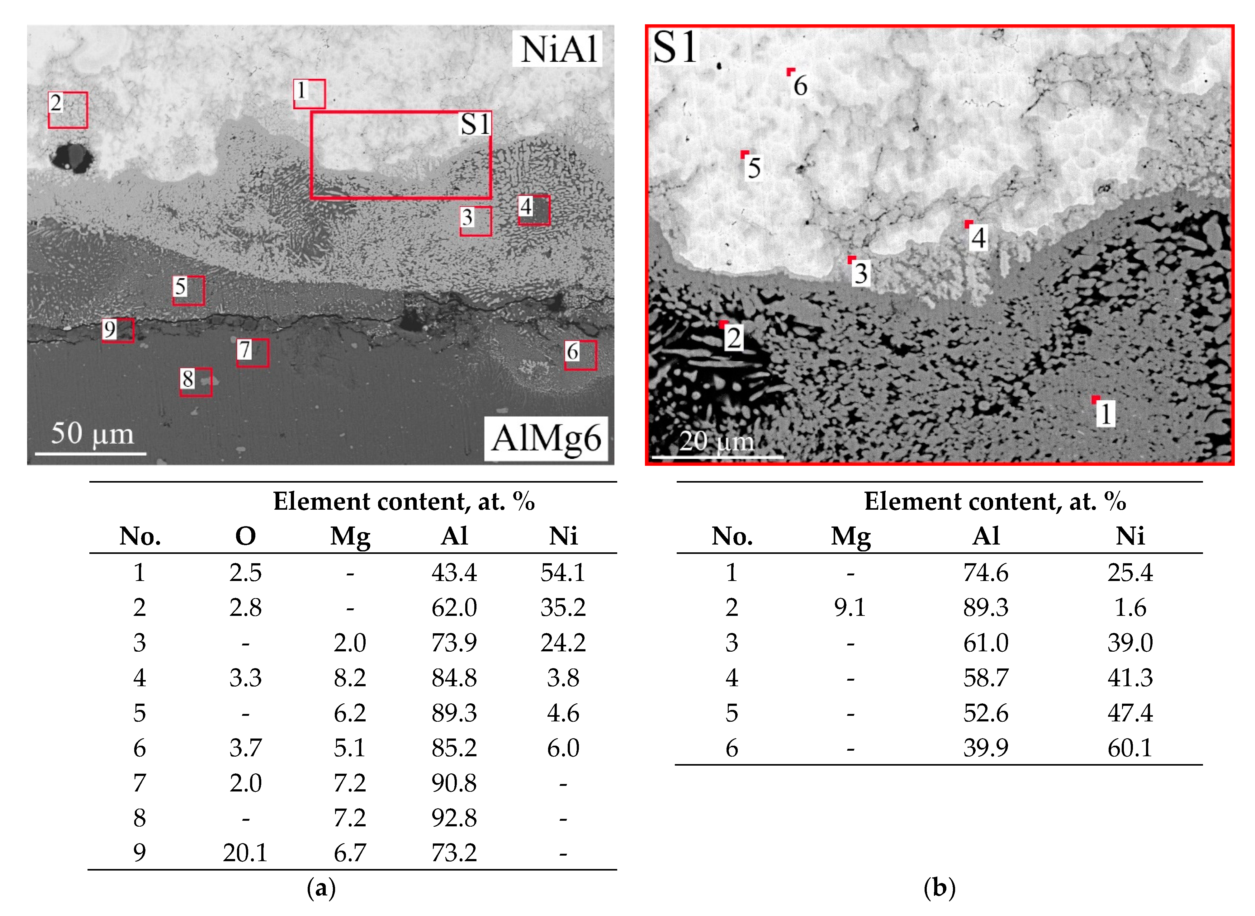
The diffusion layer formed in the NiAl intermetallic joint interface with a 10- to 100-µm-thick AlMg6 sheet and a gradient structure (Figure 10a), which consisted of a NiAl3 needle-like structure in an AlMg6 matrix (Figure 10b). AlMg6 did not undergo structural changes and phase transformations along the thickness.
Figure 11 shows the microhardness distribution in the NiAl-AlMg6 joint interface.

4. Discussion

The results showed that the pressure of the released gas products during the synthesis of TiC and NiAl in the experiments according to the setup shown in Figure 1a formed a gas gap between the pellets TiC and NiAl and between NiAl and AlMg6. This gas gap resulted in the disruption of the contact between the AlMg6 and NiAl surfaces, loss of heat transfer, and breaking of the resulting bonds between the contacted surfaces. As a result, the joint between NiAl and AlMg6 could not be obtained (Figure 2a).
In order to eliminate the formation of the gas gap at the TiC-NiAl and NiAl-AlMg6 contact interfaces and create a high internal pressure during the SHS process of the materials, the setup shown in Figure 1b with CPPH was applied. As a result of the experiments according to this setup, a layered gradient material TiC + NiAl + AlMg6 was obtained (Figure 2b). Thus, it was shown that the formation of the joint between Ni-Al and AlMg6, in addition to the temperature released during the SHS process, is influenced by the pressure of the gas products inside CPPH to create a strong contact between the surfaces to be joined.
As a result of the mixing of the components of the initial materials, TiC ↔ NiAl compound TiC + NiAl was formed. The structure of the TiC-NiAl joint interface was in the form of distributed globular TiC grains, sized from 0.3 to 2 µm in the NiAl matrix. The structure was ordered in the mixing zone, with the largest TiC grains closer to the titanium carbide layer and the smallest grains closer to NiAl (Figure 4b).
The NiAl + AlMg6 joint interface is formed by diffusion processes during the melting of the AlMg6 surface under the effect of SHS.
According to the results of the EDS analysis, it was found that during the synthesis of NiAl and its interaction with the surface of the AlMg6 sheet, there was mixing of the components of the initial materials (NiAl, AlMg6) in the joint interface (Figure 9a). It was shown that the NiAl-AlMg6 joint interface has local melted zones up to 100 µm wide. The formation of multidirectional needle grains of NiAl3 in the AlMg6 matrix in the melted zone between NiAl and AlMg6 (Figure 9b) is associated with the saturation of the melt with diffused aluminum from the AlMg6 layer formed in the process of SHS and rapid cooling of the liquid phase. The rapid cooling of the liquid phase of NiAl3 and AlMg6 caused the formation of quenching structures (differently directed needle grains NiAl3) in the melted zone. The depth of AlMg6 melting as a result of the NiAl SHS heat flux was about 40 µm.
At distances up to 100 µm from the mixing zone, the intermetallic compound consisted of the NiAl phase with Ni3Al phases along its joint interface and at distances over 100 µm from the mixing zone, the intermetallic compound consisted of the NiAl phase.
The AlMg6 microhardness was uniform throughout the thickness and was 110–120 HV. In the melted zone at the interface of the NiAl intermetallic compound with AlMg6, the microhardness was 790–870 HV, which confirms the formation of quenching structures in the melted zones.

5. Conclusions

The metal-intermetallic-ceramic laminate (MICL) AlMg6-NiAl-TiC composite was successfully synthesized through an SHS process.
The gas products released in the process led to the disruption of the contact between Ti-C, Ni-Al, and the AlMg6 sheet, which broke the formed bonds between the joined materials and the rupture of the joint. Thus, it was impossible to obtain the joint between NiAl and the AlMg6 sheet without using the cylindrical powder pellet holder (CPPH).
As a result of the experiments carried out to obtain a metal intermetallic ceramic laminate (MICL) AlMg6-NiAl-TiC composite, it was found that for the formation of a compound between NiAl and AlMg6, in addition to the heat emitted during SHS, the pressure of its own gases produced during SHS is also necessary.
Thus, the developed method of obtaining the intermetallic compound/cermet layer on a metallic base can be used in conditions of a constant-volume process (isochoric process), without the use of complex (expensive) equipment. The use of a constant-volume process (isochoric process) provides a closed system during SHS, which makes it possible to use the pressure of the reaction gas products to create a joint between the layers in MICL.
This study is the initial stage in producing MICL by SHS in conditions of a constant-volume process using a cylindrical powder pellet holder (CPPH). Further experiments are planned to be carried out in a special air-tight reactor, which will allow an increase in the size of MICL and the use of different ambient gases.

Author Contributions

Conceptualization, A.M. and I.D.; methodology, A.M. and I.D.; software, D.S.; validation, A.M., I.D. and D.S.; formal analysis, I.D.; investigation, S.S.; resources, D.S.; data curation, I.D.; writing—original draft preparation, I.D. and A.M.; writing—review and editing, I.D., D.S., and A.M.; visualization, S.S.; supervision, I.D., D.S. and A.M.; project administration, D.S. and A.M.; funding acquisition, A.M. and D.S. All authors have read and agreed to the published version of the manuscript.

Funding

This research was supported by The Ministry of Science and Higher Education of the Russian Federation (Agreement with Joint Institute for High Temperatures RAS No. 075-15-2020-785 dated 23 September 2020).

Institutional Review Board Statement

Not applicable.

Informed Consent Statement

Not applicable.

Data Availability Statement

Not applicable.

Conflicts of Interest

The authors declare no conflict of interest.

References

  1. Levashov, E.A.; Mukasyan, A.S.; Rogachev, A.S.; Shtansky, D.V. Self-propagating high-temperature synthesis of advanced materials and coatings. Int. Mater. Rev. 2017, 62, 203–239. [Google Scholar] [CrossRef]
  2. Bochenek, K.; Basista, M. Advances in processing of NiAl intermetallic alloys and composites for high temperature aerospace applications. Prog. Aerosp. Sci. 2015, 79, 136–146. [Google Scholar] [CrossRef]
  3. Fan, X.; Huang, W.; Zhou, X.; Zou, B. Preparation and characterization of NiAl–TiC–TiB2 intermetallic matrix composite coatings by atmospheric plasma spraying of SHS powders. Ceram. Int. 2020, 46, 10512–10520. [Google Scholar] [CrossRef]
  4. Hyjek, P.; Sulima, I.; Malczewski, P.; Bryła, K.; Jaworska, L. Effect of Reactive SPS on the Microstructure and Properties of a Dual-Phase Ni-Al Intermetallic Compound and Ni-Al-TiB2 Composite. Materials 2020, 13, 5668. [Google Scholar] [CrossRef]
  5. Nosewicz, S.; Jurczak, G.; Wejrzanowski, T.; HajIbrahim, S.; Grabias, A.; Węglewski, W.; Kaszyca, K.; Rojek, J.; Chmielewski, M. Thermal conductivity analysis of porous NiAl materials manufactured by spark plasma sintering: Experimental studies and modelling. Int. J. Heat Mass Transfer 2022, 194, 123070. [Google Scholar] [CrossRef]
  6. Eakins, D.E.; Thadhani, N.N. Shock compression of reactive powder mixtures. Int. Mater. Rev. 2009, 54, 181–213. [Google Scholar] [CrossRef] [Green Version]
  7. Ning, H.; Wang, D.; Zhao, J.; Wang, B.; Liu, G. Fabrication and joining of NiAl and TiAl intermetallics by additive sintering. Mater. Sci. Eng. A 2022, 849, 143439. [Google Scholar] [CrossRef]
  8. Sytschev, A.E.; Vrel, D.; Boyarchenko, O.D.; Roshchupkin, D.V.; Sachkova, N.V. Combustion synthesis in bi-layered (Ti−Al)/(Ni−Al) system. J. Mater. Process. Technol. 2017, 240, 60–67. [Google Scholar] [CrossRef]
  9. Aruna, S.T.; Mukasyan, A.S. Combustion Synthesis and Nanomaterials. Curr. Opin. Solid State Mater. Sci. 2008, 12, 44–50. [Google Scholar] [CrossRef]
  10. Rosa, R.; Veronesi, P.; Leonelli, C. 4—Use of combustion synthesis/self-propagating high- temperature synthesis (SHS) for the joining of similar/dissimilar materials. In Joining Processes for Dissimilar and Advanced Materials; Rakesh, P., Davim, J.P., Eds.; Woodhead Publishing: Sawston, UK, 2022; pp. 63–79. [Google Scholar] [CrossRef]
  11. Bazhin, P.M.; Konstantinov, A.S.; Chizhikov, A.P.; Pazniak, A.I.; Kostitsyna, E.V.; Prokopets, A.D.; Stolin, A.M. Laminated cermet composite materials: The main production methods, structural features and properties (review). Ceram. Int. 2021, 47, 1513–1525. [Google Scholar] [CrossRef]
  12. Lee, H.; Ikenaga, A.; Kim, S.H.; Kim, K.B. The effects of induction heating rate on properties of Ni-Al based intermetallic compound layer coated on ductile cast iron by combustion synthesis. Intermetallics 2007, 15, 1050–1056. [Google Scholar] [CrossRef]
  13. Cai, X.; Li, K.; Sang, C.; Ren, X.; Leihu, X.; Feng, P. Interfacial microstructure and mechanical properties of Ti/Cu joint manufactured by Ni-Al thermal explosion reaction. J. Manuf. Mater. Process. 2020, 57, 919–929. [Google Scholar] [CrossRef]
  14. Cai, X.; Ren, X.; Sang, C.; Zhu, L.; Li, P.Z.; Feng, Z. Dissimilar joining mechanism, microstructure and properties of Ni to 316 stainless steel via Ni-Al thermal explosion reaction. Mater. Sci. Eng. 2021, 807, 140868. [Google Scholar] [CrossRef]
  15. Thiers, L.; Mukasyan, A.S.; Varma, A. Thermal explosion in Ni-Al system: Influence of reaction medium microstructure. Combust. Flame 2002, 131, 198–209. [Google Scholar] [CrossRef]
  16. Herbold, E.B.; Jordan, J.L.; Thadhani, N.N. Effects of processing and powder size on microstructure and reactivity in arrested reactive milled Al + Ni. Acta Mater. 2011, 59, 6717–6728. [Google Scholar] [CrossRef] [Green Version]
  17. Wang, B.; Wang, D.; Zhao, J.; Ning, H.; Liu, G. Deformation behavior and fracture mechanism of a novel laminated Ni/Al sheets during in-situ tensile process. Mater. Sci. Eng. A 2021, 827, 142050. [Google Scholar] [CrossRef]
  18. Ozdemir, O.; Zeytin, S.; Bindal, C. Tribological properties of NiAl produced by pressure-assisted combustion synthesis. Wear 2008, 265, 979–985. [Google Scholar] [CrossRef]
  19. Church, P.; Claridge, R.; Ottley, P.; Lewtas, I.; Harrison, N.; Gould, P.; Braithwaite, C.; Williamson, D. Investigation of a Nickel-Aluminum Reactive Shaped Charge Liner. J. Appl. Mech. 2013, 80, 031701324234. [Google Scholar] [CrossRef]
  20. Han, Y.; Cheng, R.; Lin, C.; Wang, E.; Wang, Y.; Song, L.; Han, W. Fabrication and characterization of NiTif-SiCf synergistically reinforced (Al3Ti+Al3Ni)-based metallic-intermetallic laminated composite. J. Alloys Compd. 2021, 881, 160520. [Google Scholar] [CrossRef]
  21. Liang, G.; Yuan, M.; Wang, H.; Pei, X.; Zhou, X.; Li, D. Microstructure evolution and mechanical properties of Ti-Ni-Al ternary Metallic-Intermetallic Laminate (MIL) composites. J. Alloys Compd. 2023, 935, 167853. [Google Scholar] [CrossRef]
  22. Hou, C.; Zhang, S.; Ma, Z.; Lu, B.; Wang, Z. Effects of SiC Fibers and Laminated Structure on Mechanical Properties of Ti–Al Laminated Composites. Materials 2021, 14, 1323. [Google Scholar] [CrossRef]
  23. Zelepugin, S.A.; Shkoda, O.A.; Lepakova, O.K.; Zelepugin, A.S.; Kasatskii, N.G.; Shavnev, A.A.; Krasnov, E.I. Synthesis of the Ti–TiAl3 metallic-intermetallic laminate composite by various methods. Trudy VIAM 2016, 47, 23–31. [Google Scholar] [CrossRef]
  24. Konieczny, M. Mechanical properties and deformation behavior of laminated Ni-(Ni2Al3+NiAl3) and Ni-(Ni3Al+NiAl) composites. Mater. Sci. Eng. 2013, 586, 11–18. [Google Scholar] [CrossRef]
  25. Han, Y.; Jiang, F.; Lin, C.; Yuan, D.; Huang, H.; Wang, E.; Wang, Z.; Guo, C. Microstructure and mechanical properties of continuous ceramic SiC and shape memory alloy NiTi hybrid fibers reinforced Ti-Al metal-intermetallic laminated composite. J. Alloys Compd. 2017, 729, 1145–1155. [Google Scholar] [CrossRef]
  26. Emurlaeva, Y.Y.; Ivanov, I.V.; Lazurenko, D.V.; Ogneva, T.S.; Chen, P.W.; Zhou, Q.; Bataev, A.A.; Ruktuev, A.A.; Tanaka, S.; Bataev, I.A. On the texture and superstructure formation in Ti-TiAl3-Al MIL composites. Intermetallics 2021, 135, 107231. [Google Scholar] [CrossRef]
  27. Ogneva, T.S.; Bataev, I.A.; Mali, V.I.; Anisimov, A.G.; Lazurenko, D.V.; Popelyukh, A.I.; Emurlaeva, Y.Y.; Bataev, A.A.; Tanaka, S.; Yegoshin, K.D. Effect of sintering pressure and temperature on structure and properties of Ni single bond Al metal-intermetallic composites produced by SPS. Mater. Charact. 2021, 180, 11415. [Google Scholar] [CrossRef]
  28. Srivastava, V.C.; Singh, T.; Chowdhury, S.G.; Jindal, V. Microstructural Characteristics of Accumulative Roll-Bonded Ni-Al-Based Metal-Intermetallic Laminate Composite. J. Mater. Eng. Perform. 2012, 21, 1912–1918. [Google Scholar] [CrossRef]
  29. Riyadi, T.W.B.; Mujiyono, M.; Nurhadiyanto, D.; Mukhammad, A.F.H.; Hassan, S.B.A.; Wulandari, A.P.; Murni, M. Fabrication of NiAl and TiC intermetallic matrix composite coatings. Compos. Interfaces 2021, 29, 328–343. [Google Scholar] [CrossRef]
  30. Malakhov, A.; Shakhray, D.; Denisov, I.; Galiev, F.; Seropyan, S. Synthesis of NiAl Intermetallic Compound under Shock-Wave Extrusion. Materials 2022, 15, 6062. [Google Scholar] [CrossRef]
  31. Kim, Y.K.; Pouraliakbar, H.; Hong, S.I. Effect of interfacial intermetallic compounds evolution on the mechanical response and fracture of layered Ti/Cu/Ti clad materials. Mater. Sci. Eng. A 2020, 772, 138802. [Google Scholar] [CrossRef]
  32. Pouraliakbar, H.; Khalaj, G.; Jandaghi, M.R.; Fadaei, A.; Ghareh-Shiran, M.K.; Shim, S.H.; Hong, S.I. Three-layered SS321/AA1050/AA5083 explosive welds: Effect of PWHT on the interface evolution and its mechanical strength. Int. J. Press. Vessel. Pip. 2020, 188, 104216. [Google Scholar] [CrossRef]
Figure 1. Experimental setups: (a) the experiment conducted without a CPPH; (b): with Ni-Al and Ti-C pellets located in CPPH: 1—ignitor, 2—Ti-C pellet, 3—Ni-Al pellet, 4—AlMg6 sheet, 5—CPPH, 6—thermocouples.
Crystals 12 01851 g001
Figure 2. Photograph of the specimens after SHS: (a) the experiment conducted without a CPPH; (b): with Ni-Al and Ti-C pellets located in CPPH.
Crystals 12 01851 g002
Figure 3. Thermograms of the combustion temperature of NiAl and heating of AlMg6 sheet during SHS.
Crystals 12 01851 g003
Figure 4. Microstructure of the MICL TiC + NiAl + AlMg6 composite: (a) TiC layer; (b) joint interface between NiAl and TiC; (ce) NiAl layer with different pore shapes; (f) joint interface between NiAl and AlMg6.
Crystals 12 01851 g004
Figure 5. SEM image of the ceramic layer (a) and (b,c) EDS analysis maps showing the distribution of Ti and C, respectively. The red square is scan area.
Crystals 12 01851 g005
Figure 6. SEM image of the NiAl-TiC interface and the results of EDS analysis: (a) joint interface and (b) intermixed zone.
Crystals 12 01851 g006
Figure 7. SEM image of intermetallic layer (a) and EDS analysis maps showing the distribution of Ni (c) and Al (b) XRD pattern of NiAl (d). The red square is scan area.
Crystals 12 01851 g007
Figure 8. SEM image of NiAl-AlMg6 interface (a) and (b–d) EDS analysis maps showing the distribution of Ni, Al, and Mg.
Crystals 12 01851 g008
Figure 9. Interface of AlMg6 + NiAl: (a) edge view; (b) center view.
Crystals 12 01851 g009
Figure 10. SEM image of AlMg6-NiAl interface and the results of EDS analysis: (a) joint interface; (b) diffusion layer.
Crystals 12 01851 g010
Figure 11. Microhardness distribution in the NiAl-AlMg6 joint interface.
Crystals 12 01851 g011
Table 1. Composition of green pellets and size of powder particles.
PelletPowderParticle Size, µm
to 50% wt.to 90% wt.
Ni-AlNi<9.1<21.0
Al<18.4<28.2
Ti-CTi<52.5<85.4
C<2.5<4.0
Publisher’s Note: MDPI stays neutral with regard to jurisdictional claims in published maps and institutional affiliations.