Article

Synergistic Effect of Hexagonal Boron Nitride-Coated Separators and Multi-Walled Carbon Nanotube Anodes for Thermally Stable Lithium-Ion Batteries

1
Department of Physics, College of Science, King Faisal University, P.O. Box 400, Al-Ahsa 31982, Saudi Arabia
2
Department of Physics, School of Engineering, University of Petroleum & Energy Studies, Dehradun 248007, India
3
Physics Department, Faculty of Science, Assiut University, Assiut 71516, Egypt
4
Chemistry Department, McGill University, 801 Sherbrooke St. W, Montreal, QC H3A 0B8, Canada
5
National Nanotechnology Center, King Abdulaziz City for Science and Technology, P.O. Box 6086, Riyadh 11442, Saudi Arabia
*
Author to whom correspondence should be addressed.
Crystals 2022, 12(2), 125; https://doi.org/10.3390/cryst12020125
Submission received: 5 December 2021 / Revised: 9 January 2022 / Accepted: 14 January 2022 / Published: 18 January 2022
(This article belongs to the Section Inorganic Crystalline Materials)

Abstract

:
In this work, we report the development of separators coated with hexagonal boron nitride (hBN) to improve the thermal stability of Li-ion batteries (LIBs). Aiming to achieve a synergistic effect of separators and anodes on thermal stability and electrochemical performance, multiwalled carbon nanotubes (MWCNTs) were prepared via plasma-enhanced chemical vapor deposition (PECVD) method and used as potential anode materials for LIBs. The grown MWCNTs were well characterized by using various techniques which confirmed the formation of MWCNTs. The prepared MWCNTs showed a crystalline structure and smooth surface with a diameter of ~9–12 nm and a length of ~10 μm, respectively. Raman spectra showed the characteristic peaks of MWCNTs and BN, and the sharpness of the peaks showed the highly crystalline nature of the grown MWCNTs. The electrochemical studies were performed on the fabricated coin cell with a MWCNT anode using a pristine and BN-coated separators. The results show that the cell with the BN-coated separator in a conventional organic carbonate-based electrolyte and MWCNTs as the anode resulted in a discharge capacity (at 65 °C) of ~567 mAhg−1 at a current density of 100 mAg−1 for the first cycle, and delivered a capacity of ~471 mAhg−1 for 200 cycles. The columbic efficiency was found to be higher (~84%), which showed excellent reversible charge–discharge behavior as compared with the pristine separator (69%) after 200 cycles. The improved thermal performance of the LIBs with the BN-coated separator and MWCNT anode might be due to the greater homogeneous thermal distribution resulting from the BN coating, and the additional electron pathway provided by the MWCNTs. Thus, the fabricated cell showed promising results in achieving the stable operation of the LIBs even at higher temperatures, which will open a pathway to solve the practical concerns over the use of LIBs at higher temperatures without compromising the performance.

1. Introduction

Due to their extended life cycle and high energy density, lithium-ion batteries (LIBs) are proven to be a standard source of energy for portable electronic devices. However, the applications of LIBs are hindered because of the crucial challenge of their operation even at mildly elevated temperatures (≈60–80 °C) [1,2,3,4,5,6,7]. Thus, thermal stability is very important for energy storage devices, especially for flexible devices [8,9,10]. In LIBs, the transport of lithium ions occurs between the anode and cathode via an ionically conductive electrolyte. An electrically insulating separator composed of a thin polymeric film is a key component of LIBs, which acts as a physical barrier between the two electrodes by preventing electrical contact. The separator, which is not electrically insulating, allows ion transport during charge and discharge via pathways for ionic conduction throughout an interconnected porous structure [11,12]. The performance of LIBs at high temperatures results in the failure of the separator and electrolyte; furthermore, the separator can soften or shrink with the heating, thus resulting in electrical short circuit [2,3]. Therefore, to achieve the safety standards for widely used electronic devices, the development of a safe battery with stable temperature technologies is highly desired [13,14]. The development of safe and reliable devices capable of working at temperatures over 60 °C would be useful for several applications [1,7,15]. To overcome the challenges associated with LIBs operation at high temperature and with the aim of improving the performance and safety of separators, tremendous efforts have been made [16]. The intrinsic hydrophobicity of commercial separators (polyolefins) has been modified by attaching hydrophilic monomers or functional groups on the surface of the membrane, which resulted in the improved hydrophilicity for the efficient wetting of electrolytes [17,18,19]. In other work, the improvement in the electrolyte wettability and thermal stability was achieved by the coating of ceramic particles, including SiO2 or Al2O3, on the surface of polyolefin membranes [20,21,22]. However, the requirement of organic binders to prepare these ceramic particle coatings still limits the maximum safe operating temperature while also lowering membrane porosity.
More recently, due to its high thermal conductivity, chemical inertness, and mechanical robustness, hexagonal boron nitride (hBN), which is an electrically insulating isomorph of graphene, has attracted huge interest as a ceramic filler [23]. Moreover, hBN has also been coated on the surface of commercial polymer separators to increase the stability of lithium metal anodes [24]. Graphite is commonly used for the anodes in current LIBs; however, it exhibits a low specific capacity of 372 mAhg−1, which significantly limits the energy density of LIBs. Therefore, significant effort has been focused on developing anodes with a high specific capacity. In contrast to graphite, carbon nanotubes (CNTs) exhibit specific capacities of 300–1000 mAhg−1, depending on their morphological characteristics [25,26,27,28]. It is well known that Li-ions can intercalate into both the channel between the nanotubes as well as the interior of the nanotubes themselves [27]. However, the performance of CNT-based anodes in LIBs could be improved further by introducing defects into CNTs and producing randomly oriented, “spaghetti-like” CNTs. Defects created in CNTs can reduce the energy barrier and facilitate Li+ diffusion into the inner core of the CNTs as well as their adsorption on the walls [29], while, spaghetti-like CNTs could enhance the charge storage capacity due to the large surface area of the nanotubes [28].
In recent years, many studies have focused on the growth of CNTs. Among different CNT growth approaches, CVD is one of the most used techniques [30]. Typically, CNTs are grown through the plasma-enhanced chemical vapor deposition (PECVD) method in which metal catalyst particles or islands are deposited on the top of semiconducting or insulating oxides such as silicon oxide [31,32].
In this work, we demonstrate the fabrication of a LIBs system based on a BN-coated polypropylene separator and MWCNTs as the anode. MWCNTs were directly grown on the Si/SiO2 substrate using PECVD method with Ni catalysts and Cr as a barrier layer between the catalyst and substrate. The electrochemical performance of the as-grown CNT-based anode with a BN-coated separator was evaluated in a coin cell by means of charge–discharge cycles and electrochemical impedance spectroscopy (EIS) measurements. The results were compared with the LIBs fabricated with a pristine separator. The fabricated battery shows an excellent electrochemical performance, including enhanced cyclability, and thermal stability (65 °C) in comparison to the pristine separator. The fabricated LIBs will open up the possibility to produce a safe, rechargeable LIBs technology with the capability to operate at elevated temperatures.

2. Experimental Details

2.1. Growth of the MWCNTs

For the growth of the MWCNTs, a Si/SiO2 substrate was used in the present experiment. Prior to growth, the substrate was cleaned by deionized water (DI water), followed by ethanol, and drying in air. The substrate was placed in a DC-sputtering system and ~25 nm of a Ni catalyst layer was deposited on its surface. In addition, a Cr layer of ~5 nm, an electrically conductive thin barrier layer between the substrates and the Ni catalyst layer, was deposited. After this step, the growth of the MWCNTs was achieved by using plasma enhanced chemical vapor deposition (PECVD) in an EasyTube 3000 (FirstNano; South Technology Drive, Central Islip, NY, USA) system. At the end of the growth period, the samples were slowly cooled, within the furnace, under a H2 gas environment. The MWCNTs obtained were carefully scratched from the substrate and, after characterization, were used as the anode for the fabrication of LIBs.

2.2. Materials Characterization

The structural properties of the samples were obtained by using an X-ray diffractometer (Philips X’Pert; MPD 3040, EA Almelo, The Netherlands) that was equipped with Cu Kα radiations in the 2θ range of 10–70°. The grown product was studied by using field emission scanning electron microscopy (FESEM; JEOL, JSM-7600F, Tokyo, Japan) and transmission electron microscopy (TEM; JEOL, JEM 2100 F, Tokyo, Japan) operated at 200 kV. Room-temperature Raman spectroscopy was carried out by using a confocal Raman microscope (LabRAM, HR800, Longjumeau, France SAS) in an ambient atmosphere with a He–Ne wavelength laser of 633 nm and a power of 20 mW.

2.3. Cell Fabrication and Electrochemical Characterization

2.3.1. MWCNT-Based Anode Preparation

A MWCNT anode was prepared by mixing the as-obtained product, carbon black (carbon super P, MTI), and polyvinylidene fluoride or polyvinylidene difluoride (PVDF, Sigma Aldrich, Burlington, MA, United States, MW ~534,000) with a ratio of 8:1:1, respectively. Then, the slurry was casted onto a copper foil with help of a doctor blade and dried at 80 °C overnight. Lithium foil (Sigma Aldrich, Burlington, MA, United States, thickness 0.75 mm, width 45 mm, 99.9% trace metal basis) was used as a counter electrode, with a polypropylene membrane (25 μm, Celgard 2325) separator and 1 M lithium hexafluoro phosphate (LiPF6) dissolved in ethylene carbonate (EC) and dimethyl carbonate (DMC) (1:1 in vol%) (all from Sigma Aldrich, Burlington, MA, United States, 99.9%) as the electrolyte. The coin cells (2032-type) were assembled in a glovebox at room temperature. Galvanostatic charge–discharge and cycling experiments were performed using a multi-channel battery tester (LAND) with a potential range between 0.0 and 2.8 V at a current density of 100 mAg−1. An aging time of 12 h was used before starting the battery cycling. A Biologic SP-300 potentiostat was used to perform electrochemical impedance spectroscopies (EIS) between 200 kHz and 100 mHz using a sinusoidal perturbation at the amplitude of 10 mV. Cyclic voltammetry tests were carried out in a potential range of 0.0 to 3.0 V with a scan rate of 0.5 mV s−1. A schematic diagram as shown in Figure 1 represents the growth of MWCNTs on the Si/SiO2 substrate and the fabrication of LIBs using a MWCNT anode and BN-coated separator.

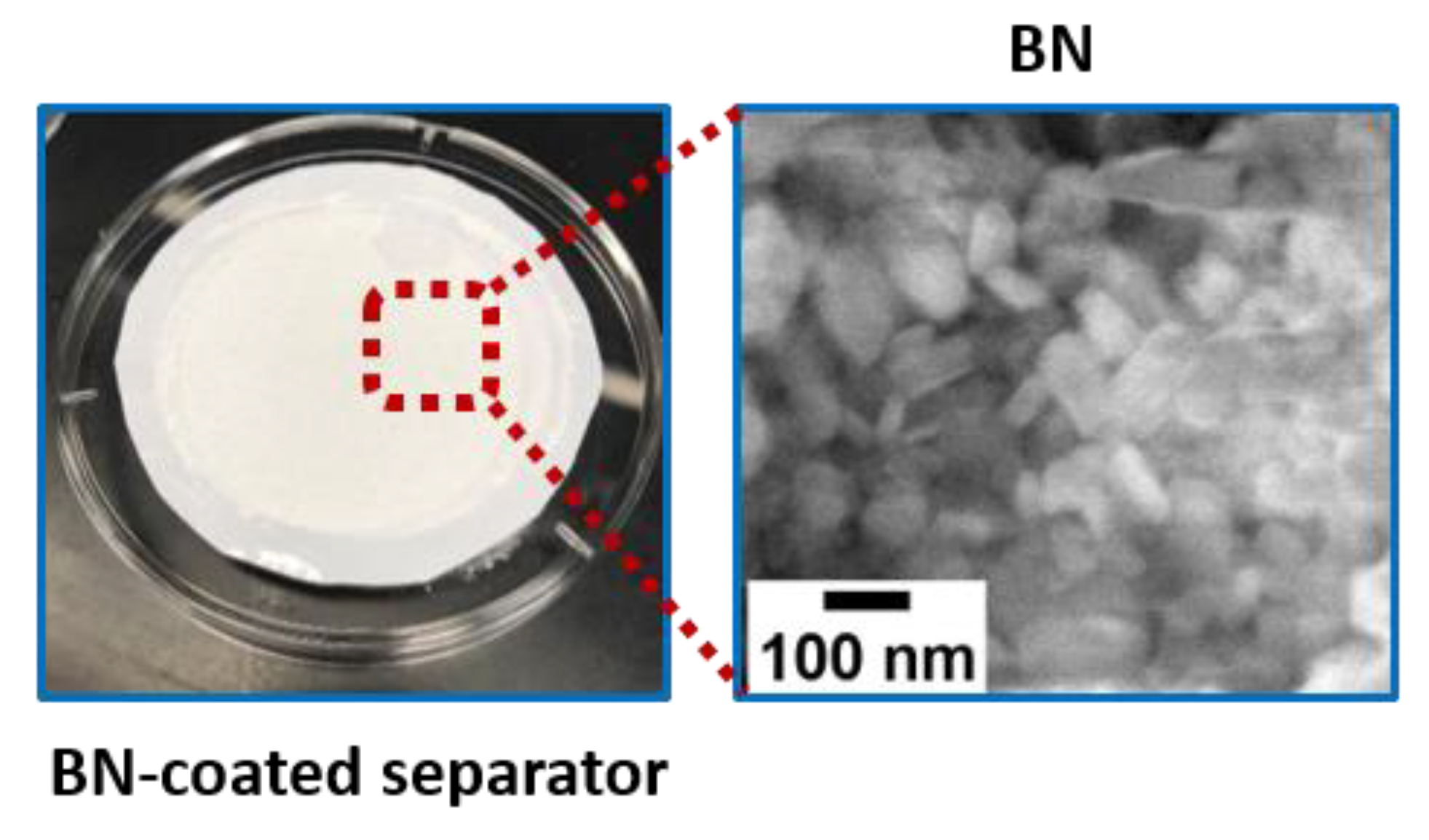
2.3.2. Preparation of the BN-Coated Separator

The BN-coated separator was prepared by adding 3 mg of BN powder (99.3%; Supervac, New Delhi, India), a-DMP4/10 mL DMF, and a few drops of PVDF dissolved in NMP. The mixture was sonicated for 1 h at a 50% amplitude (Vibracell, Sonics & Materials Inc., Newtown, CT, USA) and using a vacuum filter to get a thin BN-coated polypropylene separator. Figure 2 shows the preparation of the BN-coated separator.

3. Results and Discussion

Structural studies of the MWCNTs were carried out by using XRD analysis. Figure 3 shows the XRD patterns of the MWCNTs grown on the Si/SiO2 substrate by using the PECVD method. It can be clearly seen from the XRD pattern that the diffraction peaks positioned at a 2θ of 25.22° correspond to the (002) plane of graphene sheets, and the peaks at the 2θ of 43.30° related to the (100) plane correspond to graphitic structures [33]. Within the detection limit of XRD, no other phase was detected, indicating the successful growth of MWCNTs. Generally, the intensity of the (002) diffraction peak of CNTs provides the information related to the number of walls in the CNTs. With the increase in the number of walls, the intensity of the (002) peak increases due to the enhancement in the contribution of the intratube structure [34]. In this work, the much lower intensity of the (002) peak of the MWCNTs and broader FWHM could be considerably related to the thinner wall, which might lead to the formation of CNTs with few walls.
Further structural information including the degree of crystallinity and disordering of the as-grown MWCNTs was obtained by using Raman spectroscopy analysis. The presence/absence of defects inside the CNTs could be observed qualitatively in the Raman spectra. Figure 4a shows the Raman spectrum of the MWCNTs measured at room temperature in the wavenumber range of 100–3000 cm−1 through a He–Ne laser with a wavelength of 633 nm. In the Raman spectrum shown in Figure 4a, three modes were observed at wavenumbers 1329.26 cm−1, 1578.09 cm−1, and 2648.96 cm−1, which were assigned to D, G, and G’ bands, respectively [35]. The origin of these characteristic modes could be explained by the D band or the disorder peak, which arises due to dangling sp2 bonds on the sidewalls of CNTs; the G band or the order peak, which originates due to pristine carbon atoms that form CNTs; and the G′ band, which provides the information related to the presence of long-range order within the CNTs [36]. Additionally, the existence of long-range ordered crystalline graphite promotes the charge storage capacity. The intensity ratios (ID/IG) of D and G peaks provides the information on the “purity” of the CNTs. More specifically, purity refers to the degree of crystallinity in the CNTs; a higher the degree of graphitic crystallinity results in a lower intensity ratio and less defects [36]. From the Raman spectrum shown in Figure 4a, we observed a ratio (ID/IG) of 1.96 for the CNTs grown on the Si/SiO2 substrate, which indicates the formation of defect-induced CNTs [37]. The intensity ratio of IG’/IG offers vital information about the number of layers [38,39,40]. If the ratio of the G’/G band is 2, then it is a single-layer structure; if ratio is between 1 and 2, then it is a bilayer or double-layer structure; and if the ratio is within 1 > 0.5 > 0, then it is a multilayer or double-layer structure. We observed the ratio of IG′/IG = 0.35, which indicates the multilayer formation of CNTs. It was reported [41] that a higher G′/G peak ratio ascribed to the superior “average purity” of the CNTs. The ratio of IG′/IG = 0.35 for the MWCNTs indicates that they possessed a better purity which would be advantageous for charge storage applications. Figure 4b depicts the Raman spectrum of the hBN powder that was used for coating on the separator. In the Raman spectrum of BN, a single peak positioned at 1367 cm−1 was observed corresponding to the E2g vibration mode of hBN [42].
The morphology and structure of the as-grown CNTs were studied by using FESEM and TEM analyses. Figure 5a shows the FESEM micrographs of the MWCNTs grown on the Si/SiO2 substrate. Figure 5a demonstrates the tubular morphology of the CNTs resulting from the formation of closely spaced and relatively large bundles of entangling nanotubes. These CNTs are porous in nature and possessed a dense arrangement all over the surface. Additionally, the CNTs are curvy, lengthy, and reveal a spaghetti-like structure with a length of ~10 μm and diameter of ~9.6–11.8 nm, respectively. Generally, the microstructure and morphology of CNTs affect the charge storage capacity. Thus, the spaghetti-like porous structure of the CNTs will possibly be best suited for LIBs as it could enhance the charge storage capacity due to the large surface area of the nanotubes [28]. Figure 5b depicts the morphology of BN powder, where agglomerated particles with diameters ranging from 80 to 150 nm can be seen.
The additional morphological features of CNTs were determined through TEM measurements. A TEM micrograph of the MWCNTs is shown in Figure 5c, which demonstrates that the CNTs were multi-walled nanotubes with a diameter ranging from 9 to 12 nm and having a hollow core. The atomic structure of the MWCNTs was characterized by high-resolution transmission electron microscopy (HRTEM). The HRTEM image shown in the inset of Figure 5c reveals that the MWCNTs were crystalline in nature with a lattice spacing of about 3.42 Å, corresponding to the distance between the (002) planes in the CNTs.
The electrochemical performances of the LIBs with the pristine and the BN-coated separator are shown in Figure 6. The galvanostatic charge–discharge curves for the first cycle of the fabricated battery with the CNT anode were obtained in the voltage range of 0.0 to 2.8 V with a current density of 100 mAg−1 at 65 °C. It can be clearly seen from Figure 6a that the cell with the pristine separator delivered a discharge capacity of 468 mAhg−1 and a charge capacity of 412 mAhg−1, respectively. On the other hand, the cell with the BN-coated separator resulted in an increase of the discharge and charge capacities to 567 mAhg−1 and 422 mAhg−1, respectively, at the same conditions. This enhancement in the capacities might be attributed to the better utilization of active materials favoring the promoting electron as well as the reduction of Li dendrites by the BN coating.
For practical applications, the rate capability performance of an anode material for the fabricated cell is one of the most important parameters [43]. To evaluate the fabricated cells for their rate capability performance, all the cells were subjected to current densities ranging from 100 to 300 mAg−1 with an identical discharge and charge current density and 10 charge/discharge cycles at each current density. The results depicted in Figure 6b show that at a current density of 100 mAg−1, the cell with a BN-coated separator possesses a noticeably higher capacity than the cell with the pristine separator. As the current density was increased from 100 to 200 mAg−1, the capacity of the BN-coated separator cell declined from 567 to 375 mAhg−1, while for the cell with the pristine separator, a decrease in capacity from 468 to 329 mAhg−1 was observed. Upon a further increase in current density to 300 mAg−1, a further capacity decrease to 223 mAhg−1 for the BN-coated separator cell and 180 mAhg−1 for the cell with the pristine separator, respectively, were recorded. When returned to 100 mAg−1 after cycling at 300 mAg−1, both the cells retained their capacities agreeably and remained stable for the next 10 cycles. It is worth mentioning that the cell with the BN-coated separator showed a remarkable improvement in rate performance compared with the cell with the pristine separator. CNTs and their nanocomposite-based anodes have been studied previously, including at even higher current densities; however, the achievable discharge capacity remained in the range of 50–200 mAhg−1 at room temperature [44,45,46]. In this work, at 65 °C, stable discharge capacities of 567 mAhg−1 at 100 mAg−1, 375 mAhg−1 at 200 mAg−1, and 223 mAhg−1 at 300 mAg−1, respectively, were obtained for the cell fabricated with the MWCNT anode and BN-coated separator. These capacities demonstrate that the MWCNT anode with a BN-coated separator contributed significantly to the enhanced electrochemical performance and thermal stability of the LIBs in comparison to other MWCNT-based anodes [43,44,45,46].
The cycling performance of the cell with the pristine separator and BN-coated separator, respectively, was evaluated at 100 mAg−1 as shown in Figure 6c. It can be observed that the discharge capacity gradually decreased in the initial several cycles for both the cells with the pristine and BN-coated separator, respectively. The BN-coated separator-based cell achieved a stable capacity of around ~510 mAhg−1 in the 30th cycle, while the cell with the pristine separator showed a continuous decrease even in the initial 50 cycles. It can be seen that after 200 cycles, the MWCNT anode with the pristine separator showed a discharge capacity of ~321 mAhg−1. In comparison, when the BN-coated separator was placed in the cell, the MWCNTs anode exhibited a higher discharge capacity of ~472 mAhg−1. The enhanced cycling performances of the cell with the MWCNTs anode and BN-coated separator were mainly attributed to the synergistic advantages of the carbon nanotubes and the BN layer: (1) the carbon nanotube anode, being conductive in nature, provides an additional electron path which facilitates a high electrochemical reversibility with high discharge capacities and (2) the BN layer provides a thermal barrier and facilitates a stable electrochemical reaction [24]. These two synergistic contributions effectively control the thermal stability of the fabricated cell and improved the electrochemical performance. Furthermore, the coulombic efficiency dropped to 69% after 200 cycles in the cell with the pristine separator. In comparison, a much more stable coulombic efficiency of ~84% after 200 cycles was maintained with the BN-coated separator even at a high temperature of 65 °C. These results show that the cycling performance of the MCNTs anode at a high current density of 100 mAg−1 was significantly improved using the BN-coated separator in comparison to the previous reports of CNT-based anodes and pristine separators [44,45,46].
In order to evaluate the redox potentials of reversible systems, cyclic voltammetry (CV) is a valuable electrochemical technique. CV studies of the cell electrode using the pristine separator and BN-coated separator, respectively, were performed using a potential window of 0.0 to 3.0 V vs. Li/Li+ as shown in Figure 6d. The CV results show no significant change in the redox potentials of the pristine or BN-coated separators, but differences in the magnitude of the cathodic and anodic peak currents were certainly observed. A higher amplitude in the current was observed for the cell with the BN-coated separator, indicating a higher redox activity. It is evident from the CV curves that there is no pronounced peak in the range of 1.0 to 3.0 V, while broad peaks were recorded in the voltage range of 0.1–0.7 V, which could be attributed to the electrochemical processes related to MWCNTs [47].
In order to study the kinetics and interfacial behaviors of the electrodes while using pristine and BN-coated separators, electrochemical impedance spectroscopy (EIS) measurements were performed as shown in Figure 6e. The EIS spectra of the LIBs with the pristine separator and BN-coated separator are compared in Figure 6e. An ohmic resistance between the electrode and the electrolyte [48] could be estimated from the intersection of the X-axis and the semicircle as depicted in Figure 6e. It was observed that the ohmic resistance of the MWCNTs anode with the pristine separator resulted in a value of 20.92 Ω; however, the BN-coated separator had a lower value of 9.81 Ω. Furthermore, the diameters of the semicircles, which corresponds to the charge transfer resistance, were affected by the modification in the separator. The MWCNTs anode with the BN-coated separator showed a smaller polarization resistance of 446.4 Ω as compared to the MWCNTs anode with the pristine separator (475.9 Ω). In earlier reports, the values of charge transfer resistance have been reported to range from 50 to 800 Ω, depending on the CNTs’ morphological characteristics [25,49]. Thus, in this work, the results obtained from EIS are in good agreement with these earlier reports. It could be suggested that the enhancement in the surface reaction kinetics was attributed to the higher conductivity of the MWCNTs and good stability of the electrode due to the BN layer, which facilitates a stable electrochemical reaction.

4. Conclusions

In summary, we have fabricated LIBs with a MWCNTs anode and BN-coated separator and improved the electrochemical performance and thermal stability of the cell. MWCNTs were grown directly on the Si/SiO2 substrate by using the PECVD method. XRD, Raman, FESEM, and HRTEM studies showed the successful formation of MWCNTs with a crystalline nature and high purity. Raman spectroscopy measurements revealed that the grown MWCNTs possessed characteristic D, G, and G’ bands, and the ratio of IG′/IG = 0.35 indicated the formation of multilayer CNTs. The electrochemical studies were evaluated at 65 °C on the fabricated cells using a MWCNTs anode with a BN-coated separator and pristine separator, respectively. The results showed that with the use of a BN-coated separator and MWCNTs anode, a discharge capacity of ~567 mAhg−1 at 100 mAg−1 was obtained and a capacity of ~471 mAhg−1 was retained after 200 cycles. However, the use of a MWCNTs anode and pristine separator resulted in a discharge ~468 mAhg−1 at 100 mAg−1, which dropped to ~321 mAhg−1 after 200 cycles. Furthermore, using the BN-coated separator, the coulombic efficiency was maintained at 84% after 200 cycles at a current density of 100 mAg−1, while the coulombic efficiency decreased rapidly to 69% using a pristine separator at the same conditions. The coating of hBN on the separator in combination with the MWCNTs anode enhanced the cycling stability of the LIBs as compared to those with a pristine separator. Moreover, with the improved thermal stability of the BN-coated separators, the operation of the LIBs at a higher temperature could be attained. The improved electrochemical performance of the fabricated LIBs with a MWCNTs anode and BN-coated separator might be due to an additional electron pathway provided by the MWCNTs and a uniform thermal distribution of the separator resulting from the BN coating layer. Thus, the fabricated cell showed promising results in achieving the stable operation of the LIBs even at a high temperature, which opens a pathway to solve the practical concerns over the use of LIBs at higher temperatures without compromising the performance.

Author Contributions

Conceptualization, F.A.; data curation, F.A. and S.R.; formal analysis, S.K., N.M.S. and O.S.; funding acquisition, F.A.; methodology, F.A. and S.R.; resources, F.A., S.R. and A.A.; visualization, H.A. and M.A.; writing—original draft, F.A.; writing—review and editing, S.K., N.M.S., O.S., S.R., A.A., H.A. and M.A. All authors have read and agreed to the published version of the manuscript.

Funding

Deanship of Scientific Research at King Faisal University under the Nasher Track (Grant No. 216057).

Institutional Review Board Statement

Not applicable.

Informed Consent Statement

Not applicable.

Data Availability Statement

Data are available upon reasonable request.

Acknowledgments

This work was funded by the Deanship of Scientific Research at King Faisal University under the Nasher Track (Grant No. 216057).

Conflicts of Interest

The authors declare no conflict of interest.

References

  1. Hu, Q.; Osswald, S.; Daniel, R.; Zhu, Y.; Wesel, S.; Ortiz, L.; Sadoway, D.R. Graft copolymer-based lithium-ion battery for high-temperature operation. J. Power Sources 2011, 196, 5604–5610. [Google Scholar] [CrossRef] [Green Version]
  2. Jiang, W.; Liu, Z.; Kong, Q.; Yao, J.; Zhang, C.; Han, P.; Cui, G. A high temperature operating nanofibrous polyimide separator in Li-ion battery. Solid State Ion. 2013, 232, 44–48. [Google Scholar] [CrossRef]
  3. Lee, H.; Yanilmaz, M.; Toprakci, O.; Fu, K.; Zhang, X. A review of recent developments in membrane separators for rechargeable lithium-ion batteries. Energy Environ. Sci. 2014, 7, 3857–3886. [Google Scholar] [CrossRef]
  4. Shim, J.; Kostecki, R.; Richardson, T.; Song, X.; Striebel, K.A. Electrochemical analysis for cycle performance and capacity fading of a lithium-ion battery cycled at elevated temperature. J. Power Sources 2002, 112, 222–230. [Google Scholar] [CrossRef]
  5. Kang, J.; Rizzoni, G. Study of relationship between temperature and thermal energy, operating conditions as well as environmental factors in large-scale lithium-ion batteries. Int. J. Energy Res. 2014, 38, 1994–2002. [Google Scholar] [CrossRef]
  6. Zhang, S.S.; Xu, K.; Jow, T.R. LiBOB-based gel electrolyte Li-ion battery for high temperature operation. J. Power Sources 2006, 154, 276–280. [Google Scholar] [CrossRef]
  7. Bodenes, L.; Naturel, R.; Martinez, H.; Dedryvère, R.; Menetrier, M.; Croguennec, L.; Pérès, J.-P.; Tessier, C.; Fischer, F. Lithium secondary batteries working at very high temperature: Capacity fade and understanding of aging mechanisms. J. Power Sources 2013, 236, 265–275. [Google Scholar] [CrossRef]
  8. Zhao, Z.; Xia, K.; Hou, Y.; Zhang, Q.; Ye, Z.; Lu, J. Designing flexible, smart and self-sustainable supercapacitors for portable/wearable electronics: From conductive polymers. Chem. Soc. Rev. 2021, 50, 12702–12743. [Google Scholar] [CrossRef]
  9. Ko, D.L.; Hsin, T.; Lai, Y.H.; Ho, S.Z.; Zheng, Y.; Huang, R.; Chu, Y.H. High-stability transparent flexible energy storage based on PbZrO3/muscovite heterostructure. Nano Energy 2021, 87, 106149. [Google Scholar] [CrossRef]
  10. Wang, X.; Lu, X.; Liu, B.; Chen, D.; Tong, Y.; Shen, G. Flexible Energy-Storage Devices: Design Consideration and Recent Progress. Adv. Mater. 2014, 26, 4763–4782. [Google Scholar] [CrossRef] [PubMed]
  11. Winter, M.; Brodd, R.J. What Are Batteries, Fuel Cells, and Supercapacitors? Chem. Rev. 2004, 104, 4245–4270. [Google Scholar] [CrossRef] [Green Version]
  12. Huang, X. Separator technologies for lithium-ion batteries. J. Solid State Electrochem. 2010, 15, 649–662. [Google Scholar] [CrossRef]
  13. Balakrishnan, P.; Ramesh, R.; Kumar, P. Safety mechanisms in lithium-ion batteries. J. Power Sources 2006, 155, 401–414. [Google Scholar] [CrossRef]
  14. Maleki, H.; Deng, G.; Anani, A.; Howard, J. Thermal Stability Studies of Li-Ion Cells and Components. J. Electrochem. Soc. 1999, 146, 3224–3229. [Google Scholar] [CrossRef]
  15. Ahmed, F.; Almutairi, G.; AlOtaibi, B.; Kumar, S.; Arshi, N.; Hussain, S.G.; Umar, A.; Ahmad, N.; Aljaafari, A. Binder-Free Electrode Based on ZnO Nanorods Directly Grown on Aluminum Substrate for High Performance Supercapacitors. Nanomaterials 2020, 10, 1979. [Google Scholar] [CrossRef] [PubMed]
  16. Deimede, V.; Elmasides, C. Separators for Lithium-Ion Batteries: A Review on the Production Processes and Recent Developments. Energy Technol. 2015, 3, 453–468. [Google Scholar] [CrossRef]
  17. Ryou, M.-H.; Lee, Y.M.; Park, J.-K.; Choi, J.W. Mussel-Inspired Polydopamine-Treated Polyethylene Separators for High-Power Li-Ion Batteries. Adv. Mater. 2011, 23, 3066–3070. [Google Scholar] [CrossRef] [PubMed]
  18. Kim, J.Y.; Lee, Y.; Lim, D.Y. Plasma-Modified Polyethylene Membrane as a Separator for Lithium-Ion Polymer Battery. Electrochim. Acta 2009, 54, 3714–3719. [Google Scholar] [CrossRef]
  19. Ko, J.M.; Min, B.G.; Kim, D.-W.; Ryu, K.S.; Kim, K.M.; Lee, Y.G.; Chang, S.H. Thin-Film Type Li-Ion Battery Using a Polyethylene Separator Grafted with Glycidyl Methacrylate. Electrochim. Acta 2004, 50, 367–370. [Google Scholar] [CrossRef]
  20. Zhu, X.; Jiang, X.; Ai, X.; Yang, H.; Cao, Y. A Highly Thermostable Ceramic-Grafted Microporous Polyethylene Separator for Safer Lithium-Ion Batteries. ACS Appl. Mater. Interfaces 2015, 7, 24119–24126. [Google Scholar] [CrossRef]
  21. Jeon, H.; Yeon, D.; Lee, T.; Park, J.; Ryou, M.-H.; Lee, Y.M. A Water-Based Al2O3 Ceramic Coating for Polyethylene-Based Microporous Separators for Lithium-Ion Batteries. J. Power Sources 2016, 315, 161–168. [Google Scholar] [CrossRef]
  22. Dai, J.; Shi, C.; Li, C.; Shen, X.; Peng, L.; Wu, D.; Sun, D.; Zhang, P.; Zhao, J. A Rational Design of Separator with Substantially Enhanced Thermal Features for Lithium-Ion Batteries by the Polydopamine–Ceramic Composite Modification of Polyolefin Membranes. Energy Environ. Sci. 2016, 9, 3252–3261. [Google Scholar] [CrossRef] [Green Version]
  23. Deepika, D.; Li, L.H.; Glushenkov, A.; Hait, S.K.; Hodgson, P.; Chen, Y. High-Efficient Production of Boron Nitride Nanosheets via an Optimized Ball Milling Process for Lubrication in Oil. Sci. Rep. 2014, 4, 7288. [Google Scholar] [CrossRef] [Green Version]
  24. Luo, W.; Zhou, L.; Fu, K.; Yang, Z.; Wan, J.; Manno, M.; Yao, Y.; Zhu, H.; Yang, B.; Hu, L. A Thermally Conductive Separator for Stable Li Metal Anodes. Nano Lett. 2015, 15, 6149–6154. [Google Scholar] [CrossRef] [PubMed]
  25. Wang, X.X.; Wang, J.N.; Chang, H.; Zhang, Y.F. Preparation of short carbon nanotubes and application as an electrode material in Li-ion batteries. Adv. Funct. Mater. 2007, 17, 3613–3618. [Google Scholar] [CrossRef]
  26. Xiong, Z.; Yun, Y.; Jin, H.-J. Applications of Carbon Nanotubes for Lithium Ion Battery Anodes. Materials 2013, 6, 1138–1158. [Google Scholar] [CrossRef] [PubMed] [Green Version]
  27. Zhou, Z.; Gao, X.; Yan, J.; Song, D.; Morinaga, M. A first-principles study of lithium absorption in boron- or nitrogen-doped single-walled carbon nanotubes. Carbon 2004, 42, 2677–2682. [Google Scholar] [CrossRef]
  28. Niu, C.; Sichel, E.K.; Hoch, R.; Moy, D.; Tennent, H. High power electrochemical capacitors based on carbon nanotube electrodes. Appl. Phys. Lett. 1997, 70, 1480–1482. [Google Scholar] [CrossRef]
  29. Jung, H.Y.; Hong, S.; Yu, A.; Jung, S.M.; Jeoung, S.K.; Jung, Y.J. Efficient lithium storage from modified vertically aligned carbon nanotubes with open-ends. RSC Adv. 2015, 5, 68875–68880. [Google Scholar] [CrossRef]
  30. Dubosc, M.; Casimirius, S.; Besland, M.P.; Cardinaud, C.; Granier, A.; Duvail, J.L.; Gohier, A.; Minéa, T.; Arnal, V.; Torres, J. Impact of the Cu-based substrates and catalyst deposition techniques on carbon nanotube growth at low temperature by PECVD. Microelectron. Eng. 2007, 84, 2501–2505. [Google Scholar] [CrossRef]
  31. Shaalan, N.M.; Ahmed, F.; Kumar, S.; Melaibari, A.; Hasan, P.M.; Aljaafari, A. Monitoring Food Spoilage Based on a Defect-Induced Multiwall Carbon Nanotube Sensor at Room Temperature: Preventing Food Waste. ACS Omega 2020, 5, 30531–30537. [Google Scholar] [CrossRef]
  32. Shaalan, N.; Saber, O.; Ahmed, F.; Aljaafari, A.; Kumar, S. Growth of Defect-Induced Carbon Nanotubes for Low-Temperature Fruit Monitoring Sensor. Chemosensors 2021, 9, 131. [Google Scholar] [CrossRef]
  33. Musso, S.; Giorcelli, M.; Pavese, M.; Bianco, S.; Rovere, M.; Tagliaferro, A. Improving macroscopic physical and mechanical properties of thick layers of aligned multiwall carbon nanotubes by annealing treatment. Diam. Relat. Mater. 2008, 17, 542–547. [Google Scholar] [CrossRef]
  34. Futaba, D.N.; Yamada, T.; Kobashi, K.; Yumura, M.; Hata, K. Macroscopic Wall Number Analysis of Single-Walled, Double-Walled, and Few-Walled Carbon Nanotubes by X-ray Diffraction. J. Am. Chem. Soc. 2011, 133, 5716–5719. [Google Scholar] [CrossRef] [PubMed]
  35. Dresselhaus, M.S.; Jorio, A.; Hofmann, M.; Dresselhaus, G.; Saito, R. Perspectives on carbon nanotubes and graphene Raman spectroscopy. Nano Lett. 2010, 10, 751–758. [Google Scholar] [CrossRef] [PubMed]
  36. Eklund, P.C.; Holden, J.M.; Jishi, R.A. Vibrational modes of carbon nanotubes; spectroscopy and theory. Carbon 1995, 33, 959–972. [Google Scholar] [CrossRef]
  37. Lucchese, M.M.; Stavale, F.; Ferreira, E.H.M.; Vilani, C.; Moutinho, M.V.O.; Capaz, R.B.; Achete, C.A.; Jorio, A. Quantifying ion-induced defects and Raman relaxation length in grapheme. Carbon N. Y. 2010, 48, 1592–1597. [Google Scholar] [CrossRef]
  38. Ferrari, A.C.; Meyer, J.C.; Scardaci, V.; Casiraghi, C.; Lazzeri, M.; Mauri, F.; Piscanec, S.; Jiang, D.; Novoselov, K.S.; Roth, S.; et al. Raman Spectrum of Graphene and Graphene Layers. Phys. Rev. Lett. 2006, 97, 187401. [Google Scholar] [CrossRef] [Green Version]
  39. Dresselhaus, M.S.; Dresselhaus, G.; Saito, R.; Jorio, A. Raman spectroscopy of carbon nanotubes. Phys. Rep. 2005, 409, 47–99. [Google Scholar] [CrossRef]
  40. Ferrari, A.C. Raman spectroscopy of graphene and graphite: Disorder, electron–phonon coupling, doping and nonadiabatic effects. Solid State Commun. 2007, 143, 47–57. [Google Scholar] [CrossRef]
  41. DiLeo, R.A.; Landi, B.J.; Raffaelle, R.P. Purity assessment of multiwalled carbon nanotubes by Raman spectroscopy. J. Appl. Phys. 2007, 101, 064307. [Google Scholar] [CrossRef] [Green Version]
  42. Tay, R.Y.; Griep, M.H.; Mallick, G.; Tsang, S.H.; Singh, R.S.; Tumlin, T.; Teo, E.H.T.; Karna, S.P. Growth of Large Single-Crystalline Two-Dimensional Boron Nitride Hexagons on Electropolished Copper. Nano Lett. 2014, 14, 839–846. [Google Scholar] [CrossRef]
  43. Han, H.; Song, T.; Lee, E.-K.; Devadoss, A.; Jeon, Y.; Ha, J.; Chung, Y.-C.; Choi, Y.-M.; Jung, Y.-G.; Paik, U. Dominant Factors Governing the Rate Capability of a TiO2 Nanotube Anode for High Power Lithium Ion Batteries. ACS Nano 2012, 6, 8308–8315. [Google Scholar] [CrossRef] [PubMed]
  44. Wu, H.B.; Lou, X.W.; Hng, H.H. Titania nanosheets hierarchically assembled on carbon nanotubes as high-rate anodes for lithium-ion batteries. Chem. Eur. J. 2012, 18, 3132. [Google Scholar] [CrossRef]
  45. Ding, S.; Chen, J.S.; Lou, X.W. One dimensional hierarchical structures composed of metal oxide nanosheets on CNT backbone and their lithium storage properties. Adv. Funct. Mater. 2011, 21, 4120. [Google Scholar] [CrossRef]
  46. Wen, Z.; Ci, S.; Mao, S.; Cui, S.; He, Z.; Chen, J. CNT@TiO2 nanohybrids for high-performance anode of lithium-ion batteries. Nanoscale Res. Lett. 2013, 8, 499. [Google Scholar] [CrossRef] [Green Version]
  47. Frackowiak, E.; Béguin, F. Electrochemical storage of energy in carbon nanotubes and nanostructured carbons. Carbon 2002, 40, 1775–1787. [Google Scholar] [CrossRef]
  48. Kim, J.H.; Lee, S.; Lee, J.W.; Song, T.; Paik, U. 3D-interconnected nanoporous RGO-CNT structure for supercapacitors application. Electrochim. Acta 2014, 125, 536–542. [Google Scholar] [CrossRef]
  49. Kang, C.; Patel, M.; Rangasamy, B.; Jung, K. Three-dimensional carbon nanotubes for high capacity lithium-ion batteries. J. Power Sources 2015, 299, 465–471. [Google Scholar] [CrossRef]
Figure 1. Schematic representation of the growth of MWCNTs on Si/SiO2 substrate and the fabrication of Li-ion batteries using MWCNTs anode and BN-coated separator.
Crystals 12 00125 g001
Figure 2. Picture represents the coating of BN on the separator.
Crystals 12 00125 g002
Figure 3. XRD patterns of MWCNTs grown using PECVD method.
Crystals 12 00125 g003
Figure 4. Room-temperature Raman spectrum of (a) MWCNTs and (b) BN.
Crystals 12 00125 g004
Figure 5. FESEM images of (a) MWCNTs grown on Si/SiO2 substrate and (b) BN powder used for the coating on separator. (c) TEM image of MWCNTs; the inset shows the HRTEM image of MWCNTs.
Crystals 12 00125 g005
Figure 6. Electrochemical characteristics of fabricated cell with MWCNTs anode using pristine separator and BN-coated separator. (a) Charge-discharge voltage profiles measured at 65 °C for the first cycle at a current density of 100 mAg−1, (b) rate capability performance at various current densities, (c) cyclic performance at a current density of 100 mAg−1 and temperature of 65 °C, (d) cyclic voltammograms at a scan rate of 0.5 mV s−1, (e) and EIS Nyquist plots of electrodes with pristine separator (black) and BN-coated separator (red).
Crystals 12 00125 g006
Publisher’s Note: MDPI stays neutral with regard to jurisdictional claims in published maps and institutional affiliations.

