Article

Monochannel Demultiplexer Phononic Crystal Slab Based on Hollow Pillars

by
Mohd Syafiq Faiz
and
Norazreen Abd Aziz
*
Department of Electrical, Electronic and System, Faculty of Engineering and Built Environment, Universiti Kebangsaan Malaysia, Bangi 43600, Selangor, Malaysia
*
Author to whom correspondence should be addressed.
Crystals 2022, 12(2), 165; https://doi.org/10.3390/cryst12020165
Submission received: 2 December 2021 / Revised: 9 January 2022 / Accepted: 11 January 2022 / Published: 24 January 2022

Abstract

:
A mono-channel waveguide with alternate hollow pillars of different radius to passively select and reject particular frequencies for filtering applications are numerically simulated based on the Finite Element Method (FEM). The waves are guided while the frequencies can be filtered according to pillar inner radius as its waveguiding mechanism. The computations of dispersion relation, transmission coefficient and stress displacement profile of the waveguides were carried out to understand the propagation behaviour of elastic waves on the waveguide structure. The proposed model shows a complete bandgap around 700 kHz, while its respective blocking phenomenon is demonstrated using square-ring shapes. The introduction of defect lines in linear and L-Shaped form enables a tailorable frequency shift within the bandgap region with optimized inner radius of hollow pillar. The proposed model eliminates the need for a multi-channel filtering system with conventional several separated lines thus reduces the dimension of filtering device.

1. Introduction

For the past two decades, studies on the phononic crystal (PnC) consists of artificial periodic arrangement of heterogeneous materials have motivate numerous researchers to study its novel properties such as filtering, waveguiding and sensing [1,2,3,4,5,6,7,8,9]. Particularly, since the first pioneering work by Liu et al., on 3-dimensional (3D) locally resonance mechanism [10], the study on the resonance unit cells for band gap (BnG) creation independent of periodicity and geometrical symmetry was developed. Later, similar path works were followed by Goffaux et al. [11] and Wang et al. [12] to demonstrate the similar mechanism on 2-dimensional (2D) and 1-dimensional (1D) setup. The ability of local resonance PnC to prohibit the propagation of incoming waves at a wavelength longer than crystal lattice has demonstrate much advantages over the Bragg band gap particularly on low-frequency regime [13,14]. Due to this aspect, a great deal of attention have been dedicated to pursue the potential applications of the structure. Different selections of materials constituent, topology of inclusion on the matrix background and crystal lattices have been thoroughly investigated both theoretically and experimentally to maximize the width of band gap opening [15,16,17,18,19,20].
In addition, the air void local resonance PnC with hollow structure embedded on the solid matrix background have offers many benefits over the common structure of pillar PnC. As a matter of fact, the hollow pillar shows whispering gallery modes (WGMs), in which the foundation work can be traced back about 100 years ago to Rayleigh’s observation on St. Paul’s Cathedral [21]. Since its discovery, researchers have immediately realised on its potential of applications in other branches of physics including the propagation of the seismic wave, electromagnetic waves and electric [22]. Recent studies showed that the same concept is applicable for the case of PnC which demonstrate an extraordinarily high factor, Q that can be enhanced with the addition of non-hollow cylinder layer in between the hollow pillar and the substrate [23,24]. Other approaches can also be used, for instance Kaproulias adopted disk geometry while Li et al., studied an isolated tube immersed in a liquid environment [25,26]. The tunability of its porous opening enables the adjustment of its respective density, sound speed and other physical properties to further improve the material acoustic performance. Most of recent studies on hollow-resonance pillars have shown the ability of the structure to have higher selectivity on frequency transmittance in the vicinity of surrounding non-hollow perfect crystal. Meanwhile, others have used the void volume with filling materials where the frequency shift of transmitting wave can be adjusted according to temperature switch [27,28,29]. With the filling material composed on the PnC hollow structure, it can indirectly double the performance of the PnC device with the ability to control both the mechanical and chemical properties of constituent material, which poses greater advantages over the common non-hollow pillar structure [30].
One of the main advantages of the PnC void pillar structure is a waveguiding [31,32,33]. Most waveguides are developed by removing a series of inclusion to break a lattice periodicity of phononic crystal to allow the wave entrapment in the direction of the defect path [34,35]. The symmetries breaking mechanism allows the existence of a transmitting band in the vicinity of the band gap region that is uniquely tunable to the characteristics of the waveguide opening. In addition, the insertion of multichannel waveguide corridors separated with few rows of perfect PnC lattice to prohibit the interaction among the waveguides lines, permits several passbands for possible demultiplexing application to filter different frequencies. The method has resulted in a bulky size of filtering devices [36]. The novelty of the proposed void pillar as the waveguiding mechanism eliminates the needs for multichannel for demultiplexing application and allows for a mono-corridor approach to filter distinct frequencies subjected to hollow opening of pillars.
In this paper, mono-channel filtering frequencies for demultiplexing applications are demonstrated based on hollow resonant pillars. The single defect channel consisting of different hollow radii can selectively filter different frequencies for demultiplexing purposes. A careful selection of pillar’s void opening allows the transmission of subwavelength that represent the waveguide mechanism. This can minimise the size of the filtering device with the elimination of several rows of waveguide channels as normally practised. The paper scenario is planned as follows: Section 1 describes in detail the based model which comprises pillar-based PnC slab with hollow waveguide mechanism. The simulation methods used based on the finite elements methods to calculate the dispersion and transmission coefficient of the proposed model are also explained through in this section. Section 2 presents the simulation result of the subwavelength guiding before the concluding remarks in Section 3.

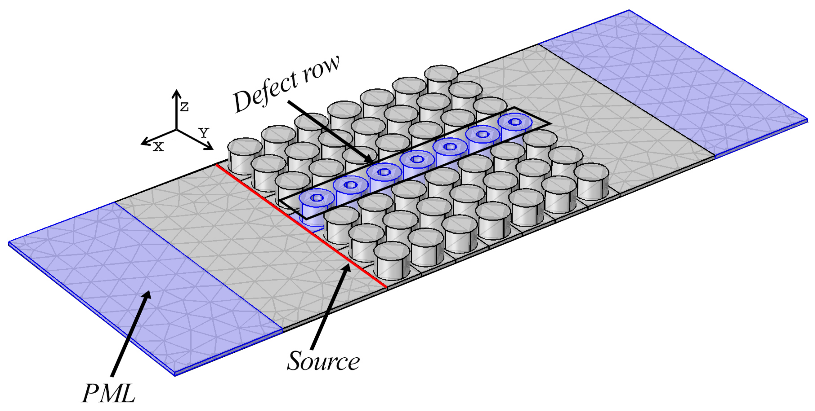
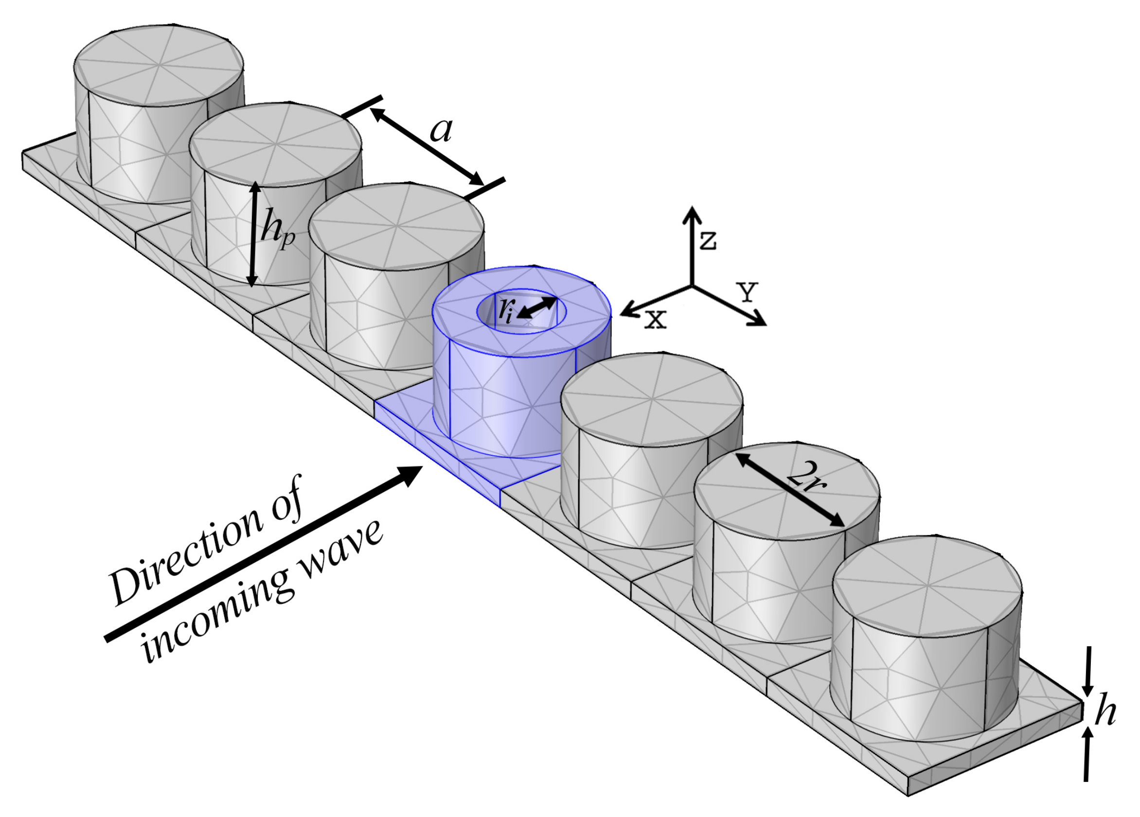
2. Model and Method of Simulations

The model we studied in the present paper is shown in Figure 1. The structure has a square lattice of hollow resonant pillars among of non-hollow perfect crystals standing on top of finite slab structure. Both the substrate and inclusion formed a monolithic unit made of silicon material with cubic symmetry of crystallographic oriented in axis x, y and z. The mass density, ρ is 2330 kgm−3, while the elastic constants C 11 , C 12 , and C 44 are respectively equal to 166 GPa, 64 GPa and 79.6 GPa. The relevant dimensions of hollow pillar radius, r i , high of pillar, h p , pillar diameter, d and slab thickness, h, were normalized to 4 mm unit of lattice constant, a.
Figure 2 represents the supercell model for dispersion calculation. The bulk structure consists of 7 unit cells containing a defect in between the neighbouring solid pillars. The dispersion of the proposed structure in X and Y directions was simulated numerically using solid mechanics modules in COMSOL Multiphysics software.
According to the Floquet theorem, the boundary condition of the unit cell can be formulated based on the following relationship:
u i ( x + a · m , y , z ) = u i ( x , y , z ) e ı ( a k x m ) e ı ( a k y m )
where k x is the wave vector in the x direction. Meanwhile, the propagation of elastic waves where the harmonic motions are assumed to be time-dependent is given by:
T i j x j = ρ ω 2 u i
where ρ represent the material density and the mechanical stresses T j k depends on the strain S l m :
T j k = C j k l m S l m
where C j k l m represents the elastic stiffness constants. The strain and displacement can be link with the following relationship:
S i j = 1 2 u i x j + u j x i
the propagation of wave with no external force can be desscribed as follows:
[ K u u ω 2 M u u ] × u = 0
where K u u and M u u are respectively the stiffness and mass matrices while u serves as the displacement vector at the mesh nodes. The formulation was used to solve the eigenvalue problem that produced the eigenfrequency in the first Brillouin zone.
The transmission spectra to understand the propagation of waves within the defect row of pillars can be solved using the FEM model in Figure 1 encompasses with perfectly matched layer (PML) as absorbing domain. The PML allowed the incoming mechanical wave to diminish gradually around the end boundary limit of the structure. With the PML acting as the absorbing medium, the structure was assumed infinite since the source of excitation do not interfer with the reflecting wave around the boundaries of the structure. To solve this, from the equation, then
1 γ j T i j x j = ρ ω 2 u i
where γ j is an artificial damping at position x j and is given by the following relation:
γ x ( x ) = 1 i σ x ( x x l ) 2
where x l is the coordinate at the beginning of PML and σ x is fixed according to the level of attenuation of PML space.

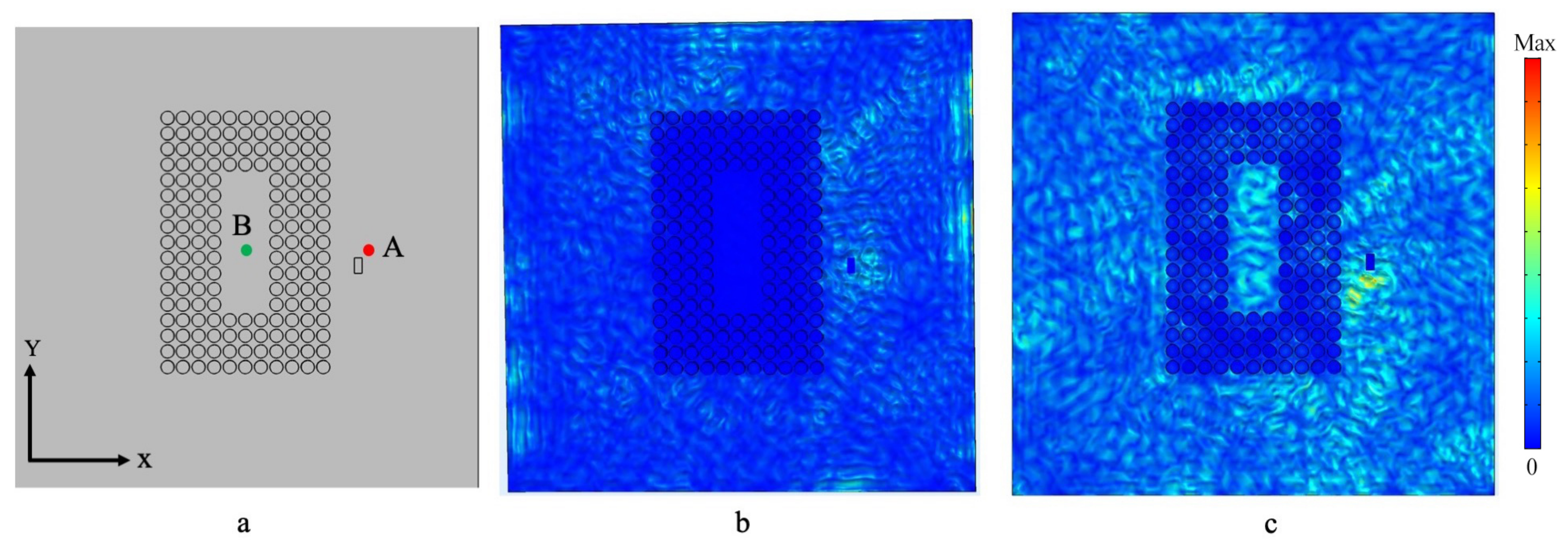
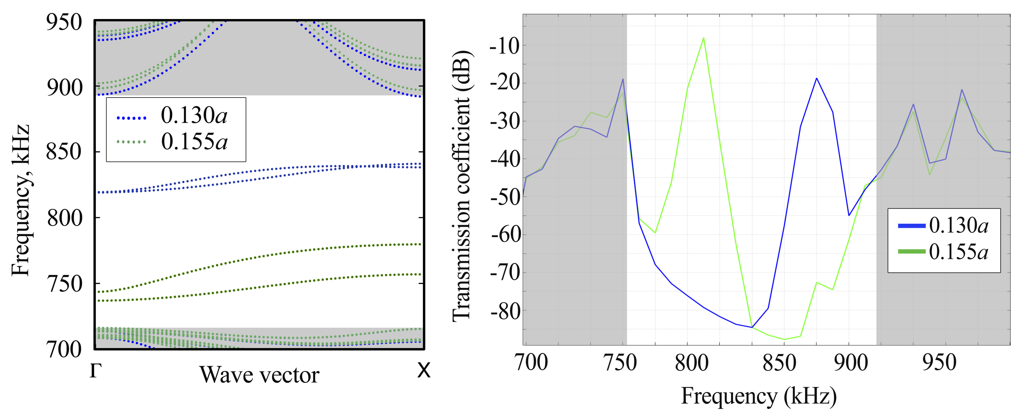
3. Result and Discussion

Before showing the result for hollow pillars as the mechanism of waveguiding, we simulated the reference band gap of the PnC with solid, non-hollow unit pillars, r i = 0. The dimension for pillar height, h p = 0.55a, pillar diameter, d = 0.84a and slab thickness, h = 0.1a produced three complete band gaps for perfect supercell structure. However the focus of this present study was on the largest of the three between 680 to 880 kHz where the respective dispersion curve and transmission spectra are shown in Figure 3. In the aforementioned frequency band gap domain, no incoming wave is allowed to pass through the perfect pillars that acts as the shielding region for the wave. The origin for the emergence of PnC band gap were described in the previous work [37,38,39].
To understand the nature of the result in Figure 3, a displacement study to illustrate the attenuation phenomena of the incoming wave was simulated. A square ring model to study the shielding effect of the band gap region with four rows of pillar units is presented in Figure 4a. Guided waves were excited based on the orthogonal displacement at point A (1 × 10⁻¹⁰ mm in the z-direction) with two incoming frequencies: 800 kHz within the BnG and 880 kHz at a frequency above the BnG region. As can be noted in Figure 4b, at band gap frequency 800 kHz, the waves were suppressed inside the area B and practically created a vacuum area from any surface stress. The dark blue and yellow colours in the diagram represent the minimum and maximum mechanical stress of the slab surface. With a shift frequency to 880 kHz above the band gap, the waves can pass the phononic region undisturbed and the vibration mode can be observed inside the ring-shaped. In summary, a delimitation of incoming wave trespassing was successfully achieved by the PnC structure owing to Bragg scattering at the wave within the BnG domain, confirming the numerically simulated BnG in Figure 3.
To create the trespassing frequency within the band gap region for filtering application, the inner-radius properties of the pillar were utilised to promote the frequencies divider by introducing a proportionate waveguides defects in the perfect PnC structure. Two hollows pillars with r i = 0.130a and 0.155a were considered with the aim to incite two separable range filtering frequencies. Figure 5 summarises the evolution of two frequencies shift corresponding to the previously mentioned r i 0.155a and 0.130a that do not exists in the native PnC. The dispersion curve and transmission spectra indicate filtering frequencies around 810 kHz and 880 kHz that uniquely represent the 0.155a and 0.130a waveguides. Although these branches are dispersive due to the interaction with the Lamb wave on the plate, they are the WGMs phenomena due to the hollow cylinders structure [24]. An immediate conclusion can be derived between the relationship of void opening with the frequency shifts within the band gap. By tuning the r i from 0.130a to 0.155a, a frequency move can be observed to a lower range. The limit size was limited equivalent to 0.130a and 0.155a to avoid any possible interaction between the waveguide frequency with the neighboring lamb wave frequency close to band gap lower and upper boundaries.
To demonstrate the propagation behaviour of the two waveguides in Figure 5, a simulated system was constructed consisting of both r i 0.130a and 0.155a on the same platform. In Figure 6a, two void radii were inserted with green and blue marking colours intended to distinguish r i = 0.155a (green) and 0.130a (blue) to initiate the transmission of waveguide frequencies. The displacement field magnitude of the guided waves are plotted in Figure 6b,c. The results demonstrate two importance observations. Firstly, the defect channels responded specifically to the frequency attributed to the transmission result. For instance, at frequency 810 kHz for r i = 0.155a, only the top channels (both linear and L-shaped) have a notable stress intensity that shows the wave are well-confined within the the defect route. Similarly, Figure 6c illustrates similar stress displacement when frequency shift hit 800 kHz for r i = 0.130a.
To produce a compact multi filtering frequencies system, a similar void defects as mentioned earlier were used to form a mono-channel defects consisting of the alternately hollow radius with r i = 0.155a and 0.130a surrounded with solid cylinders. The proposed system is illustrated in Figure 7a. Figure 7b shows a displacement profile for frequency f 0.130 = 880 kHz and f 0.155 = 800 kHz where the void cylinder shows alternate stress field between the two radius r i = 0.155a and 0.130a that correspond to their pass frequencies. The void cylinder can be used as a passive switch mechanism to reroute the filtering frequencies to another direction. Since the mono-channel consists of dual propagating frequencies within the same line, the frequencies can be singled-out to follow another path of filtering lines. However, the confined waves suffer from a diminution of energy as the wave approaches to the meeting end of the waveguide channel. Particularly for the case of 0.130a the linear channel shows significant loss of energy intensity on its straight channel. Figure 7c shows a transmission spectra of structured model in Figure 7a as compared to Figure 6a. A consistent transmission and elimination frequencies of propagation can be observed between the two structures suggesting that a bulky 16 × 7 (as in Figure 6a) filtering system can be reduced significantly into 7 × 7 unit cells model as illustrated in Figure 7a. The system eliminates the need to construct a multi-channel lines with their respective inter-solid cylinders to avoid interaction between void channel to filter several wavelengths. This can reduce the size of the whole system into a smaller-scale dimensions.

4. Conclusions

In conclusion, this study has numerically simulated a mono-channel filtering system consisting of dual pillars arranged alternately between two different hollow radii to selectively filter different frequencies. The band gap, the attenuation and transmitting waveguide frequencies with their respective stress field have been simulated based on the finite element methods. The proposed models showed a complete band gap at 680 kHz to 880 kHz and the two narrow passing frequencies f 0.130 , f 0.155 are respectively sensitive to hollow radius assigned to their filtering frequency. The displacement behaviour of the guiding line also shows that the propagating waves are well confined within the defect directions at their transmitting frequencies. The splitting of frequencies from a single-channel waveguides can also be achieved for the possible multiplexing application. The end system can minimise the size of normal-practised filtering technique that consists of several channels of waveguide lines to separate difference frequencies for an excellent candidate in sensing and communication applications. In addition, a full potential of the system can be further enhanced with filling elements inserted in the void volume such as liquid-based constituents. The result in the investigation can open a possibility for many acoustic-based applications like sensors, filters and resonators.

Author Contributions

M.S.F. designed the concept, performed most of the simulations and wrote the paper; N.A.A. helped with simulations and supervised the work. All authors have read and agreed to the published version of the manuscript.

Funding

Skim Geran Penyelidikan Fundamental (FRGS) code project FRGS/1/2019/TK04/UKM/02/1.

Institutional Review Board Statement

Not related.

Informed Consent Statement

Not related.

Data Availability Statement

Not related.

Acknowledgments

The authors acknowledge a financial support from Skim Geran Penyelidikan Fundamental (FRGS) code project FRGS/1/2019/TK04/UKM/02/1. The authors would also like to thank Mohd Farhanulhakim Mohd Razip Wee for his comments that greatly improved the manuscript.

Conflicts of Interest

The authors declare no conflict of interest.

References

  1. Hussein, M.I.; Leamy, M.J.; Ruzzene, M. Dynamics of phononic materials and structures: Historical origins, recent progress, and future outlook. Appl. Mech. Rev. 2014, 66, 040802. [Google Scholar] [CrossRef]
  2. Pennec, Y.; Djafari-Rouhani, B.; Vasseur, J.; Khelif, A.; Deymier, P.A. Tunable filtering and demultiplexing in phononic crystals with hollow cylinders. Phys. Rev. E 2004, 69, 046608. [Google Scholar] [CrossRef] [PubMed] [Green Version]
  3. Khelif, A.; Choujaa, A.; Benchabane, S.; Djafari-Rouhani, B.; Laude, V. Guiding and bending of acoustic waves in highly confined phononic crystal waveguides. Appl. Phys. Lett. 2004, 84, 4400–4402. [Google Scholar] [CrossRef]
  4. Laude, V.; Robert, L.; Daniau, W.; Khelif, A.; Ballandras, S. Surface acoustic wave trapping in a periodic array of mechanical resonators. Appl. Phys. Lett. 2006, 89, 083515. [Google Scholar] [CrossRef] [Green Version]
  5. Lin, S.C.S.; Huang, T.J. Acoustic mirage in two-dimensional gradient-index phononic crystals. J. Appl. Phys. 2009, 106, 053529. [Google Scholar] [CrossRef]
  6. El-Kady, I.; Olsson, R., III; Fleming, J. Phononic band-gap crystals for radio frequency communications. Appl. Phys. Lett. 2008, 92, 233504. [Google Scholar] [CrossRef]
  7. Wu, T.T.; Wang, W.S.; Sun, J.H.; Hsu, J.C.; Chen, Y.Y. Utilization of phononic-crystal reflective gratings in a layered surface acoustic wave device. Appl. Phys. Lett. 2009, 94, 101913. [Google Scholar] [CrossRef]
  8. Aly, A.H.; Mehaney, A. Low band gap frequencies and multiplexing properties in 1D and 2D mass spring structures. Chin. Phys. B 2016, 25, 114301. [Google Scholar] [CrossRef]
  9. Moradi, P.; Gharibi, H.; Fard, A.M.; Mehaney, A. Four-channel ultrasonic demultiplexer based on two-dimensional phononic crystal towards high efficient liquid sensor. Phys. Scr. 2021, 96, 125713. [Google Scholar] [CrossRef]
  10. Liu, Z.; Zhang, X.; Mao, Y.; Zhu, Y.; Yang, Z.; Chan, C.T.; Sheng, P. Locally resonant sonic materials. Science 2000, 289, 1734–1736. [Google Scholar] [CrossRef]
  11. Goffaux, C.; Sánchez-Dehesa, J. Two-dimensional phononic crystals studied using a variational method: Application to lattices of locally resonant materials. Phys. Rev. B 2003, 67, 144301. [Google Scholar] [CrossRef] [Green Version]
  12. Wang, G.; Yu, D.; Wen, J.; Liu, Y.; Wen, X. One-dimensional phononic crystals with locally resonant structures. Phys. Lett. A 2004, 327, 512–521. [Google Scholar] [CrossRef]
  13. Khelif, A.; Adibi, A. Phononic Crystals; Springer: Berlin/Heidelberg, Germany, 2015. [Google Scholar]
  14. Laude, V. Phononic Crystals; de Gruyter: Berlin, Germany, 2020. [Google Scholar]
  15. Deymier, P.A. Acoustic Metamaterials and Phononic Crystals; Springer Science & Business Media: Berlin/Heidelberg, Germany, 2013; Volume 173. [Google Scholar]
  16. Liu, J.; Guo, H.; Wang, T. A review of acoustic metamaterials and phononic crystals. Crystals 2020, 10, 305. [Google Scholar] [CrossRef]
  17. Pourabolghasem, R.; Khelif, A.; Mohammadi, S.; Eftekhar, A.A.; Adibi, A. Physics of band-gap formation and its evolution in the pillar-based phononic crystal structures. J. Appl. Phys. 2014, 116, 013514. [Google Scholar] [CrossRef] [Green Version]
  18. Miniaci, M.; Mazzotti, M.; Radzieński, M.; Kherraz, N.; Kudela, P.; Ostachowicz, W.; Morvan, B.; Bosia, F.; Pugno, N.M. Experimental observation of a large low-frequency band gap in a polymer waveguide. Front. Mater. 2018, 5, 8. [Google Scholar] [CrossRef] [Green Version]
  19. Sun, Y.; Yu, Y.; Zuo, Y.; Qiu, L.; Dong, M.; Ye, J.; Yang, J. Band gap and experimental study in phononic crystals with super-cell structure. Results Phys. 2019, 13, 102200. [Google Scholar] [CrossRef]
  20. Zhang, X.; He, J.; Takezawa, A.; Kang, Z. Robust topology optimization of phononic crystals with random field uncertainty. Int. J. Numer. Methods Eng. 2018, 115, 1154–1173. [Google Scholar] [CrossRef]
  21. Rayleigh, L. CXII. The problem of the whispering gallery. London Edinburgh Dublin Philos. Mag. J. Sci. 1910, 20, 1001–1004. [Google Scholar] [CrossRef] [Green Version]
  22. Raman, C.V.; Sutherland, G. On the whispering-gallery phenomenon. Proc. R. Soc. Lond. Ser. A Contain. Pap. A Math. Phys. Character 1922, 100, 424–428. [Google Scholar]
  23. Sturman, B.; Breunig, I. Acoustic whispering gallery modes within the theory of elasticity. J. Appl. Phys. 2015, 118, 013102. [Google Scholar] [CrossRef]
  24. Jin, Y.; Fernez, N.; Pennec, Y.; Bonello, B.; Moiseyenko, R.P.; Hémon, S.; Pan, Y.; Djafari-Rouhani, B. Tunable waveguide and cavity in a phononic crystal plate by controlling whispering-gallery modes in hollow pillars. Phys. Rev. B 2016, 93, 054109. [Google Scholar] [CrossRef] [Green Version]
  25. Li, F.; Xuan, M.; Wu, Y.; Bastien, F. Acoustic whispering gallery mode coupling with Lamb waves in liquid. Sensors Actuators A Phys. 2013, 189, 335–338. [Google Scholar] [CrossRef]
  26. Kaproulias, S.; Sigalas, M. Whispering gallery modes for elastic waves in disk resonators. AIP Adv. 2011, 1, 041902. [Google Scholar] [CrossRef]
  27. Jin, Y.; Pennec, Y.; Pan, Y.; Djafari-Rouhani, B. Phononic crystal plate with hollow pillars actively controlled by fluid filling. Crystals 2016, 6, 64. [Google Scholar] [CrossRef] [Green Version]
  28. Rostami-Dogolsara, B.; Moravvej-Farshi, M.K.; Nazari, F. Designing phononic crystal based tunable four-channel acoustic demultiplexer. J. Mol. Liq. 2019, 281, 100–107. [Google Scholar] [CrossRef]
  29. Wang, T.T.; Wang, Y.F.; Wang, Y.S.; Laude, V. Tunable fluid-filled phononic metastrip. Appl. Phys. Lett. 2017, 111, 041906. [Google Scholar] [CrossRef]
  30. Motaei, F.; Bahrami, A. Eight-channel acoustic demultiplexer based on solid-fluid phononic crystals with hollow cylinders. Photonics Nanostructures-Fundam. Appl. 2020, 39, 100765. [Google Scholar] [CrossRef]
  31. Konstantopoulou, A.; Aravantinos-Zafiris, N.; Sigalas, M. Tunable bandgaps and defect states in 3D phononic hollow structures. J. Appl. Phys. 2020, 127, 075101. [Google Scholar] [CrossRef]
  32. Motaei, F.; Bahrami, A.; Badri Ghavifekr, H. Magnetically controlled three-channel phononic switch. Mech. Adv. Mater. Struct. 2021, 1–9. [Google Scholar] [CrossRef]
  33. Watkins, A.A.; Bilal, O.R. Demultiplexing infrasound phonons with tunable magnetic lattices. Front. Mater. Rising Stars 2020 2021. [Google Scholar] [CrossRef]
  34. Wu, T.C.; Wu, T.T.; Hsu, J.C. Waveguiding and frequency selection of Lamb waves in a plate with a periodic stubbed surface. Phys. Rev. B 2009, 79, 104306. [Google Scholar] [CrossRef]
  35. Oudich, M.; Assouar, M.B.; Hou, Z. Propagation of acoustic waves and waveguiding in a two-dimensional locally resonant phononic crystal plate. Appl. Phys. Lett. 2010, 97, 193503. [Google Scholar] [CrossRef]
  36. Moradi, P.; Bahrami, A. Three channel GHz-ranged demultiplexer in solid-solid phononic crystals. Chin. J. Phys. 2019, 59, 291–297. [Google Scholar] [CrossRef]
  37. Zuo, S.; Huang, H.; Wu, X.; Zhang, M.; Ni, T. Low-frequency band gap of locally resonant phononic crystals with a dual-base plate. J. Acoust. Soc. Am. 2018, 143, 1326–1332. [Google Scholar] [CrossRef]
  38. Wu, T.T.; Huang, Z.G.; Tsai, T.C.; Wu, T.C. Evidence of complete band gap and resonances in a plate with periodic stubbed surface. Appl. Phys. Lett. 2008, 93, 111902. [Google Scholar] [CrossRef]
  39. Pennec, Y.; Djafari-Rouhani, B.; Larabi, H.; Vasseur, J.; Hladky-Hennion, A. Low-frequency gaps in a phononic crystal constituted of cylindrical dots deposited on a thin homogeneous plate. Phys. Rev. B 2008, 78, 104105. [Google Scholar] [CrossRef]
Figure 1. Phononic crystal with a square lattice of solid pillars on top of the plate structure. The void pillars are the filtering mechanism of the structure.
Crystals 12 00165 g001
Figure 2. Supercell to simulate dispersion band diagram.
Crystals 12 00165 g002
Figure 3. Dispersion and transmission coefficient for the band gap.
Crystals 12 00165 g003
Figure 4. (a) Square ring-shaped with 4 rows of solid cylinders to demonstrate the shielding phenomena of complete band gap frequency. The red dot is a point for wave generation. Displacement field simulated at (b) band gap frequency 800 kHz (c) 880 kHz at a frequency above band gap region.
Crystals 12 00165 g004
Figure 5. (left) Dispersion curve and (right) transmission spectra for r i = 0.130a to 0.155a.
Crystals 12 00165 g005
Figure 6. (a) The demultiplexer system consists of two waveguides channels, W 1 = 0.155a (green) and W 2 = 0.130a (blue) each with its own respective linear and L-shaped configuration (b) the computed transmission coefficient for W 1 = 0.155a at 810 kHz and (c) W 2 = 0.130a at 880 kHz. The red line on (b,c) indicate the excitation source of the model.
Crystals 12 00165 g006
Figure 7. (a) Model for dual filtering frequencies with single channel, (b) displacement field for (left) 0.130a at frequency 886 kHz and (right) 0.155a at frequency 800 kHz. The red arrow indicates the incoming wave (c) comparison between transmission spectra for multiple channel system in Figure 6a with mono-channel system in (a) for (left) r i = 0.130a and (right) r i = 0.155a. The pink region marks the transmission region for both waveguides r i = 0.130a and 0.155a.
Crystals 12 00165 g007
Publisher’s Note: MDPI stays neutral with regard to jurisdictional claims in published maps and institutional affiliations.

