
Preparation and Properties of Directionally Solidified Ni-Al Based Alloys Modified by Molybdenum

 , , , ,
Abstract
: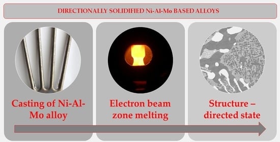
1. Introduction
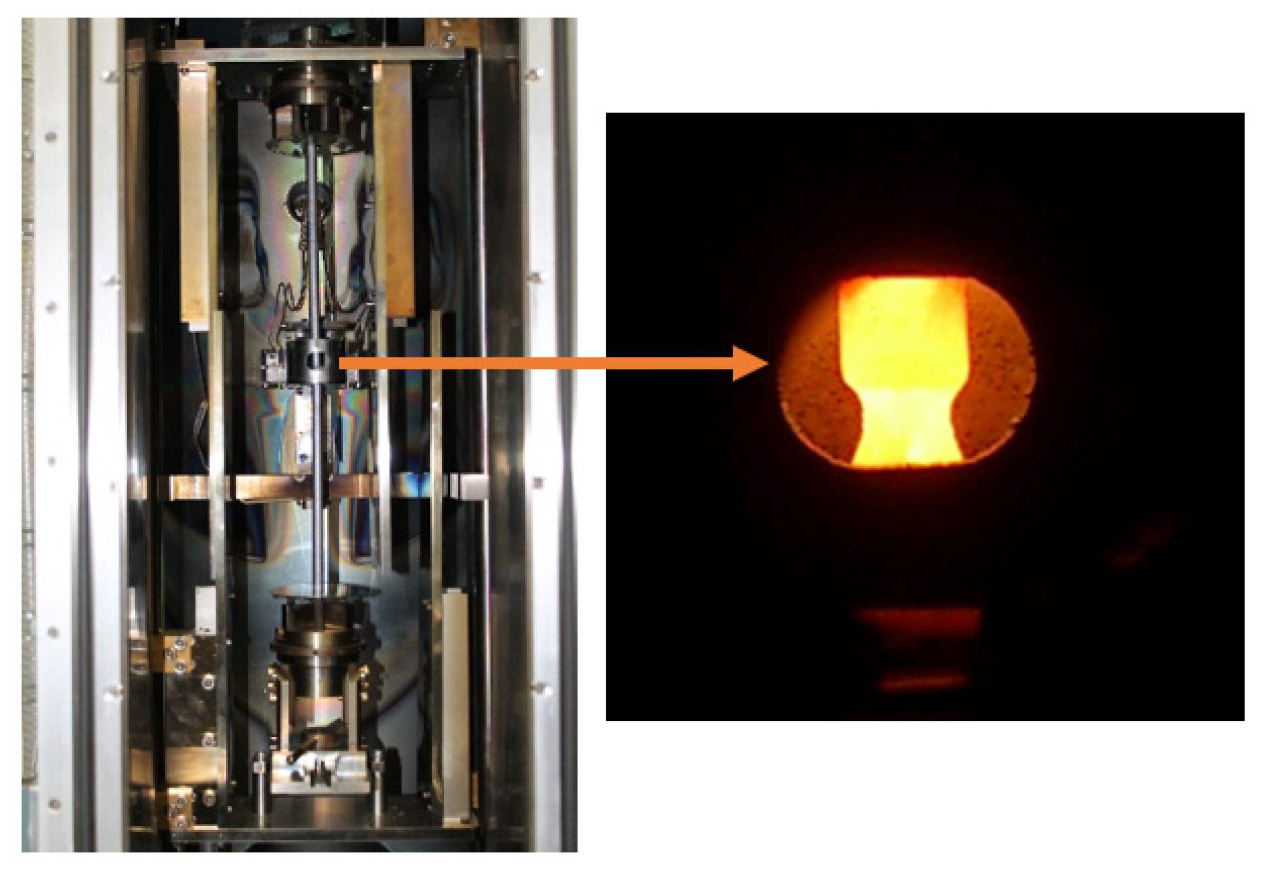
2. Materials and Methods
3. Results
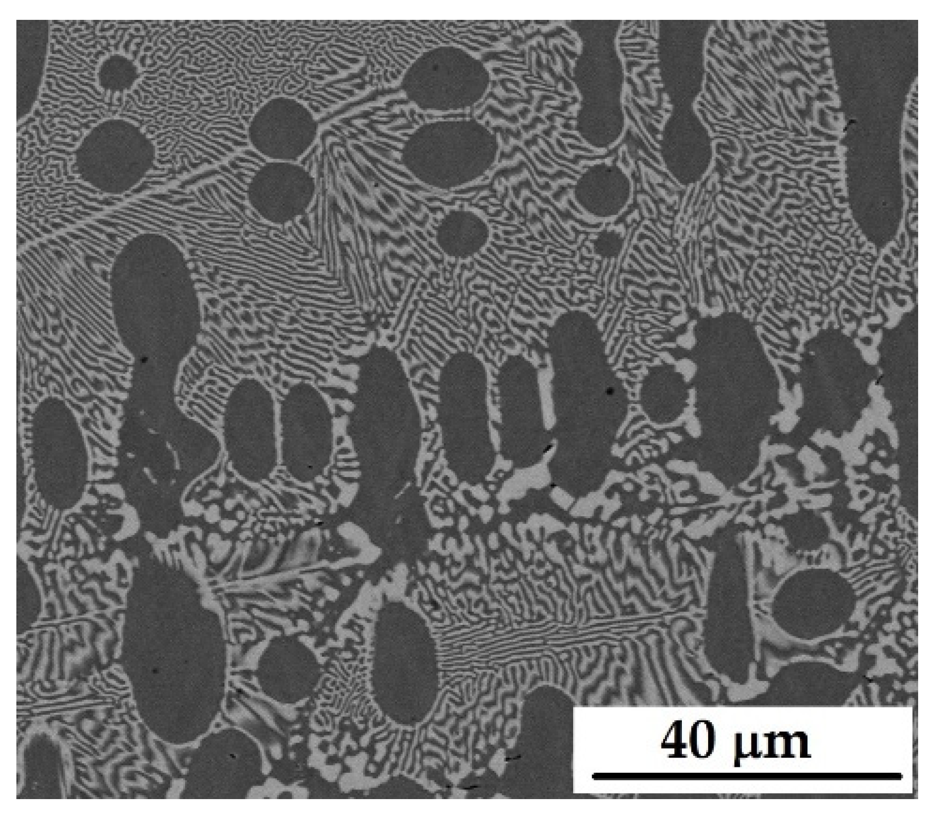
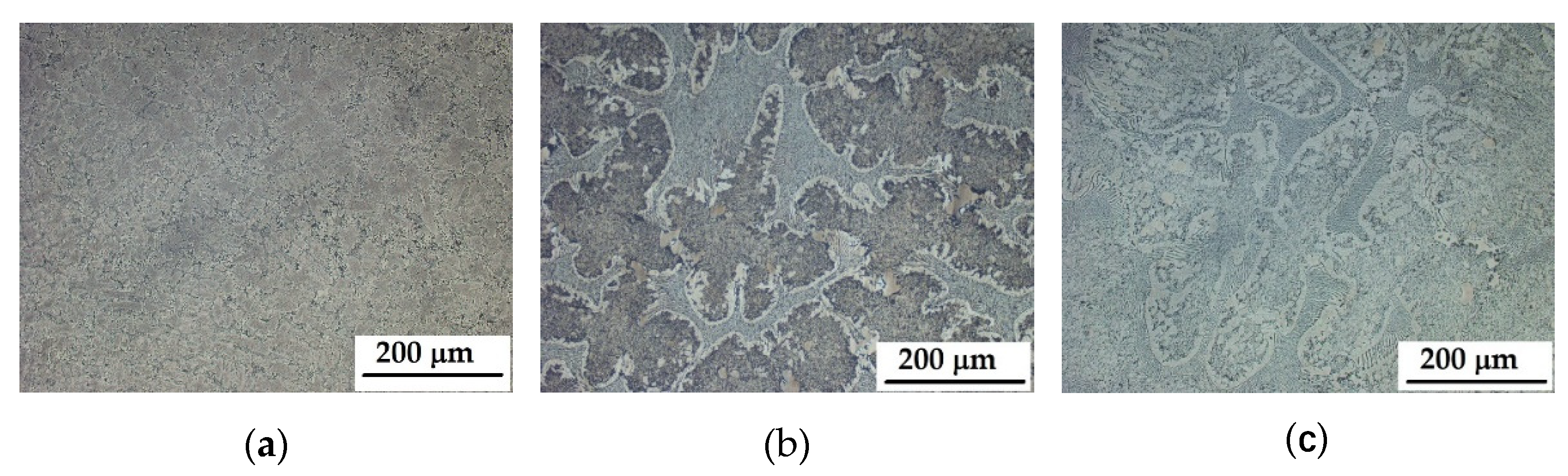
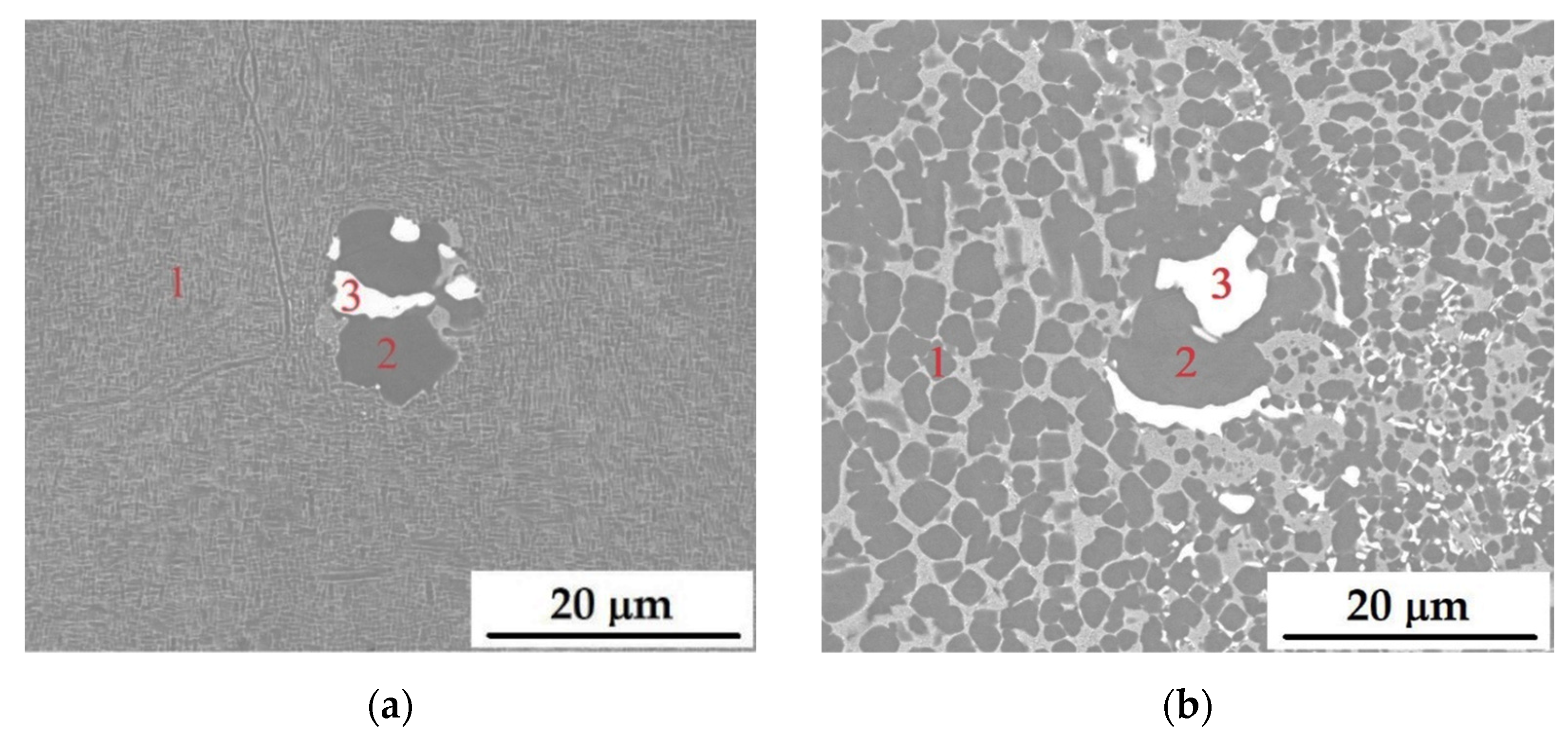
3.1. Microstructural Characterization of Alloys
3.2. Mechanical Properties of Alloys
4. Conclusions
Author Contributions
Funding
Institutional Review Board Statement
Informed Consent Statement
Data Availability Statement
Acknowledgments
Conflicts of Interest
References
- Stoloff, N.S.; Sikka, V.K. Physical Metallurgy and Processing of Intermetallic Compounds, 1st ed.; Springer Science & Business: Boston, MA, USA, 2012; 684p. [Google Scholar]
- Sikka, V.K.; Deevi, S.C.; Viswanathan, S.; Swindeman, R.W.; Santella, M.L. Advances in processing of Ni3Al-based intermetallics and applications. Intermetallics 2000, 8, 1329–1337. [Google Scholar] [CrossRef]
- Wessel, J.K. Handbook of Advanced Materials: Enabling New Designs, 1st ed.; John Wiley & Sons, Inc.: Hoboken, NJ, USA, 2004; 645p. [Google Scholar]
- Kong, Z.; Li, S. Effect of temperature and stress on the creep behavior of a Ni3Al base single crystal alloy. Prog. Nat. Sci. 2013, 2, 205–210. [Google Scholar] [CrossRef] [Green Version]
- Jiang, L.; Li, S.; Wu, M.; Han, Y. Grain competition mechanism of Ni3Al-based single crystal superalloys IC6SX. Mater. Sci. Forum 2013, 747–748, 205–210. [Google Scholar]
- Jiang, L.; Li, S.; Han, Y. Investigation on selection crystal behavior of a Ni3Al-based single crystal superalloy IC6SX. Procedia Eng. 2012, 27, 1135–1140. [Google Scholar] [CrossRef] [Green Version]
- Li, P.; Li, S.; Han, Y. Influence of solution heat treatment on microstructure and stress rupture properties of a Ni3Al base single crystal superalloy IC6SX. Intermetallics 2011, 19, 182–186. [Google Scholar] [CrossRef]
- Jiang, L.; Dou, X.; Wu, M.; Cai, M. Microstructure and heat treatment for Ni3Al-based single crystal alloy with different crystal orientation. Prog. Nat. Sci. Mater. Int. 2020, 30, 533–538. [Google Scholar] [CrossRef]
- Jiang, L.; Cui, Y.; Wuc, M.; Li, S.; Han, Y. Creep behaviour and dislocation mechanism of a Ni3Al based single crystal alloy IC6SX at 760 °C. Prog. Nat. Sci. Mater. Int. 2021, 31, 755–761. [Google Scholar] [CrossRef]
- Jiang, L.; Dou, X.; Wu, M. Effect of Stress on Creep Behavior of Single Crystal Alloy IC6SX at 980 °C. Int. J. Photoenergy 2020, 2020, 8844874. [Google Scholar] [CrossRef]
- ASM International. Ni-Mo Phase Diagram. In ASM Alloy Phase Diagrams Database [Online]; ASM International: Materials Park, OH, USA, 2009. [Google Scholar]
- Li, F.; Li, S.; Wu, Y.; Jiang, L.; Han, Y. Thermal cycle fatigue behaviors of a single crystal Ni3Al base alloy. Procedia Eng. 2012, 27, 1141–1149. [Google Scholar] [CrossRef] [Green Version]
- Ishak, M.; Takagi, H. The characteristics of unidirectional solidified Ni-Al-Mo alloys. Mater. Werkst. 2012, 43, 416–420. [Google Scholar] [CrossRef]
- Zhang, J.F.; Shen, J.; Shang, Z.; Wang, L.; Fu, H.Z. Elevated temperature tensile properties and deformation of directionally solidified NiAl–Mo in-situ composites. Mater. Charact. 2015, 99, 160–165. [Google Scholar] [CrossRef]
- Zhou, S.H.; Wang, Y.; Chen, L.-Q.; Liu, Z.-K.; Napolitano, R.E. Solution-based thermodynamic modeling of the Ni-Al-Mo system using first-principles calculations. Calphad 2014, 46, 124–133. [Google Scholar] [CrossRef]
- Malcharcziková, J.; Kursa, M.; Pohludka, M.; Kawulok, P.; Rusz, S.; Jordanovová, V. Deformation behaviour of Ni3Al based alloys in compression. In Proceedings of the 25th International Conference on Metallurgy and Materials METAL 2016, Brno, Czech Republic, 25–27 May 2016; Tanger: Ostrava, Czech Republic, 2016; pp. 1486–1491. [Google Scholar]
- Malcharcziková, J.; Kursa, M.; Pohludka, M.; Kawulok, P.; Gratza, P. High temperature mechanical properties of Ni3Al and Ni3Al-Mo alloys in compression. In Proceedings of the 26th International Conference on Metallurgy and Materials METAL 2017, Brno, Czech Republic, 24–26 May 2016; Tanger: Ostrava, Czech Republic, 2017; pp. 1874–1880. [Google Scholar]
- Ngo, T.D.; Kashani, A.; Imbalzano, G.; Nguyen, K.T.Q.; Hui, D. Additive manufacturing (3D printing): A review of materials, methods, applications and challenges. Compos. Part B 2018, 143, 172–196. [Google Scholar] [CrossRef]
- Qian, D.; Xue, J.; Zhang, A.; Li, Y.; Tamura, N.; Song, Z.; Chen, K. Statistic study of ductility-dip cracking induced plastic deformation in polycrystalline laser 3D printed Ni-based superalloy. Sci. Rep. 2017, 7, 2859. [Google Scholar] [CrossRef] [PubMed] [Green Version]
- Xia, M.; Gu, D.; Yu, G.; Dai, D.; Chen, H.; Shi, Q. Selective laser melting 3D printing of Ni-based superalloy: Understanding thermodynamic mechanisms. Sci. Bull. 2016, 13, 1013–1022. [Google Scholar] [CrossRef] [Green Version]
- Li, Y.; Chen, K.; Tamura, N. Mechanism of heat affected zone cracking in Ni-based superalloy DZ125L fabricated by laser 3D printing technique. Mater. Des. 2018, 150, 171–181. [Google Scholar] [CrossRef] [Green Version]


| Sample | Composition (wt.%) | Zone Pass Rate (mm/h) |
|---|---|---|
| A20 | Ni-8Al-14Mo | 20 |
| A50 | Ni-8Al-14Mo | 50 |
| B20 | Ni-8Al-20Mo | 20 |
| B50 | Ni-8Al-20Mo | 50 |
| Composition (at.%) | ||||
|---|---|---|---|---|
| Element | A50 | A20 | B50 | B20 |
| Analysis from point 1 | ||||
| Ni | 72.3 ± 0.5 | 71.5 ± 0.3 | 70.0 ± 0.4 | 71.1 ± 0.0 |
| Al | 17.9 ± 1.0 | 11.6 ± 0.3 | 20.1 ± 0.2 | 19.67 ± 0.0 |
| Mo | 9.8 ± 1.6 | 16.9 ± 0.0 | 9.9 ± 0.2 | 9.3 ± 0.1 |
| Analysis from point 2 | ||||
| Ni | 72.9 ± 0.0 | 72.3 ± 0.2 | 71.5 ± 0.1 | 72.1 ± 0.2 |
| Al | 22.6 ± 0.0 | 23.5 ± 0.4 | 24.6 ± 0.0 | 24.0 ± 0.3 |
| Mo | 4.5 ± 0.0 | 4.2 ± 0.3 | 3.9 ± 0.1 | 4.0 ± 0.0 |
| Analysis from point 3 | ||||
| Ni | 46.4 ± 1.3 | 6.1 ± 0.1 | 5.8 ± 0.2 | 5.0 ± 0.0 |
| Al | 2.7 ± 0.9 | 1.7 ± 0.2 | 3.0 ± 0.1 | 2.3 ± 0.2 |
| Mo | 50.9 ± 0.4 | 92.2 ± 0.3 | 91.2 ± 0.3 | 92.8 ± 0.0 |
| Sample | YS (MPa) | σmax (MPa) | εp (-) |
|---|---|---|---|
| A50 | 820 | 1199 | 0.50 |
| A20 | 680 | N/A | N/A |
| B50 | 815 | 1339 | 0.46 |
| B20 | 855 | 1330 | 0.38 |
Publisher’s Note: MDPI stays neutral with regard to jurisdictional claims in published maps and institutional affiliations. |
© 2022 by the authors. Licensee MDPI, Basel, Switzerland. This article is an open access article distributed under the terms and conditions of the Creative Commons Attribution (CC BY) license (https://creativecommons.org/licenses/by/4.0/).
Share and Cite
Malcharcziková, J.; Skotnicová, K.; Kawulok, P.; Kawulok, R.; Szurman, I.; Růžička, J. Preparation and Properties of Directionally Solidified Ni-Al Based Alloys Modified by Molybdenum. Crystals 2022, 12, 215. https://doi.org/10.3390/cryst12020215
Malcharcziková J, Skotnicová K, Kawulok P, Kawulok R, Szurman I, Růžička J. Preparation and Properties of Directionally Solidified Ni-Al Based Alloys Modified by Molybdenum. Crystals. 2022; 12(2):215. https://doi.org/10.3390/cryst12020215
Chicago/Turabian StyleMalcharcziková, Jitka, Kateřina Skotnicová, Petr Kawulok, Rostislav Kawulok, Ivo Szurman, and Jana Růžička. 2022. "Preparation and Properties of Directionally Solidified Ni-Al Based Alloys Modified by Molybdenum" Crystals 12, no. 2: 215. https://doi.org/10.3390/cryst12020215