Article

High-Precision Beam Angle Expander Based on Polymeric Liquid Crystal Polarization Lenses for LiDAR Applications

College of Optics and Photonics, University of Central Florida, Orlando, FL 32816, USA
*
Author to whom correspondence should be addressed.
Crystals 2022, 12(3), 349; https://doi.org/10.3390/cryst12030349
Submission received: 15 February 2022 / Revised: 27 February 2022 / Accepted: 28 February 2022 / Published: 4 March 2022
(This article belongs to the Special Issue Frontiers in Optics of Liquid Crystals and Displays)

Abstract

:
A novel beam steering angle expander is demonstrated by cascading two polymeric liquid crystal polarization lenses with different diopters. The lens module performs as a planar telescope, which has features such as a light weight, low cost, and high precision. The magnifier offers wide-angle, continuous steering when integrated with an active fine-angle beam steering device. The potential application for LiDAR is emphasized.

1. Introduction

Beam steering [1,2] has found widespread applications in near-eye displays, microscopy, and LiDAR (light detection and ranging). Both mechanical and non-mechanical beam controls have been developed [3,4,5,6,7]. Non-mechanical beam steering promises substantial benefits, and can be fulfilled by several approaches, including electrowetting [8,9], microlens arrays [10], polarization gratings [11,12], and optical phased arrays (OPA) [1,2]. Among them, OPA can offer quasi-continuous deflection angles with high efficiency, but the steering range is relatively narrow, depending on the electrode width. To extend the steering range, Xiao et al. [13] proposed to combine a Galilean telescope with an OPA, where the telescope comprises two refractive lenses—one positive and another negative. Recently, He et al. [14] demonstrated a miniatured telescope by replacing the refractive lenses with two polymeric liquid crystal (LC) microlens arrays, based on the Pancharatnam–Berry (PB) phase, also known as the geometric phase [15], at λ = 488 nm. Unlike a conventional refractive lens that utilizes the optical path difference to converge or diverge the beam, the PB lens produces the desired phase profile by spatially varying the LC directors in the azimuthal direction, which forms an ultra-thin flat LC lens. Moreover, such a PB lens offers prominent advantages, such as high efficiency, low cost, simple fabrication process, and good flexibility [16,17].
In this paper, we demonstrate a beam angle expander (BAE) composed of two polymeric LC lenses with diameters ~1.67 cm, working at λ = 1550 nm, a potential LiDAR wavelength. The incident angle is expanded two times, independent of the incident positions, by using two PB lenses with f/3.3 and f/1.6, respectively. A larger magnification factor can be achieved by optimizing the practical situation and the package volume. To the best of our knowledge, this is the first demonstration of high-quality polymeric LC PB lenses working at 1550 nm. Unlike PB devices designed for the visible wavelengths, working in the short-wavelength infrared (SWIR) region demands a 2.5x–3.5x thicker polymeric LC film to satisfy the required π phase change, providing that the same LC monomer is employed. Our experimental results prove that the LC alignment is still robust when the polymeric LC film is as thick as ~5.7 µm, even at the smallest local grating period (~5 µm) area. Such a new BAE can provide wide-angle continuous steering with the combination of a fine-angle beam steering device for LiDAR applications.

2. Working Principle

2.1. BAE Module

The BAE is composed of a smaller positive power (k1) PB lens and a larger negative power (k2) PB lens. The angle magnification is dictated by the two lens powers, which can be simply calculated by the ray-tracing method. Figure 1 shows the system configuration and the parameters involved in the ray tracing, where f1 and f2 denote the focal length of each lens, respectively. The magnification factor can be derived as follows:
θ m θ i n = h i n k 1 ,
h o u t = h i n + θ m d ,
θ o u t θ m = h o u t k 2 .
After some algebra, the output angle (θout) can be expressed as follows:
θ o u t = θ i n 1 d k 2 h i n k 1 k 2 d k 1 k 2 .
In order to make the output angle independent of the initial height (hin), the distance d should be adjusted to satisfy the following relationship:
k 1 k 2 d k 1 k 2 = 0 .
Then, the distance (d) between the two lenses is as follows:
d = f 1 + f 2 ,
In addition, the angle magnification is as follows:
θ o u t θ i n = f 1 f 2 .

2.2. PB Lens

The working principle of the PB phase effect in the Raman–Nath region can be illustrated by Jones matrix calculus [18], as follows:
J ± = 1 ± i ,
where J± indicates the Jones vectors of left- and right-handed circularly polarized light. The Jones matrix of a half-wave plate (HWP) with a spatially orientated angle φ(x) is expressed as follows:
M = R φ W π R φ ,
where R(φ) is the rotation matrix and W(π) is the Jones matrix of the half-wave retarder. Then, the Jones vector of output light can be derived as follows:
J ± = M J ± = i e ± i 2 φ J .
The output beam has opposite handedness to the input beam, and acquires a spatially variant 2φ phase.
The spatially variant phase pattern is reflected by the LC director orientation distribution. Equation (10) reveals that right-handed circular polarized (RCP) light and left-handed circular polarized (LCP) light experience an opposite phase profile when passing through the PB phase pattern. Therefore, the PB lens can be converging or diverging, depending on the incident circular polarization (LCP or RCP).

3. Experimental Results

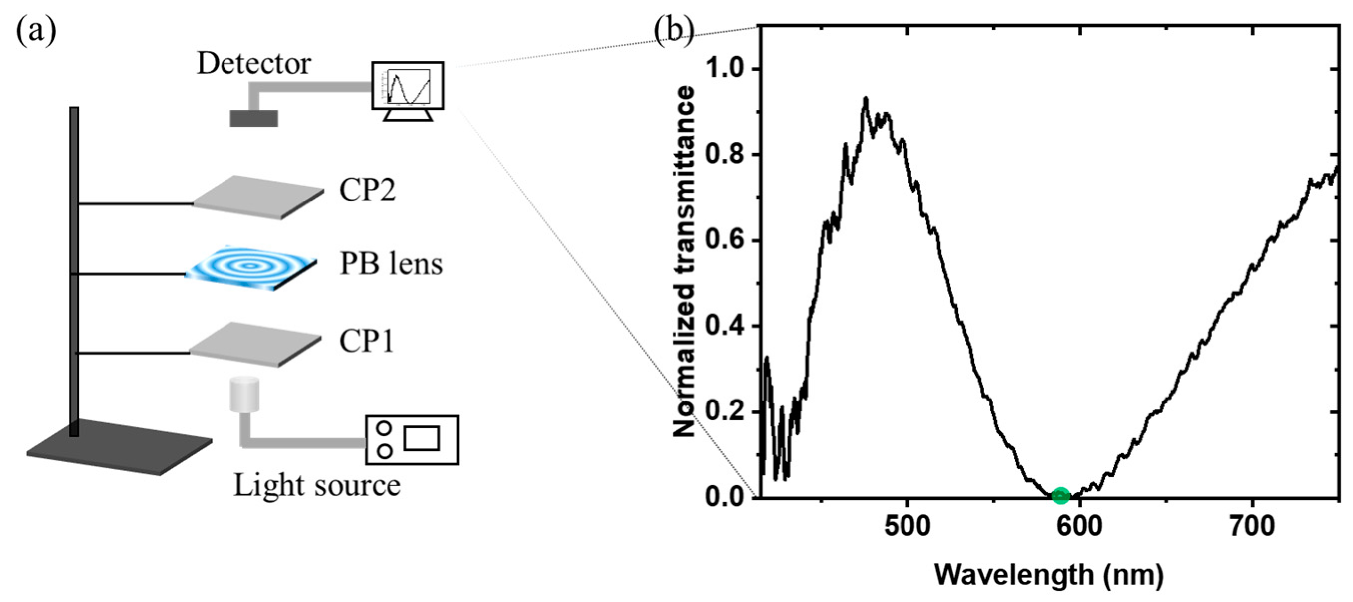
3.1. Infrared PB Lens Fabrication and Characterization

Polarization holography is a common method for producing such a spatially varying polarization field via the interference of two circularly polarized lights [19]. We developed a modified Mach–Zehnder interferometer for fabricating the PB lenses. A detailed description of the interferometer can be found in [20]. Of special attention is the selection of the optical power of the template lens (TL) employed in the interferometer, which determines the exposure pattern. For a diffractive lens, its optical power is highly dependent on the imaging wavelength, which obeys f1λ1 = f2λ2. In our experiment, the exposure wavelength (λ1 = 457 nm) is much shorter than the laser beam steering wavelength (λ2 = 1550 nm). As a result, the selection of TL power should be based on the designed optical power of the PB lenses at 1550 nm. The resulting interference pattern is recorded on the sample substrate coated with a photo-alignment layer. The photo-alignment material we used is Brilliant Yellow (BY), which was dissolved in a dimethylformamide (DMF) solution. Then, the substrate was exposed to interfering beams. BY is a kind of azo dye, whose azo molecules would rotate to align perpendicular to the polarization direction of the exposure light [21,22]. After exposure, we started the spin coating process. To achieve π phase retardation, the LC film thickness (dLC) should satisfy the following:
d LC = λ 2 Δ n ,
where λ is the incident wavelength and ∆n is the LC birefringence. The LC polymer is composed of the reactive mesogen RM257 (96.5%), the photo-initiator Irgacure 651 (3%), and the surfactant Zonyl 8857A (0.5%). The ∆n of RM257 is ~0.135 at 1550 nm. Thus, the film thickness should be ~5.7 µm. To acquire a high-quality LC alignment, we spin coated the LC film several times to achieve π phase retardation at the desired wavelength.
The LC polymer was diluted in toluene in a 1:4 ratio by weight. The spin-coating speed for each layer is summarized in Table 1. After each coating, a strong UV light (>40 mW/cm2), covering the whole LC layer, was used for adequate polymerization, which is essential for the next coating. An elegant way to determine how many layers should be coated is to observe which incident wavelength meets the half-wave condition after coating each layer. We built a simple testing setup (Figure 2a) to find the optimal working wavelength by measuring the system transmittance. The incident light passing through the first circular polarizer (CP1) becomes RCP light. At the optimal wavelength, the PB lens will maximumly convert RCP to LCP light; otherwise, the leaked RCP light will pass through the second circular polarizer (CP2). Consequently, the optimal wavelength should have the lowest transmittance. In other words, we stopped coating when the lowest transmittance was found at 1550 nm. Although the spectral range of our spectrometer is only from 400 nm to 1100 nm, we could use a reliable method to indirectly determine if the lens efficiency reaches its highest at 1550 nm. The film thickness that induces a π phase change at 1550 nm also brings about a 3π phase change at ~589 nm, based on the phase retardation equation. Figure 2b indirectly proves that the efficiency has achieved its highest at 1550 nm, after 8 LC layers have been deposited.
We fabricated two PB lenses with different diopters. We examined the lens quality in both macroscopic and microcosmic manners. Figure 3a shows the photograph of our fabricated PB lens. The black dashed circle indicates the effective area of the lens, where the diameter is ~1.67 cm. The observed images are from the ceiling fluorescent lamps in our labs. The lens surfaces are clear and uniform, except for some dust. To inspect the alignment pattern, we placed the PB lens under an optical microscope with crossed polarizers. The center view of the polarized optical microscope images for the PB lens is manifested in Figure 3b. The local grating period is the largest in the central area and gradually decreases along the radial direction. Figure 3c shows the fringes near the border of the lens, which are the most vulnerable part of the lens, due to them having the highest spatial frequency. The patterns demonstrate that the LC alignment is still robust, even when the film thickness reaches ~5.7 µm.

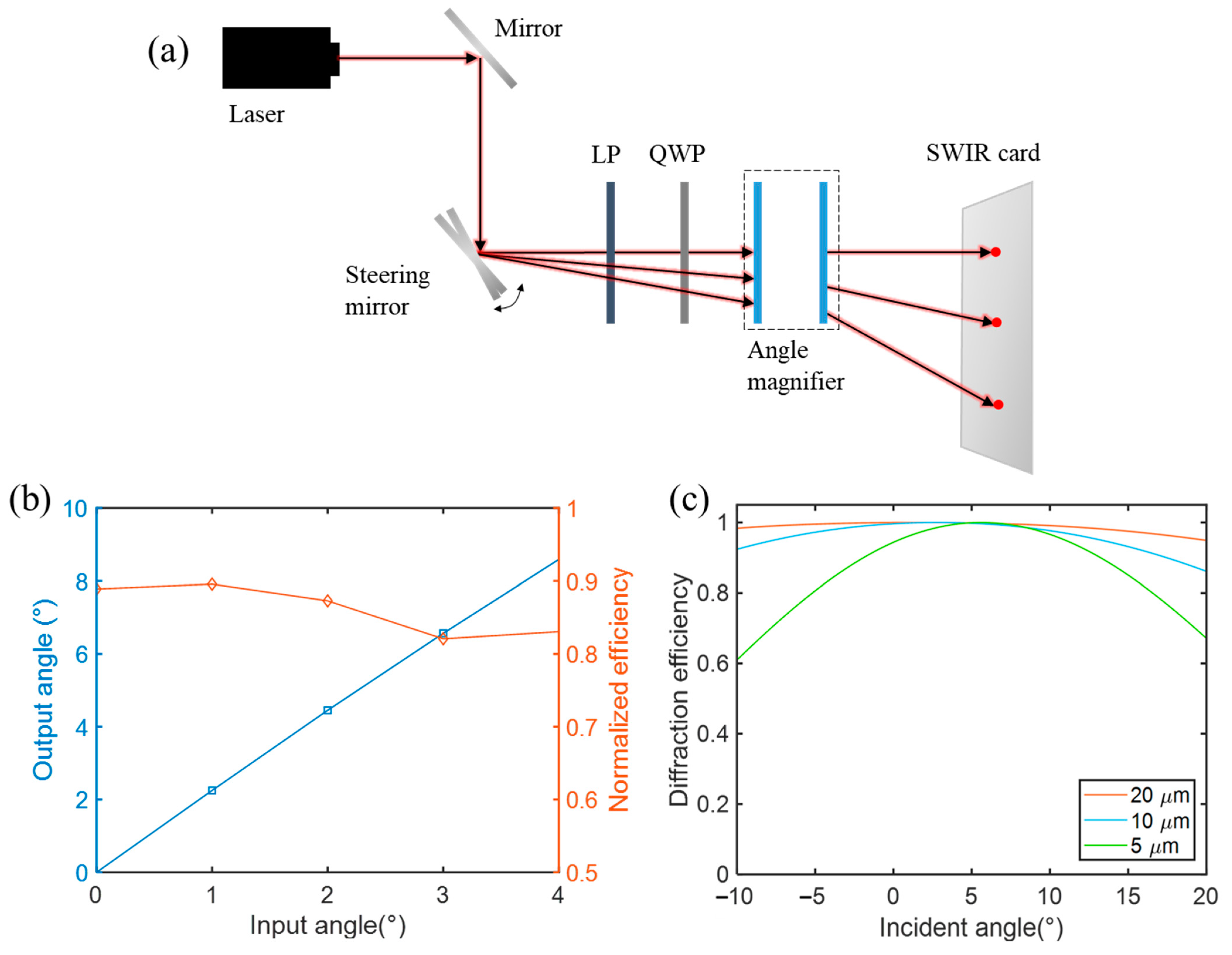
3.2. Angle Magnifier Performance

The measured focal lengths of the two PB lenses were ~5.6 cm and ~2.6 cm, respectively. To verify the feasibility of the BAE, we built a measurement setup. A mirror was mounted on a rotary stage to control the angle of incident light emitted from the laser diode (λ = 1550 nm). Additionally, a linear polarizer and a quarter-wave plate served to generate circularly polarized light. The separation between these two lenses was ~3 cm. A SWIR detector card was placed behind the lens module to record the output spot position, as Figure 4a depicts. Based on trigonometry, we can calculate the output angle and then the angle magnification. The measured results, as plotted in Figure 4b, match the predicted magnification (~2.1) well. To measure the system efficiency, we placed a power meter with a detector (Ge photodiode, 700–1800 nm) to read the power, and calculated the ratio of transmittance power between the system with the PB lens module and the system with two clean glass substrates, which serve as the reference. The measured efficiency is plotted in Figure 4b. The efficiency reaches ~90% near the normal incident angle, and then drops to ~83% as the incident angle increases. This is because the diffraction efficiency is dependent on the incident angle, especially when the incident beam hits the small grating period region of the lens.
We performed the numerical simulations based on rigorous coupled-wave analysis to demonstrate the relation between efficiency and incident angle at different periods [23]. Figure 4c has the following three implications: (1) the diffraction efficiency is dependent on the incident angle; (2) a larger grating period leads to a wider angular response; (3) the optimal incident angle can shift as the grating period becomes smaller. In the experiment, as the incident angle becomes larger, the intersection position on the lens is closer to the lens border, which has the smallest grating period. This means that the incident angle that hits the lens border is no longer 0°. Therefore, the efficiency at the small grating period could be improved by controlling the incident angle to make it closer to the optimal angle. A more direct and effective method is to apply a multi-twist LC structure to achieve a wide angular bandwidth to compensate for the off-angle efficiency loss [24]. Besides the inefficient angular response, the lens haze could also lead to efficiency loss. The origins of the haze are likely two-fold. The first is due to surface roughness, which can be improved by a better coating facility to enhance the film quality. The second is LC misalignment. A thicker LC film is more vulnerable to this defect, due to the multiple coating processes. In addition, the small grating period also poses a challenge to keeping the nematic LC directors well aligned on the top interface, due to the high volume of free energy. In this case, the LC directors on the top interface favor homeotropic orientation, resulting in alignment defects.

4. Discussion

In LiDAR applications, especially for autonomous driving cars, the two most frequently used detection wavelengths are 905 nm and 1550 nm. In the experiment, we only demonstrated how the BAE works at 1550 nm. However, the polymeric PB lens can be tailored to operate at nearly any wavelength, from visible to SWIR. To extend the operation wavelength to mid-wave IR, a thicker cell gap is required to satisfy the half-wavelength phase condition [11]. In the following, we will simulate the performance of BAE at 905 nm and 1550 nm.
The magnification, as indicated by Equation (6), can increase substantially if we enlarge the focal length difference between f1 and f2. However, Equation (7) reveals that there is a trade-off between the angle magnification and system volume. In other words, when it comes to a practical situation, the magnification should be dictated by the allowable system volume. The system volume of the BAE is determined by the diameter of the two employed lenses and the distance between them. It is, therefore, important to evaluate the trade-off between the magnification factor and system volume by taking some practical restrictions and assumptions into account.
If we conservatively assume that the smallest grating period of an on-axis LC-based transmissive PB lens can reach ~2 µm, then the corresponding f-number is f/0.64 at λ = 1550 nm and f/1.1 at λ = 905 nm. When the BAE is combined with an OPA, the distance between them is critical, and will influence the size of the whole system. In consideration of all these factors and constraints, we theoretically calculated the magnification factor by setting different gap distances (d1) between the OPA and BAE, as listed in Table 2. The BAE can be more compact by selecting a shorter focal length for L1 and L2, according to Equation (6). However, the whole design needs to follow the restrictions and assumptions discussed above. In Table 2, d1 and f1 are manually setting variables, and f2/# is set to 0.64 and 1.1 at different wavelengths. The other parameters can then be calculated according to Equations (1)–(7). The BAE is designed to accommodate a maximum incident angle of 5°. A larger incident angle requires redesign, since larger-sized lenses are needed. Assuming that the angular range of an OPA is ±5° at λ = 1550 nm, after integration with our BAE, the steering range can reach about ±45°. If the BAE is optimized at 905 nm, then the steering range is about ±25°.

5. Conclusions

We demonstrated a novel beam angle expander composed of two polymeric LC PB lenses, which can provide wide-angle continuous steering with the combination of a fine-angle beam steering device. Such a PB lens has potential applications in beam steering and SWIR imaging systems, as a novel optical combiner, because of its flat shape, light weight, low cost, and easy fabrication.

Author Contributions

Methodology, Y.L.; experiments, Y.L. and Z.L.; writing—original draft preparation, Y.L.; writing—review and editing, S.-T.W.; supervision, S.-T.W. All authors have read and agreed to the published version of the manuscript.

Funding

This research was partially funded by the Facebook (now Meta) distinguished faculty award.

Institutional Review Board Statement

Not applicable.

Informed Consent Statement

Not applicable.

Data Availability Statement

The data presented in this study are available from the authors upon reasonable request.

Acknowledgments

The authors are indebted to Qian Yang and Kun Yin for helpful discussions.

Conflicts of Interest

The authors declare no conflict of interest.

References

  1. Resler, D.P.; Hobbs, D.S.; Sharp, R.C.; Friedman, L.J.; Dorschner, T.A. High-efficiency liquid-crystal optical phased-array beam steering. Opt. Express 1996, 21, 689–691. [Google Scholar] [CrossRef]
  2. McManamon, P.F.; Bos, P.J.; Escuti, M.J.; Heikenfeld, J.; Serati, S.; Xie, H.; Watson, E.A. A review of phased array steering for narrow-band electrooptical systems. Proc. IEEE 2009, 97, 1078–1096. [Google Scholar] [CrossRef]
  3. Takashima, Y.; Hellman, B. Review paper: Imaging lidar by digital micromirror device. Opt. Rev. 2020, 27, 400–408. [Google Scholar] [CrossRef]
  4. Davis, S.R.; Farca, G.; Rommel, S.D.; Johnson, S.; Anderson, M.H. Liquid crystal waveguides: New devices enabled by >1000 waves of optical phase control. Proc. SPIE 2010, 7618, 76180E. [Google Scholar]
  5. He, Z.; Gou, F.; Chen, R.; Yin, K.; Zhan, T.; Wu, S.T. Liquid Crystal Beam Steering Devices: Principles, Recent Advances, and Future Developments. Crystals 2019, 9, 292. [Google Scholar] [CrossRef] [Green Version]
  6. Hoy, C.; Stockley, J.; Shane, J.; Kluttz, K.; Mcknight, D.; Serati, S. Non-Mechanical Beam Steering with Polarization Gratings: A Review. Crystals 2021, 11, 361. [Google Scholar] [CrossRef]
  7. He, Z.; Wu, S.T. Compact, Fast-Response, Continuous, and Wide-Angle Laser Beam Steerers. J. Soc. Inf. Display 2021, 29, 281–287. [Google Scholar] [CrossRef]
  8. Liu, C.; Li, L.; Wang, Q.H. Liquid prism for beam tracking and steering. Opt. Eng. 2012, 51, 114002. [Google Scholar] [CrossRef]
  9. Lee, J.; Lee, J.; Won, Y.H. Achromatic doublet electrowetting prism array for beam steering device in foveated display. Opt. Express 2022, 30, 2078–2088. [Google Scholar] [CrossRef]
  10. Akatay, A.; Ataman, C.; Urey, H. High-resolution beam steering using microlens arrays. Opt. Lett. 2006, 31, 2861–2863. [Google Scholar] [CrossRef]
  11. Kim, J.; Miskiewicz, M.N.; Serati, S.; Escuti, M.J. Nonmechanical Laser Beam Steering Based on Polymer Polarization Gratings: Design Optimization and Demonstration. J. Light. Technol. 2015, 33, 2068–2077. [Google Scholar] [CrossRef]
  12. Gou, F.; Peng, F.; Ru, Q.; Lee, Y.H.; Chen, H.; He, Z.; Zhan, T.; Vodopyanov, K.L.; Wu, S.T. Mid-wave infrared beam steering based on high-efficiency liquid crystal diffractive waveplates. Opt. Express 2017, 25, 22404–22410. [Google Scholar] [CrossRef] [PubMed]
  13. Xiao, F.; Kong, L. Angular magnification method of liquid crystal optical phased array based on telescope system. Int. Soc. Opt. Photonics 2013, 8906, 89062C. [Google Scholar]
  14. He, Z.; Yin, K.; Wu, S.T. Miniature planar telescopes for efficient, wide-angle, high-precision beam steering. Light Sci. Appl. 2021, 10, 134. [Google Scholar] [CrossRef] [PubMed]
  15. Pancharatnam, S. Generalized theory of interference and its applications. Proc. Indian Acad. Sci. Sect. A 1956, 44, 398–417. [Google Scholar] [CrossRef]
  16. Gao, K.; Cheng, H.H.; Bhowmik, A.K.; Bos, P.J. Thin-film Pancharatnam lens with low f-number and high quality. Opt. Express 2015, 23, 26086–26094. [Google Scholar] [CrossRef]
  17. Li, Y.; Zhan, T.; Wu, S.T. Flat cholesteric liquid crystal polymeric lens with low f-number. Opt. Express 2020, 28, 5875–5882. [Google Scholar] [CrossRef]
  18. Tabiryan, N.V.; Roberts, D.E.; Liao, Z.; Hwang, J.Y.; Moran, M.; Ouskova, O.; Pshenichnyi, A.; Sigley, J.; Tabirian, A.; Vergara, R.; et al. Advances in Transparent Planar Optics: Enabling Large Aperture, Ultrathin Lenses. Adv. Opt. Mater. 2021, 9, 2001692. [Google Scholar] [CrossRef]
  19. Kim, J.; Li, Y.; Miskiewicz, M.N.; Oh, C.; Kudenov, M.W.; Escuti, M.J. Fabrication of ideal geometric-phase holograms with arbitrary wavefronts. Optica 2015, 2, 958–964. [Google Scholar] [CrossRef]
  20. Li, Y.; Yang, Q.; Xiong, J.; Li, K.; Wu, S.T. Dual-depth augmented reality display with reflective polarization-dependent lenses. Opt. Express 2021, 29, 31478–31487. [Google Scholar] [CrossRef]
  21. Chigrinov, V.G.; Kozenkov, V.M.; Kwok, H.S. Photoalignment of Liquid Crystalline Materials: Physics and Applications; John Wiley & Sons: Hoboken, NJ, USA, 2008. [Google Scholar]
  22. Yin, K.; Xiong, J.; He, Z.; Wu, S.T. Patterning Liquid Crystal Alignment for Ultra-Thin Flat Optics. ACS Omega 2020, 5, 31485–31489. [Google Scholar] [CrossRef] [PubMed]
  23. Moharam, M.G.; Gaylord, T.K. Rigorous coupled-wave analysis of planar-grating diffraction. J. Opt. Soc. Am. A 1981, 71, 811818. [Google Scholar] [CrossRef]
  24. Zhang, S.; Chen, W.; Yu, Y.; Wang, Q.; Mu, Q.; Li, S.; Chen, J. Twisting structures in liquid crystal polarization gratings and lenses. Crystals 2021, 11, 243. [Google Scholar] [CrossRef]
Figure 1. Schematic illustration of the BAE consisting of two PB lenses. The magnified part is a detailed ray-tracing process for one beam, as an example.
Crystals 12 00349 g001
Figure 2. (a) Transmittance measurement setup. CP: circular polarizer. (b) Measured normalized transmission spectrum of the PB lens sandwiched between two CPs.
Crystals 12 00349 g002
Figure 3. (a) Photograph of the fabricated PB lens. The diameter is ~1.7 cm. Polarizing optical microscope images of the large optical power PB lens (b) at the central area, and (c) at the margin.
Crystals 12 00349 g003
Figure 4. (a) Schematic of the measurement setup. LP: linear polarizer; QWP: quarter-wave plate. The incident angle is tuned from 0° to 4°. (b) Performance of the beam angle expander. Dots represent the measured data and solid lines are visual guides. (c) Simulated angle-dependent efficiency of non-twist LC PB elements. Local grating period: 5 µm, 10 µm, and 20 µm.
Crystals 12 00349 g004
Table 1. Diluting ratio and coating speed for each layer.
Solute: SolventCoating Speed
1st LC layer1:41000 (30 s)
2nd–8th LC layer1:42000 (30 s)
Table 2. The parameters involved in the calculation for the whole magnification system. The incident angle is set at 5°. d1: the distance between OPA and BAE; f1: focal length of the first PB lens (L1); f2: focal length of the second PB lens (L2); d: the distance between L1 and L2; D1: diameter of L1; f1/#: f-number of L1; D2: diameter of L2; f2/#: f-number of L2; M: magnification factor. The minus sign of f2 indicates L2 is a negative lens.
d1 (cm)f1 (cm)f2 (cm)d (cm)D1 (cm)f1/#D2 (cm)f2/#M
1550 nm11−0.110.880.175.710.170.648.87
2−0.211.780.1711.430.330.649.37
21−0.120.870.352.850.190.647.87
2−0.221.770.3520.350.648.87
905 nm11−0.190.800.175.710.171.15.18
2−0.351.640.1711.430.311.15.68
21−0.240.760.352.850.211.14.18
2−0.381.610.3520.351.15.18
Publisher’s Note: MDPI stays neutral with regard to jurisdictional claims in published maps and institutional affiliations.

