Communication

Inverse Colloidal Crystal Polymer Coating with Monolayer Ordered Pore Structure

1
College of Materials Science and Engineering, Donghua University, Shanghai 201620, China
2
China National Inspection & Testing Centre for Ophthalmic Optic Glass and Enamel Products, Donghua University, Shanghai 201620, China
3
School of Energy and Materials, Shanghai Polytechnic University, Shanghai 201209, China
4
Modern Service Department, College of International Vocational Education, Shanghai Polytechnic University, Shanghai 201209, China
5
Institute of Functional Materials, Donghua University, Shanghai 201620, China
6
Shanghai Engineering Research Center of Advanced Thermal Functional Materials, Shanghai Polytechnic University, Shanghai 201209, China
*
Authors to whom correspondence should be addressed.
These authors contributed equally to this work.
Crystals 2022, 12(3), 378; https://doi.org/10.3390/cryst12030378
Submission received: 18 February 2022 / Revised: 6 March 2022 / Accepted: 8 March 2022 / Published: 11 March 2022
(This article belongs to the Section Hybrid and Composite Crystalline Materials)

Abstract

:
A functional lens coating, based on the structure of inversed colloidal photonic crystals, is proposed. The color-reflecting colloidal crystal was first prepared by self-assembly of nano-colloids and was infiltrated by adhesive polymer solution. As the polymer was crosslinked and the crystal array was removed, a robust mesh-like coating was achieved. Such a functional coating has good transmittance and has a shielding efficiency of ~9% for UV–blue light according to different particle sizes of the nano-colloids, making it an ideal functional material.

1. Introduction

Photonic crystals (PC), with a uniform structure, maintain long-range order at the nano–micro scale [1,2], and are endowed with photonic bandgap (PBG) properties due to the periodic arrangement of dielectric materials [3,4]. This property leads to many applications, such as photonic fibers, filter films, and lasers [5,6,7]. So far, PC materials have covered one-dimensional (1D), two-dimensional (2D), and three-dimensional (3D) structures, and many nano-photonic structures are inspired from natural PC materials with various 1D, 2D, and 3D structures formed through billions of years of evolution, such as opal gems, butterfly wings, and various cases [8,9]. At present, one of the most effective preparation methods of PC materials is to self-assemble nano-colloids into so-called colloidal (photonic) crystals (CPC) [6,10,11,12]. Such an assembly can efficiently diffract structural colors in the visible-light range, and the PBG can be adjusted according to Bragg’s law.
m λ 0 = 2 n a d 111 Sin θ ,
where m is the diffraction order, λ0 is the diffraction wavelength in air, d111 is the nearest lattice distance, na is the average refractive index, and θ is the observation angle between the incident light and the normal line of the CPC sample.
On the other hand, with the increase in the number of people wearing lenses, functional lenses are becoming more and more important, e.g., anti-ultraviolet, anti-fog, and anti-blue light [13]; these functions can be achieved by adding specific materials to the base material of the lens during the fore-surface coating of the lens using a relatively simple method [14]. In recent years, people have gradually realized that blue light may cause more serious harm to the human body than other wavelengths within the visible-light range. As is known to all, blue light (380–500 nm) is an important component of visible light, closest to ultraviolet (UV) and with the highest energy, which might penetrate the crystalline lens and reach the retina, thus causing damage to the retina. In addition, blue light may directly/indirectly cause cell damage in the macular area and affect fundus oculi health. Functional lens coatings for preventing blue light have become a hot topic in current research [15,16,17]. For instance, a poly(vinyl alcohol) (PVA) CPC film could achieve color filtering with a shielding effect of ~70% [18]. We also previously reported PC-based lens coatings for UV shielding [19].
Hence, we developed an anti-blue light lens coating based on a PC structure. A CPC was self-assembled on the front surface of the lens, and then PVA was chosen for filtration into the air void of CPC colloids [20]. Next, a uniform coating film was formed through crosslinking PVA during the drying process due to surface tension. At last, the CPC template was removed by solvent to obtain a coating film with better transparency. This functional polymer coating has good light transmittance and a long-range ordered PC structure with 20% UV/blue-light shielding efficiency, which can be an ideal lens coating film material.

2. Materials and Methods

2.1. Materials

Styrene, ammonium persulfate (APS), glutaraldehyde (GA, 25% aqueous solution), acrylic acid (AA), and PVA (99% hydrolyzed, DP = 1750 ± 50) were obtained from Shanghai Chemical Agent Co., Ltd. (Shanghai, China). Xylene of analytical grade was purchased from Sigma-Aldrich (St. Louis, MO, USA). Optical glasses (Essilor, n = 1.591, D = 75 mm, +00.00) were used as received. The glassware used in the experiments was cleaned with RCA solution (5:1:1 mixture of water, hydrogen peroxide (30%), and ammonia (28%)) at 75 °C for 30 min. Ultrapure water (18.2 MΩ·cm) was used in all experiments. All materials were used as received without further purification.

2.2. Preparation of Nano-Colloids

Monodisperse polystyrene (PS) nano-colloids were prepared following the universal boiling polymerization method [21]. First, 100 mL of water was added into a 250 mL three-mouth flask with 5 mL of AA as the buffer under gentle stirring. The system was heated in an oil bath to boiling, and then 40 mL of styrene was added as the monomer. Then, 0.2 g of APS was added as the initiator, the system was kept boiling for 30–60 min to obtain colloids with different diameters, and the reaction was terminated by an ice bath. The latex was centrifuged for 5 min (10,000 RPM) to remove the aggregates and then dialyzed ultrapure water to remove small molecules and impurities. After dialysis for over 14 days, the synthesized PS nano-colloids were cleaned and showed bright structural color.

2.3. Self-Assembly of CPC onto Lens Surface

To form an opaline template with PS nano-colloids on the surface of the lens, the vertical deposition method was utilized (Figure 1A). A diluted PS dispersion (0.1 wt.%) was poured into a beaker; then, 0.1 wt.% SDS was added as a surfactant, and the lens was immersed in the dispersion. The beaker was placed in an oven at 60 °C for 72 h. As the solvent volatilized, the PS nano-colloids were self-assembled on the surface of the lens due to the capillary force, according to the mechanism shown in Figure 1B. The CPC template showed different diffraction colors according to Bragg’s law (see Figure 1C).

2.4. Polymer Infiltration and Template Removal

Preparation of an inverse opal coating (IOC) was achieved by polymer solution permeation and template etching. The PVA powder was firstly dissolved in water at 100 °C for 2 h to prepare a 3 wt.% transparent PVA solution. Then, 1% diluted GA solution was added as the PVA solution was cooled to 30 °C, and the mixture was quickly poured onto a lens tilted at 30°. The PVA mixture was allowed to infiltrate the CPC, and the lens was immediately placed in an oven at 60 °C for 15 min after infiltration. As the PVA crosslinking film was formed, the coated side of the lens was immersed in 50% xylene/water solvent for 3 s and then washed with ultrapure water to etch the PS CPC template. The immersing–washing treatment was repeated five times to completely remove CPC, and the IOC lens was obtained.

2.5. Characterizations

The particle size and CPC structure of PS nano-colloids were characterized by an S-4800 (Hitachi, Tokyo, Japan) scanning electron microscope (SEM). The PBG of all CPC materials was measured by a USB 4000-XR1-ES (Ocean Optics, Orlando, FL, USA) fiber-optic spectrometer with a DH-2000-BAL (Ocean Optics) light source; the optical data were collected within a wavelength range of 200–1000 nm. Optical photographs were captured using an EOS 6D (Canon) digital camera with a 272E (Tamron) macro lens.

3. Results and Discussion

3.1. Experimental Design and Feasibility

We initially designed two other facile routes, one of which was to mix the PS crystalline suspension with PVA solution, and then prepare the PC thin film via a “one-pot” method, where the CPC is immobilized as the PVA solution dries and forms a film [18]. However, due to the high viscosity of PVA solution and the nonplanar structure of the lens surface, It is difficult to accurately control the solute content of PVA and accurately control the CPC array, resulting in an irregular crystalline array surrounding the PVA polymer, as shown in Figure 2A.
Another route was to use our previously reported spray-coating method, a rapid preparation method of CPC, onto the lens surface [19]. However, we found that the formation of ordered CPC during spraying requires at least 10 layers of stacking, and the nonuniform bottom layer might affect the penetrating and coating of the PVA; as shown in Figure 2B, the lower layers of the spray-coated CPC were not closely packed in contrast to the upper layers.
On the basis of the results, we finally chose the current method to prepare CPC template materials with an ordered structure and uniform layers, and we ensured the optical properties and content consistency of the obtained products. The competition mechanism during vertical deposition of CPC is shown in Figure 1B, where Ve is the evaporation rate of the solvent, Vc is the crystallization rate of PS nano-colloids, Jw is the water influx, Jp is the particle influx, and h is the height (thickness) of the crystal array. As the substrate was vertically immersed in the nano-colloid suspension, the liquid level gradually decreased with the evaporation of the solvent, and the nano-colloids were closely arranged on the substrate due to the capillary force, thus forming an ordered stack array. Such a method can be optimized to adjust the growth rate of crystallization by changing the parameters such as dip angle of the substrate, evaporation rate of the solvent (temperature, solvent), and capillary force (surfactant), which can effectively control the assembly properties. As a matter of fact, in this experiment, since the PS nano-colloids and the lens were both hydrophobic polymer materials, surfactant was added to increase the adhesion force between the nano-colloids and the lens.

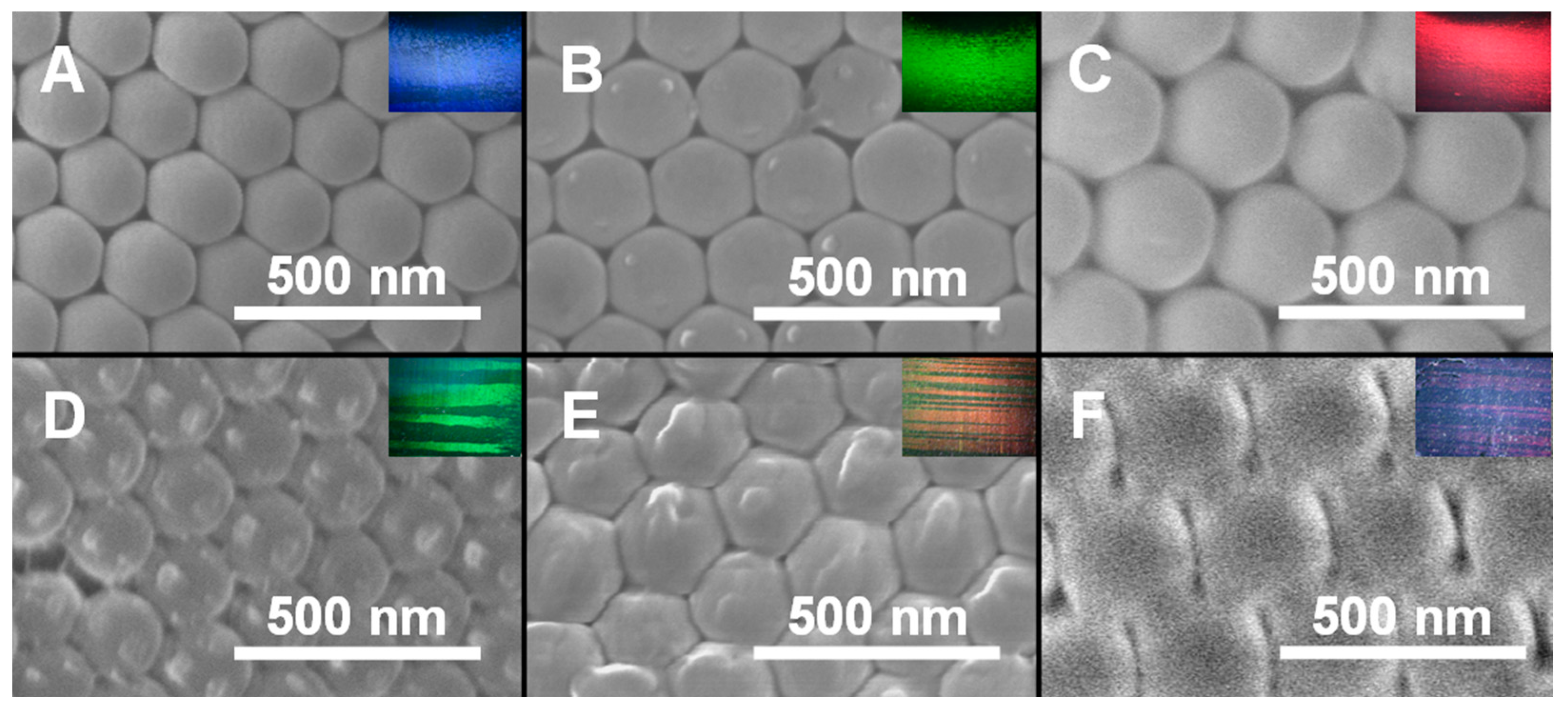
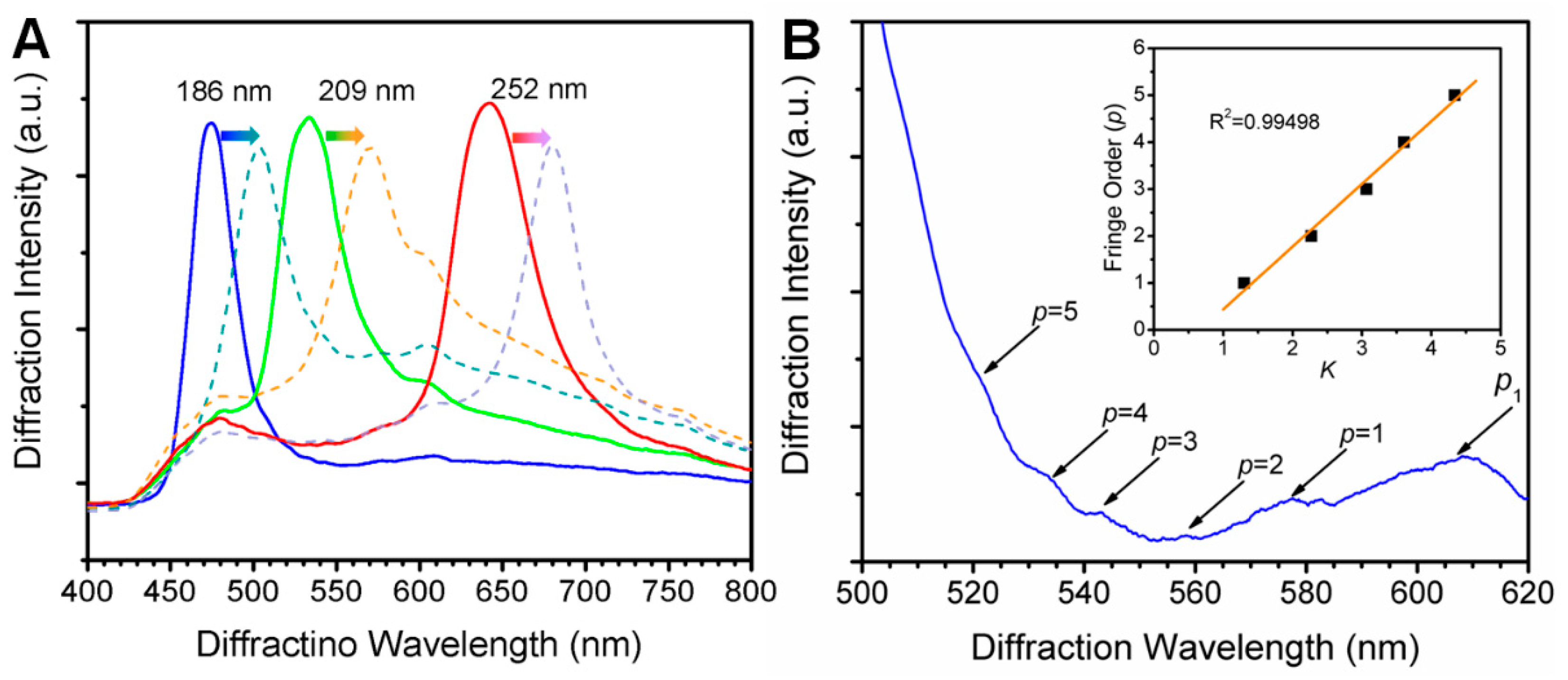
3.2. Diffraction Properties of CPCs

According to Bragg’s law, the diffraction wavelength (i.e., PBG) of CPC can be simply tuned by changing the particle size of nano-colloids to adjust the lattice distance, thus showing different diffraction colors with the shifting of the diffraction wavelength. CPCs constructed by PS nano-colloids with different particle sizes (186, 209, and 252 nm) were prepared onto the fore surfaces of the lenses to prove the feasibility of the coating method.
As can be seen from Figure 3A–C, all the samples prepared with different particle sizes had ordered hexagonal arrangement, consisting of the typical face-centered cubic (FCC) CPC structure. The inserts also show the bright structural color of samples. Accordingly, in Figure 3D–F, it is obvious that, after infiltration of PVA, the PS CPC template maintained the original hexagonal arrangement, and the PS nano-colloids were surrounded with PVA polymer. By observing the corresponding structural colors in the inserts, it was found that there were significant changes compared with those before PVA infiltration.
Specifically, as plotted in Figure 4A, the diffraction peaks of CPCs assembled with 186, 209, and 252 nm PS nano-colloids were located at 473.97, 533.56, and 642.85 nm, respectively. After PVA infiltration, the diffraction peaks were red-shifted to 503.76, 570.39, and 680.59 nm, respectively.
Since the (111) plane of the FCC CPC was observed in the experiment, and only the first-order diffraction was considered, then Equation (1) could be rewritten as
λ 0 = 2 n a 2 / 3 D ,
where D is the particle size of the nano-colloids.
Thus, the theoretical PBG of the CPCs constructed by different PS nano-colloids can be calculated and recorded together with the measured values in Table 1.

3.3. Effective Refractive Index Correction

After the CPC templates were infiltrated with PVA, the air interval between the PS nano-colloids was replaced by PVA; hence, the average refractive index changed. Since the refractive index of PVA was larger than that of air, the diffraction wavelength red-shifted after PVA infiltration. Such a red shift can be predicted according to the refractive index equation.
n a 2 = i n i 2 φ i
where φ is the volume fraction. For CPC templates, PS nano-colloids were assembled into an FCC arrangement, whose volume fraction should be 74%, while the remaining 26% was air, i.e., φPS = 0.74 and φair = 0.26. Then, nPS = 1.59 and nair = 1.0 were substituted into Equation (3), yielding na1 = 1.4597. Similarly, for CPCs after PVA infiltration, since PVA replaced air, φPS = 0.74 and φPVA = 0.26. Then, nPS = 1.59 and nPVA = 1.49 were substituted into Equation (3), yielding na2 = 1.5746. Then, λ could be predicted by
λ1/λ2 = na2/na1.
Thus, the diffraction wavelengths of CPC-PVA samples corresponding to 186, 209, and 252 nm PS CPC were 508.03, 571.90, and 689.05, respectively, which are consistent with the calculated values as can be found in Table 1.
In addition, in Figure 4B, a series of weak peaks, known as Fabry–Pérot fringes (FPF), can be also observed on the side of the main peak of the diffraction spectrum, caused by the isotropic interference of the CPC films [22]. FPF can be considered as a nondestructive parameter for thickness prediction of crystal films. FPF usually occurs as the crystal possesses a uniform structure with a thickness less than 8 μm [23]. As the maximum interference peak λl = 607.3 nm was observed in the diffraction spectrum and the actual average refractive index na = 1.56, the correlation coefficient K value of the sample could be calculated, and the specific values are shown in Table 2 (the calculation of the thickness (T) is listed in Supplementary Materials). Moreover, the relationship between interference order and correlation coefficient K is plotted in the inset of Figure 4B, showing good linearity (R2 = 0.99498).

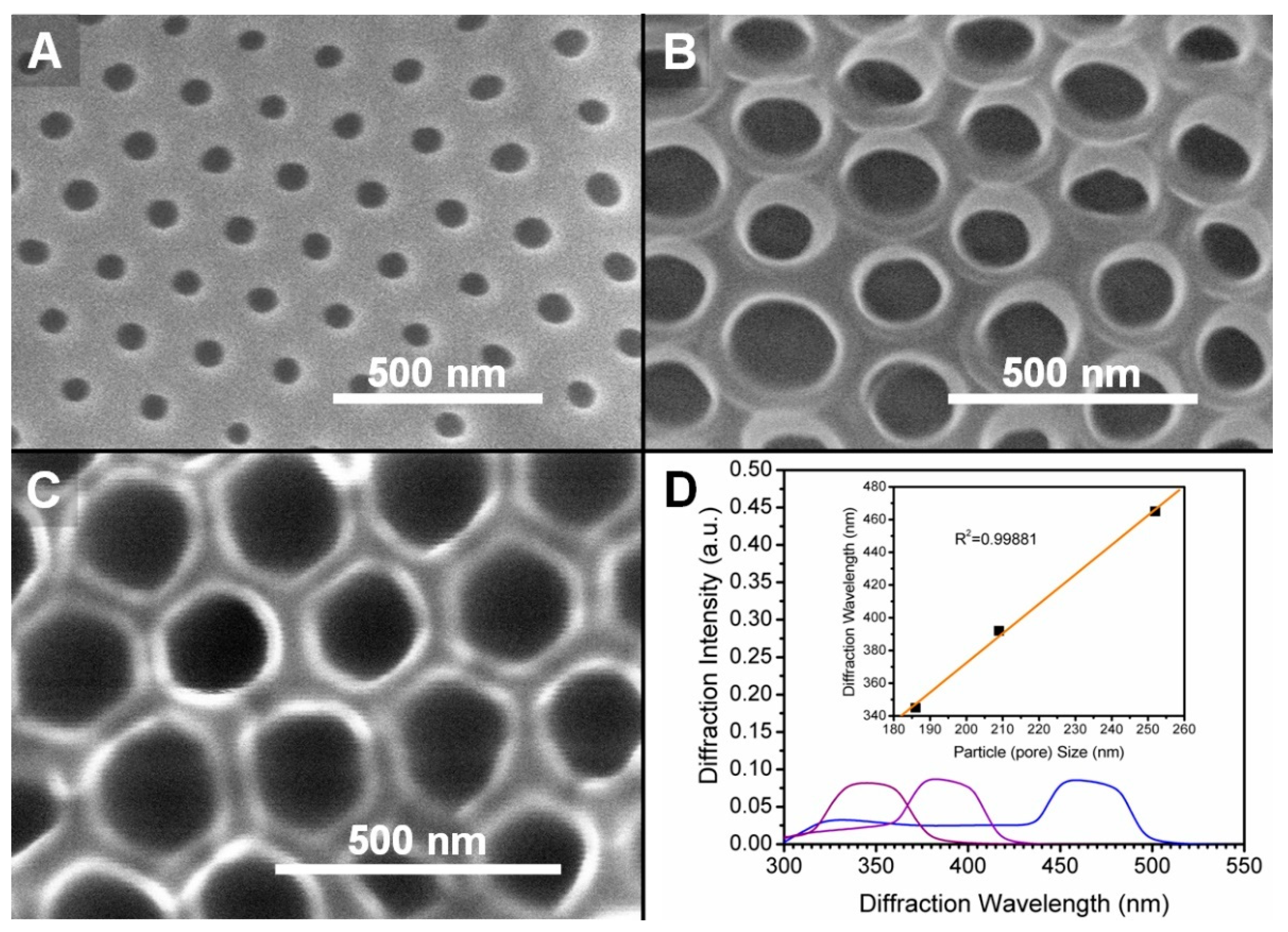
3.4. Characterization of IOC

To obtain a coating with higher transparency, as well as to achieve the purpose of anti-blue light, we further dissolved PS with a selective solvent while the PVA film was retained. Generally, a reverse structure could be obtained after scarifying the CPC template, which was a honeycomb-like PC called inverse opal. An interesting phenomenon can be found in Figure 5A–C, whereby single-layer mesh structures of PVA-IOCs were observed following the formation of macropores after CPC templates were etched, and no continuous network structure could be observed in the lower layer; thus, it could be considered a 2D PC structure. The backward diffraction intensity of a 2D PC array is usually weak (<10%), and a mirror is often used behind the 2D PC to reflect the forward-diffracted light to enhance the diffraction. Combined with the reflection of forward-diffracted light and the reflection of undiffracted incident light (zero-order diffraction), the diffraction efficiency of the net incident light could reach 70–80% [24]. Thus the advantage of this PVA-IOC structure lies in its higher light transmittance and lower diffraction intensity.
Figure 5D shows the diffraction spectrum of PVA IOCs with different pore sizes. It can be found that the PBG of IOC prepared with 186, 209, and 252 nm PS CPC as sacrifice templates was located at ~345, 392, and 465 nm, respectively, and the linear relationship was as follows [25]:
λIOC = 1.80279D + 11.86457 (R2 = 0.99881),
where D is the particle size of the nano-colloids.
Here, we noticed that, although the PGB of the IOC sample also showed good linearity, the ratio of the slope to the opal structure sample decreased. This may be due to the different structural stability during the formation of the reversed structure [26,27]. The CPC-PVA with a larger pore size (i.e., 252 nm) shrank more during the etching process, whose diffraction wavelength exhibited a larger blue-shifted than that of the CPC-PVA with smaller pore sizes, resulting in a decrease in the linear slope of the diffraction diameter plots.
For the diffraction wavelengths of this series of IOCs, 345, 392, and 465 nm could correspond well to UV, violet–indigo, and blue regimes, respectively, and the diffraction intensity of CPC was significantly lower than that of 3D opal, by approximately 8–9%. Such an IOC has the potential to be used as a protective film for UV/blue light. We anticipate that this research can find future applications or inspire further research for functional CPC materials.

4. Conclusions

In this research, a colloidal photonic crystal layer was deposited on the surface of a lens, and PVA was then crosslinked as a coating. Then, an inverted crystal was formed by etching the crystal template to reduce the forward reflection while enhancing the transmittance. The preparation process was mild without damaging the lens since the materials utilized were noncorrosive. Such an IOC prepared with PS nano-colloids with different sizes could achieve an 8–9% UV/blue-light shielding effect; hence, it has certain potential applications as functional coatings.

Supplementary Materials

The following supporting information can be downloaded at https://www.mdpi.com/article/10.3390/cryst12030378/s1: Figure S1. The relationship between diffraction wavelength (i.e., PBG) of CPC samples and particle size of PS nano-colloids; Figure S2. Thickness (T) and layer (L) analysis of as-prepared 186 nm PS CPC; calculation process of T and L by FBF method. Figure S3. Fourier transform infrared spectroscopy (FTIR) spectra of PVA and PVA/GA.

Author Contributions

The project was designed by W.T. and C.C.; L.W. and Z.C. prepared the samples; Z.H. and Z.C. conducted the SEM test; Z.C. collected optical data; L.W. wrote the paper under the supervision of W.J., J.Y. and C.C.; X.N., W.T. and C.C. revised the paper. All authors have read and agreed to the published version of the manuscript.

Funding

This research was funded by the State Key Laboratory for Modification of Chemical Fibers and Polymer Materials and China National Inspection and Testing Center for Ophthalmic Optic Glass and Enamel Products, the Fundamental Research Funds for the Central Universities (2232021G-07, 2232022G-07), the key subject of the Shanghai Polytechnic University (Material Science and Engineering, XXKZD1601), and the Gaoyuan Discipline of Shanghai Materials Science and Engineering.

Institutional Review Board Statement

Not applicable.

Informed Consent Statement

Not applicable.

Data Availability Statement

Not applicable.

Conflicts of Interest

The authors declare no conflict of interest.

References

  1. Yablonovitch, E. Inhibited spontaneous emission in solid–state physics and electronics. Phys. Rev. Lett. 1987, 58, 2059–2062. [Google Scholar] [CrossRef] [PubMed] [Green Version]
  2. John, S. Strong localization of photons in certain disordered dielectric superlattices. Phys. Rev. Lett. 1987, 58, 2486–2489. [Google Scholar] [CrossRef] [PubMed] [Green Version]
  3. Ge, J.P.; Yin, Y.D. Responsive Photonic Crystals. Angew. Chem. Inter. Edit. 2011, 50, 1492–1522. [Google Scholar] [CrossRef] [PubMed]
  4. Chen, C.; Dong, Z.Q.; Chen, H.W.; Chen, Y.; Zhu, Z.G.; Shih, W.H. Two-Dimensional Photonic Crystals. Prog. Chem. 2018, 30, 775–784. [Google Scholar] [CrossRef]
  5. Shen, P.; Zhang, Y.; Cai, Z.; Liu, R.; Xu, X.; Li, R.; Wang, J.J.; Yang, D. Three-dimensional/two-dimensional photonic crystal hydrogels for biosensing. J. Mater. Chem. C 2021, 9, 5840–5857. [Google Scholar] [CrossRef]
  6. Tang, W.; Chen, C. Hydrogel-Based Colloidal Photonic Crystal Devices for Glucose Sensing. Polymers 2020, 12, 625. [Google Scholar] [CrossRef] [Green Version]
  7. Chu, Z.; Xue, C.; Shao, K.; Xiang, L.; Zhao, X.; Chen, C.; Pan, J.; Lin, D. Photonic Crystal-Embedded Molecularly Imprinted Contact Lenses for Controlled Drug Release. ACS Appl. Bio Mater. 2022, 5, 243–251. [Google Scholar] [CrossRef]
  8. Parker, A.; Welch, V.; Driver, D.; Martini, N. Opal analogue discovered in a weevil. Nature 2003, 426, 786–787. [Google Scholar] [CrossRef]
  9. Wang, Z.; Guo, Z. Biomimetic photonic structures with tunable structural colours: From natural to biomimetic to applications. J. Bionic Eng. 2018, 15, 1–33. [Google Scholar] [CrossRef]
  10. Xu, X.L.; Friedman, G.; Humfeld, K.D.; Majetich, S.A.; Asher, S.A. Synthesis and Utilization of Monodisperse Superparamagnetic Colloidal Particles for Magnetically Controllable Photonic Crystals. Chem. Mater. 2002, 14, 1249–1256. [Google Scholar] [CrossRef]
  11. Coukouma, A.E.; Asher, S.A. Increased volume responsiveness of macroporous hydrogels. Sens. Actuators B Chem. 2018, 255, 2900–2903. [Google Scholar] [CrossRef]
  12. Maity, A.; Mujumdar, S.; Polshettiwar, V. Self-assembled photonic crystals of monodisperse dendritic fibrous nanosilica for lasing: Role of fiber density. ACS Appl. Mater. Interfaces 2018, 10, 23392–23398. [Google Scholar] [CrossRef] [PubMed]
  13. Chae, S.S.; Kim, K.H.; Park, J.H.; Lee, K.H.; Han, S.W.; Oh, J.Y.; Baik, H.K.; Kim, Y.S. Ultrathin Photo-Oxidized Siloxane Layer for Extreme Wettability: Anti-Fogging Layer for Spectacles. Adv. Mater. Interfaces 2016, 3, 1500725. [Google Scholar] [CrossRef]
  14. Nakayama, N.; Hayashi, T. Synthesis of novel UV-curable difunctional thiourethane methacrylate and studies on organic–inorganic nanocomposite hard coatings for high refractive index plastic lenses. Prog. Org. Coat. 2008, 62, 274–284. [Google Scholar] [CrossRef]
  15. Zhao, Z.C.; Zhou, Y.; Tan, G.; Li, J. Research progress about the effect and prevention of blue light on eyes. Int. J. Ophthalmol. 2018, 11, 1999–2003. [Google Scholar] [CrossRef]
  16. Ouyang, X.; Yang, J.; Hong, Z.; Wu, Y.; Xie, Y.; Wang, G. Mechanisms of blue light-induced eye hazard and protective measures: A review. Biomed. Pharmacother. 2020, 130, 110577. [Google Scholar] [CrossRef]
  17. Lawrenson, J.G.; Hull, C.C.; Downie, L.E. The effect of blue-light blocking spectacle lenses on visual performance, macular healthand the sleep-wake cycle: A systematic review of the literature. Ophthalmic Physiol. Opt. 2017, 37, 644–654. [Google Scholar] [CrossRef] [Green Version]
  18. Chen, C.; Dong, Z.Q.; Xu, Y.; Wang, X.H.; Lu, H.; Qiu, Y.F.; Zhu, Z.G. Ultrathin colloidal crystal layer as transparent photonic films. Micro Nano Lett. 2019, 14, 1–4. [Google Scholar] [CrossRef]
  19. Wang, L.; Xu, Y.; Chu, Z.; Tang, W.; Qiu, Y.; Zhao, X.; Jiang, W.; Ye, J.; Chen, C. Rapid Coating of Ultraviolet Shielding Colloidal Crystals. Crystals 2020, 10, 502. [Google Scholar] [CrossRef]
  20. Wang, M.; Bai, J.; Shao, K.; Tang, W.; Zhao, X.; Lin, D.; Huang, S.; Chen, C.; Ding, Z.; Ye, J. Poly(vinyl alcohol) Hydrogels: The Old and New Functional Materials. Int. J. Polym. Sci. 2021, 2021, 2225426. [Google Scholar] [CrossRef]
  21. Chen, C.; Zhu, Z.G.; Shih, W.H.; Ge, Q.Q.; Liu, M.J.; Zhu, X.R. Facile preparation and self assembly of monodisperse polystyrene nanospheres for photonic crystals. J. Nanosci. Nanotechnol. 2015, 15, 3239–3243. [Google Scholar] [CrossRef] [PubMed]
  22. Hufziger, K.T.; Zrimsek, A.B.; Asher, S.A. Solid Deep Ultraviolet Diffracting Inverse Opal Photonic Crystals. ACS Appl. Nano Mater. 2018, 1, 7016–7024. [Google Scholar] [CrossRef]
  23. Jiang, P.; Bertone, J.F.; Hwang, K.S.; Colvin, V.L. Single-crystal colloidal multilayers of controlled thickness. Chem. Mater. 1999, 11, 2132–2140. [Google Scholar] [CrossRef]
  24. Cai, Z.; Smith, N.L.; Zhang, J.T.; Asher, S.A. Two-dimensional photonic crystal chemical and biomolecular sensors. Anal. Chem. 2015, 87, 5013–5025. [Google Scholar] [CrossRef] [PubMed]
  25. Li, C.; Hong, G.S.; Qi, L.M. Nanosphere Lithography at the Gas/Liquid Interface: A General Approach toward Free-Standing High-Quality Nanonets. Chem. Mater. 2010, 22, 476–481. [Google Scholar] [CrossRef]
  26. Mohamed, M.G.; Atayde, E.C.; Matsagar, B.M.; Na, J.; Yamauchi, Y.; Wu, K.C.W.; Kuo, S.W. Construction Hierarchically Mesoporous/Microporous Materials Based on Block Copolymer and Covalent Organic Framework. J. Taiwan Inst. Chem. Eng. 2020, 112, 180–192. [Google Scholar] [CrossRef]
  27. Mohamed, M.G.; EL-Mahdy, A.F.M.; Kotp, M.G.; Kuo, S.W. Advances in porous organic polymers: Syntheses, structures, and diverse applications. Mater. Adv. 2022, 3, 707–733. [Google Scholar] [CrossRef]
Figure 1. (A) Preparation scheme of PVA IOC; (B) growth mechanism of opaline PS CPC; (C) diffraction principle of CPC materials.
Crystals 12 00378 g001
Figure 2. Comparison of SEM images of samples prepared by one-pot method and spray-coating method: (A) dried film of PVA/PS homogeneous solution; (B) PS CPC template prepared by spray-coating. Both samples were prepared with 252 nm PS nano-colloids.
Crystals 12 00378 g002
Figure 3. SEM photos of CPCs assembled PS nano-colloids with different diameters: (A) 186 nm, (B) 209 nm, (C) 252 nm; SEM photos of PVA infiltrated CPCs assembled PS nano-colloids with different diameters: (D) 186 nm, (E) 209 nm, (F) 252 nm. Inserts are the optical photos corresponding to the samples.
Crystals 12 00378 g003
Figure 4. (A) Comparison of diffraction spectra of PS CPCs before and after PVA infiltration; (B) an example of the enlarged view of the FPF evident in 186 nm PS assembled CPC. The insert plots the relationship between the interference order and the correlation coefficient K.
Crystals 12 00378 g004
Figure 5. SEM photos of PVA IOCs after etching PS templates with different diameters: (A) 186 nm, (B) 209 nm, (C) 252 nm. (D) The diffraction spectrum of PVA IOCs. The insert is the relationship between the diameter of PS nano-colloids and the PBG of IOC.
Crystals 12 00378 g005
Table 1. Measured and theoretical values of diffraction peaks of CPCs.
Particle Size
(nm)
λCPC Calculated
(nm)
λCPC Detected
(nm)
na1na2λCPC-PVA Caltulated
(nm)
λCPC-PVA Detected
(nm)
186442.68473.971.5601.659508.03503.76
209497.42533.561.5631.660571.90570.39
252599.76642.851.5621.654689.05680.59
Table 2. Calculated CPC parameters according to Fabry–Pérot fringes.
p λ p   ( nm ) KT (nm)L
1578.021.1261 3843 25
2558.00 1.9640 4406 29
3542.53 2.6539 4891 32
4532.56 3.1197 5548 37
5519.56 3.7540 5763 38
Publisher’s Note: MDPI stays neutral with regard to jurisdictional claims in published maps and institutional affiliations.

