Article

I-Shaped Metamaterial Using SRR for Multi-Band Wireless Communication

Discipline of Electrical, Electronic and Computer Engineering, School of Engineering, University of Kwazulu-Natal, Durban 4041, South Africa
*
Authors to whom correspondence should be addressed.
Crystals 2022, 12(4), 559; https://doi.org/10.3390/cryst12040559
Submission received: 15 March 2022 / Revised: 12 April 2022 / Accepted: 13 April 2022 / Published: 16 April 2022

Abstract

:
A novel I-shaped metamaterial (ISMeTM) using split-ring resonator (SRR) for multi-band wireless communication is presented in this paper. The proposed ISMeTM unit cell structure is designed using the three-square split-ring resonators (SSRRs) and I-shaped copper strip at the center. The size of the proposed ISMeTM is 10 × 10 × 1.6 mm3 while utilizing the FR-4 dielectric substrate material. The analysis of various array arrangements, variation in the ring gap, variation in strip length, and the variation in strip width is performed to achieve the optimum results for multi-band operation. The effective permittivity, permeability, and refractive index of the unit cell have been analyzed. The design and simulation of the ISMeTM unit cell and arrays are performed using the Computer Simulation Technology (CST) Studio Suite and MATLAB. The equivalent circuit of the ISMeTM is designed using the Advanced Design System (ADS) software. The split ring’s inner loop’s gap functions as a capacitor, while the metallic ring itself functions as an inductor. Electric resonance is created by the interaction between the split ring and the electric field. The interaction of magnetic fields with metallic loops during EM propagation in the structure causes the magnetic resonance. The variation in dimensions of the structure causes the variation in the inductance and capacitance, which causes the variation in resonant frequency. The proposed design is optimized after several parametric analyses. A comprehensive analysis of 1 × 2, 2 × 2, and 2 × 4 array is also investigated. The results confirm the multi-band operation of the proposed ISMeTM. The proposed ISMeTM is suitable for the multi-band C/X/Ku-band microwave applications.

1. Introduction

The demand for multi-band operational metamaterials (MeTMs) has increased substantially because of the rapid growth of wireless communication applications. MeTMs are artificially engineered structures which have distinct electromagnetic properties not found in regular materials [1]. Certain materials display negative permittivity and permeability which are not present in nature. In 1945 and 1968, Mandel’shtam and Veselago proposed the concepts the Left Hand Medium (LHM) materials which exhibited negative permittivity and permeability [2,3]. They also presented the general properties of electromagnetic wave propagation in such materials.
A metallic structure with negative permeability was presented by Pendry et al. [4] in 1996. He, in collaboration with other researchers [5], also created metallic SRR which is a non-magnetic structure. Furthermore, in 2000, Smith et al. [6] designed the SRR, proposed by Pendry, on a printed circuit board (PCB) by integrating the SRR with set of copper strips. The electric permittivity (ε) and the magnetic permeability (µ) were extracted and analyzed. Transmission-line-based MeTMs was proposed in by Iyek et al. [7] and Caloz et al. [8]. As a result of their distinct electromagnetic characteristics, numerous researchers have proposed and presented several MeTMs for various uses. The application areas of MeTM include design of electromagnetic absorbers [9], multi-band elements [10], reduction of specific absorption rate (SAR) [11], wireless communication [12,13], sensing applications [14,15], MeTM antennas [16], visibility cloaking [17,18], filters [19,20] etc. Certain metals exhibit negative permittivity by nature but finding a natural material with negative permeability is somewhat more challenging. Despite the use of artificial structures, negative permeability is difficult to accomplish. As a result, obtaining negative permittivity and permeability (0 > ε & 0 > µ) concurrently is quite challenging. To meet the growing demand for improved MeTM characteristics, various studies have been conducted from single to multi-band MeTMs unit cells and array structures. Broad bandwidth (BW) MeTMs have become a major interest area in recent years. Nevertheless, extensive design work has not been carried out for such materials [21].
A microwave MeTM with double S-shaped structure operating in a frequency band of 15.63 GHz with dimensions of 4 × 4 mm2 was presented by H. Benosman et al. [22]. This structure displays both permittivity and permeability at frequency range of 15.63 GHz and 17.8 GHz while the negative refractive index lies between 15.67 and 17.43 GHz. A MeTM antenna with dimensions of 30 × 22 × 0.8 mm3 was proposed by Aznabet et al. [23], operating at a single band. Moreover, its unit cell’s MeTM properties were not discussed or validated. The design of a novel two-rectangular U-shaped negative MeTM was proposed by Malik et al. [24] for various orthogonal structures. The structure has dimensions of 25 × 25 × 1 mm3. A glass substrate, gold plate and a thin-plate graphite were used for the design of the unit cell. The structure exhibited the properties of permittivity and permeability with an operating frequency at 5 to 7 GHz. Alam et al. [25] presented an Aztec shape MeTM structure with dimensions of 11 × 12 × 1.6 mm3. FR-4 was used as the substrate material operating at a frequency range of 6.3, 8.9, 11.91 and 16.42 GHz. A V-shaped MeTM was proposed by Ekmekei et al. [26]. Jain et al. [27] presented an I-shaped MeTM antenna with dimensions of 12.5 × 12.5 mm2. The structure resonates between 5 and 15 GHz. The structure was etched on a fused quartz substrate with dimension of 5 × 5 × 0.25 mm3. At a frequency of 8.10 GHz, the structure exhibited double-negative characteristics. A novel Z-shaped MeTM was presented by Dhouibi et al. [28] for use at operating frequency of 4.5 GHz. The MeTM’s structure, however, was only been verified for single-negative (SNG) properties with negative permittivity. An inverse double-L-shaped structured MeTM was presented by A. M Tamim et al. [29]. The MeTMs was etched on Roger RT5880 dielectric substrate material. A triple-band frequency operation was obtained using different array arrangement in C-, X-, and Ku- bands.
A “C- shaped” split circular resonator with dimensions of 12 × 12 × 1.635 mm3 was developed on a Roger RT6010 dielectric substrate material with thickness 0.035 mm by Hossain et al. [30]. A 30 × 30 mm2 split H-shaped MeTM structure was proposed by Islam et al. [31]. The effective negative permittivity, permeability and refractive index was verified over the frequency band of 2.74, 7.122, 10.855 and 14.337 GHz, respectively. An inverse double C-shaped SSRR MeTM was proposed by A. M. Siddiky et al. [32]. This MeTM had a multi-resonant frequency operating at a frequency range of 2.47–12.60 GHz.
In this research work, a new ISMeTM structure is presented. The originality of this research work comes from the proposed shape of the MeTM unit cell structure and the range of the operating frequency obtained, which distinguishes it from the multiband MeTMs in the literature. The I-shape is designed using three SSRRs on the outmost part that are etched onto the FR-4 dielectric substrate material with a thickness of 1.6 mm. The dimensions of the proposed MeTM are 10 × 10 × 1.6 mm3. The structure produces the dips in the S21 parameter at 6.31, 7.79, 9.98, 10.82, 11.86, 13.36 and at 15.5 GHz in the C/X/Ku-bands. In addition, the ISMeTM cell, the 1 × 2, 2 × 2 and the 2 × 4 array structures with dimensions 10 × 20 mm2, 20 × 20 mm2 and 20 × 40 mm2, respectively, are analyzed to verify the similarities with the established effective parameters. The equivalent circuit for the unit cell is designed using the ADS software. As a result, the proposed ISMeTM cell is suitable for multiband microwave applications.

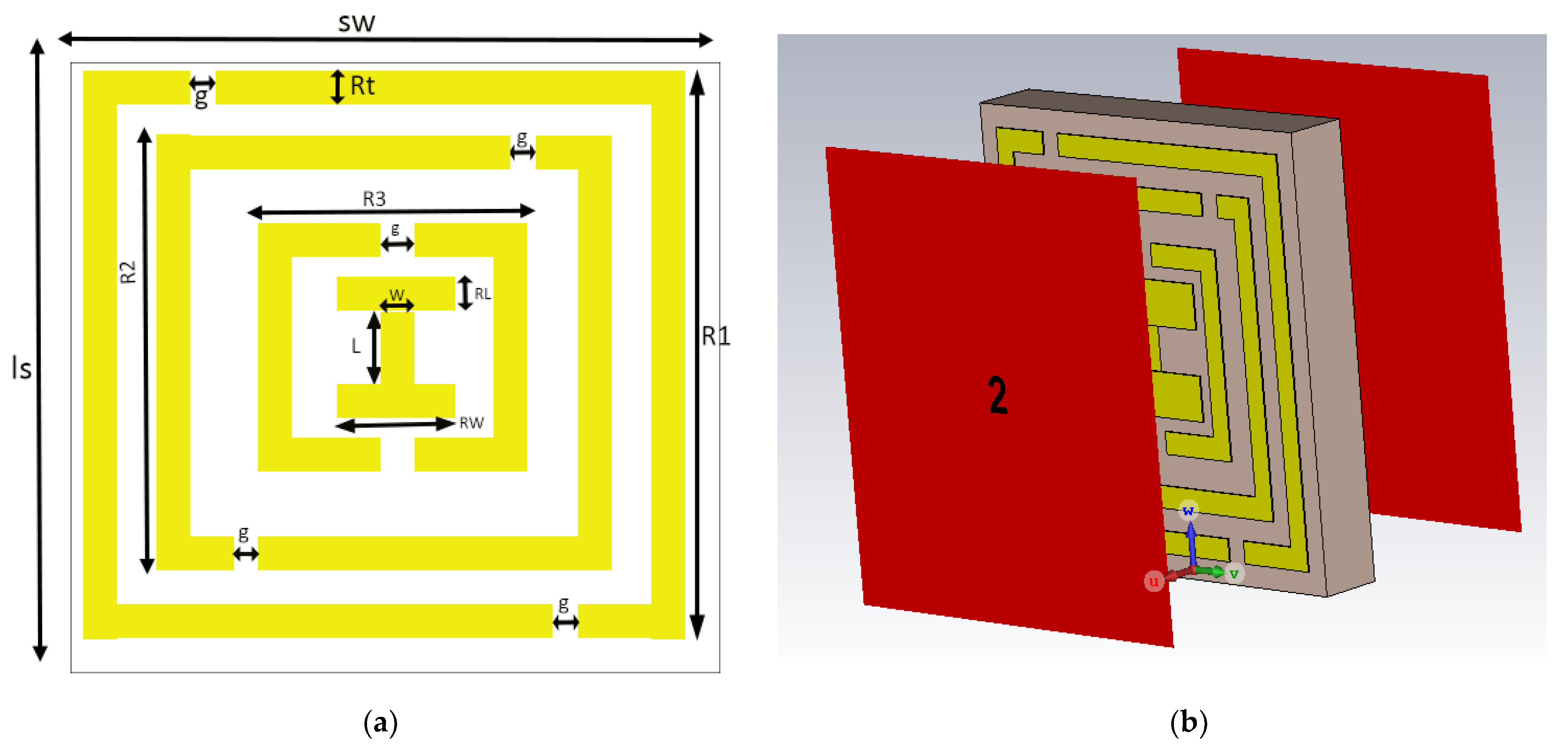
2. MeTM Unit Cell Geometry and Design

The geometrical configuration of the proposed ISMeTM unit cell and its simulated model are illustrated in Figure 1. A perfect electric conductor (PEC) is used for the metallic part and it is designed on the FR-4 dielectric substrate. The dielectric constant and loss tangent ( t a n δ ) of the FR-4 substrate material are 4.3 and 0.025, respectively. The thickness of the substrate and the thickness of the annealed copper used for the SRR are 1.6 mm and 0.035 mm, respectively. The primary function of splits in the ring resonators is to ensure that the inductance and capacitance interact with one another to determine the operating frequency. The unit cell’s total optimum size is 10 × 10 × 1.6 mm3 (sw × ls × sh). The parameters of the ISMeTM unit cell are presented in Table 1. The configuration and the comprehensive analysis of the MeTM properties is carried out using the Finite Integration Technique (FIT)-based electromagnetic CST simulator.

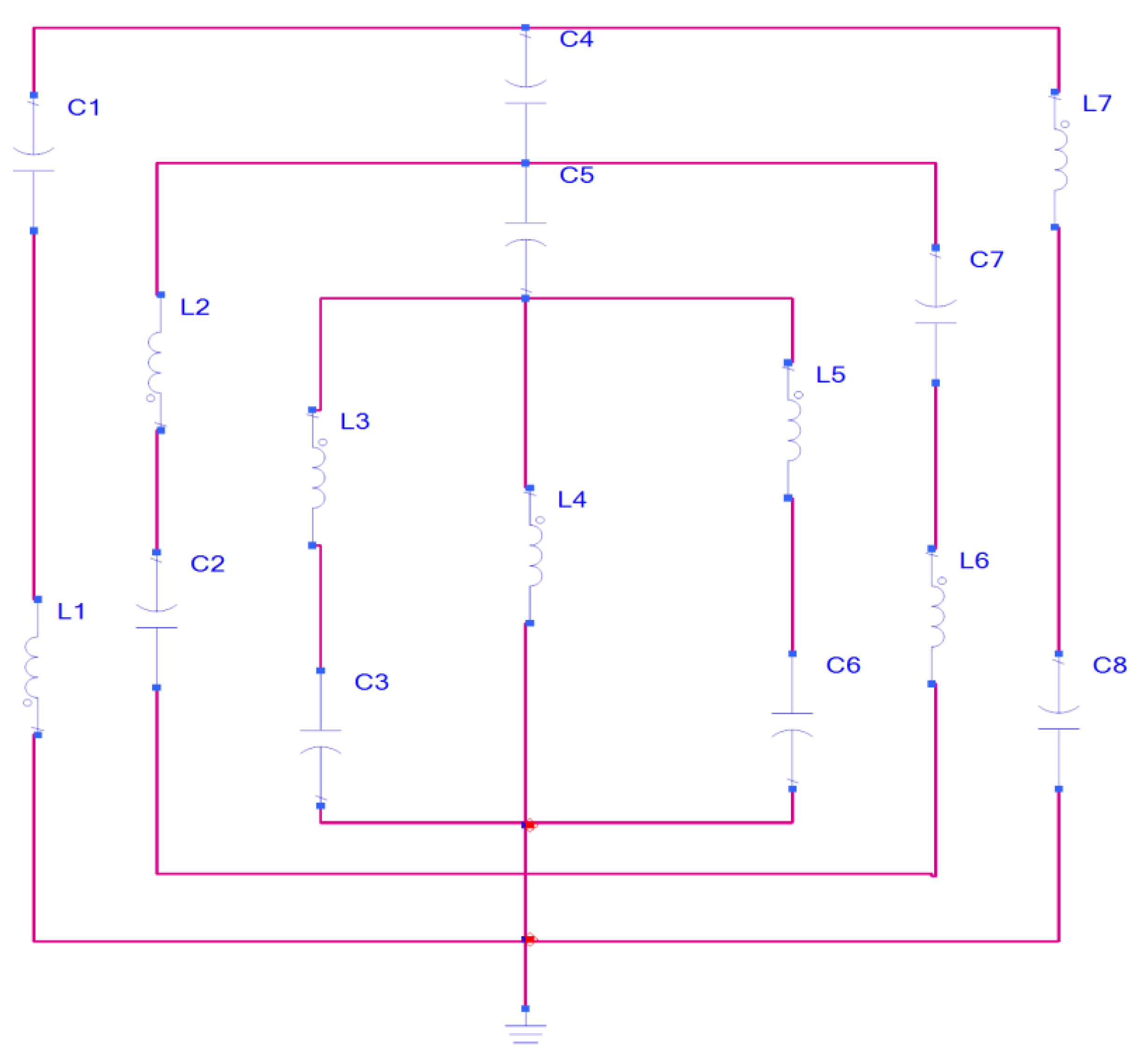
3. Theoretical Model and Equivalent Circuit of the ISMeTM

The proposed ISMeTM metal structure was designed on an FR-4 dielectric substrate layer. The time-varying EM field changes over time. The electron density engulfs the MeTM structure. Metal bars have been used to enhance the formation of a new distinct electromagnetic wave. The sensing response is handled by the metallic ring, while the split gap between the rings provides a strong electric field for the design. The transmission line approach was utilized to analyze the ISMeTM unit cell, which allows an individual strip or patch to duplicate an RLC series circuit. The passive LC circuit, which is connected to the resonance frequency. The equivalent circuit of the proposed ISMeTM is presented in Figure 2 which consists of the capacitance- and inductance-generating resonance on the proposed ISMeTM unit cell. The resonance frequency (fre) is expressed as [33,34]:
f r e = 1 2 π L E C E
where LE and CE represent the inductance and capacitance of the structure, respectively. Similarly, the split ring’s inner loop’s gap functions as a capacitor, while the metallic ring itself functions as an inductor. The electric resonance in the structure is created by interaction of the split ring and electric field while the interaction of magnetic fields with metallic loops during EM propagation in the structure causes magnetic resonance.
The total capacitance between the ring gap (Cg) can be defined as the capacitor of the parallel plate (Cpl) which compensate for the fringing field by extending the parameters plate width and thickness and is expressed as [35]:
C g = ε 0 h w g + ε 0 ( h + w + g )
C g = C f r i n g e + C p l = ε 0 [ ( h + g ) ( w + g ) g ]
where ε0 denotes the free space permittivity. h, w, and g represent the height, width, and gap of the ring, respectively. The inductance of the SSRR can be derived from the inductance of a rectangular loop [36]. By using a rectangular cross-sectional area with the conductor of a rectangular loop [37], we have:
L = μ 0 π {   ( h + w )   ln ( 2 h   w h c   + w c     ) h ln ( h + h 2 + w 2 ) w ln ( h + h 2 + w 2 ) h + w 2 + 2 h 2 + w 2 + 0.447 ( h c   + w c   ) }  
where h and w are the height and width of the rectangular loop, respectively. hc and wc denote the height and the width of the conductor’s cross section, respectively. The length and the width of the SSRR for the proposed ISMeTM structure R1 and Rt = R, and the weighting factor ρ e = 1 g / 4 R Equation (4) is used to analyze the perimeter of the SSRR. By rewriting Equation (4) we have,
L = ρ e μ 0 π   { 2 R ln ( 2 R 2 h c + w c ) 2 R ln   [ R ( 1 + 2 ) ] R + 2 R 2 + 0.447 ( h c + w c ) }
The parameter values for μ0 and ε0 are 8.854 × 10 12 F / m and 4 π × 10 7 H / m , respectively. In the equivalent circuit presented in Figure 2, C1, C2, C3, C4, C5, C6, C7, and C8 are the capacitors, and L1, L2, L3, L4, L5, L6, and L7 are the inductors. The circuit is designed using the ADS software.

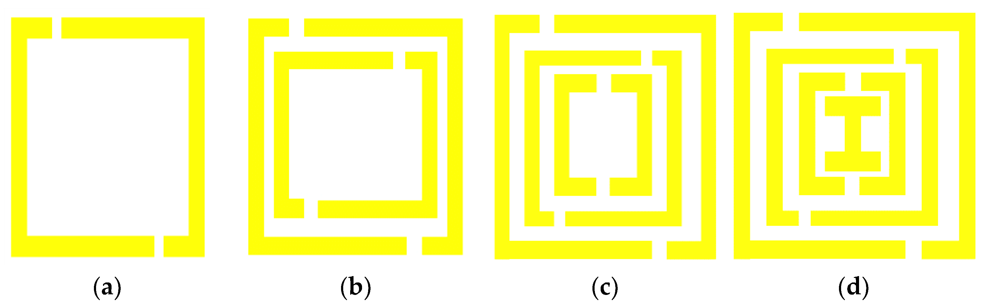
4. Design Methodology

In microwave communication application, various factors must be considered to provide multi-band operating frequencies. To increase the efficiency and effectiveness of the design for the proposed ISMeTM structure, the configuration is optimized using CST microwave studio. An iterative approach is used to obtain the response of the ISMeTM unit cell. Hence, modifying the resonance frequency is feasible by adjusting the dimensions and thickness of the substrate. However, because of the capacitance and inductance variation, some major parameters such as the length and width of the ring resonator, the ring gap between the rings, spilt gap and the ring length are responsible for producing the multi-band operating frequencies. The design steps for the proposed ISMeTM unit cell are shown in Figure 3. The reflection coefficient, transmission coefficient and permittivity for various design steps are shown in Figure 4a–c, respectively. In design step-a, double copper wire cut was introduced into the outer ring. From the S21 graph, it can be observed that the resonant frequencies are 6.4, 10.02 and 11.82 GHz. A second copper ring is introduced to the unit cell and four resonances at 6.23, 7.81, 10.17, 11.98 and 14.68 GHz are realized for design step-b. A third copper ring is introduced into the structure in design step-c. This design produces six resonances at 6.32, 7.81, 9.98, 11.46, 12.21 and 15.67 GHz. In design step-d (ISMeTM), an I-shaped metallic structure is introduced into the internal ring of the unit cell. Furthermore, seven resonances are obtained at 6.31, 7.79, 9.98, 10.82, 11.86, 13.36 and 15.5 GHz. The parameters for various design steps are summarized in Table 2.

5. Methodology for Extracting the Unit Cell’s Effective Medium Parameters

The effective parameters of the proposed ISMeTM unit cell can be determined by placing the structure between two waveguides (ports) such that the electromagnetic wave (EM) has magnetic field along the y-axis and electric field in the direction of the x-axis. Thus, the wave is propagated at the z-axis. This means that the first port acts as the reflecting signal’s transmitting port, while the second port acts as the signal’s receiving port. In addition, a tetrahedral mesh from frequency domain solver has been used for simulating the unit cell and array structure. The impedance has been set to 50 Ω. The operating frequency range is from 2 to 18 GHz. Figure 1b shows the simulation arrangement of the proposed ISMeTM unit cell inside the waveguide. The effective medium ratio depends on the unit cell dimension and the wavelength must be less the working wavelength. The reflection coefficient ( Γ ) can be expressed as [38]:
Γ = Z 0 1 Z 0 1  
The scattering parameters S11 and S21 can be calculated as follows:
S 11 = ( 1 Γ 2 ) Z 1 Γ 2 Z 2  
S 21 = ( 1 Z 2 ) Z 1 Γ 2 Z 2
from Equations (3) and (4),
V 1 = S 11 + S 21  
V 2 = S 21 S 11
where Z0, Z, S11 and S21 represent the impedance, the interface reflection coefficient, the reflection coefficient, and the transmission coefficient, respectively. The complex electric permittivity and complex magnetic permeability can be positive or negative in different combinations [39]. The Nicolson–Ross–Weir (NRW) method is adopted to determine the effective electric permittivity ( ε r ) , magnetic permeability ( μ r ) and relative refractive index ( η r ) of the proposed ISMeTM unit cell. The effective permittivity and permeability can be expressed as [40,41]:
ε r = 2 j π f s h × ( 1 V 1 1 + V 1 )
μ r = 2 j π f s h × ( 1 V 2 1 + V 2 )
The refractive index η r can be obtained as:
η r = 2 j π f s h × ( S 21 1 ) 2 S 11 2 ( S 21 + 1 ) 2 S 11 2
η = 1 k o s h { [ [ I n ( e j n k o s h ) ] ] + 2 m π j [ I n ( e j n k o s h ) ] }
where, k 0 = w c = 2 π f c and
e j n k o s h = S 21 1 S 11 Z 1 Z + 1
where f, k0, m, c and sh represent the operating frequency, the wave number, the branch index, the speed of light and the substrate thickness, respectively. Equations (6)–(13) have been used to analyze the scattering parameters of the ISMeTM unit cell and array.

6. ISMeTM Unit Cell Analysis

This section discusses the analysis of the proposed ISMeTM unit cell parameters. The Nicolson–Ross–Weir method has been used to extract the MeTM parameters. Detailed electromagnetic characteristic in terms of permeability, permittivity, relative index and the scattering parameters of the MeTM are shown in Figure 5. The CST Microwave Studio software is used to investigate the performance of the proposed ISMeTM. The analysis validates that the effective magnetic permittivity ( ε r ) is negative, the electric permeability ( μ r ) is positive, and relative refractive index ( η r ) is positive and negative within the same resonance frequency bands. As a result, these characteristics show that the proposed ISMeTM unit cell shows SNG metamaterial properties. The structure is designed to produce multi-band operation. Due to the compact nature of the ISMeTM, it can be utilized in antenna design for improving antenna performance. The proposed ISMeTM can also be used in satellite communications, WiFi devices, weather radar systems, surveillance etc.
The S-parameters and the effective parameters of the proposed ISMeTM unit cell are presented in Figure 5a,b, respectively. The obtained simulated S21 parameter of ISMeTM shows the resonance frequencies at 6.31, 7.79, 9.98, 10.82, 11.86, 13.36 and at 15.5 GHz in the C/X/Ku-bands.
Simulation of a time-dependent electromagnetic (EM) wave is the effective parameter utilized to measure the response of the MeTM cell design. Modifications in the geometric shape of the design can affect the permittivity and permeability characteristics. The real and imaginary values of the effective permittivity, effective permeability, and effective refractive index are shown in Figure 5b. From Figure 5a, it can be observed that the S21 shows the dips at 6.31, 7.79, 9.98, 10.82, 11.86, 13.36 and at 15.5 GHz. The 3-dB bands can be observed from the Figure 5a as 3.99–6.77 GHz (frequency band = 2.78 GHz, fractional BW = 51.67%), 7.07–8.27 GHz (frequency band = 1.2 GHz, fractional BW = 15.65%), 9.14–12.44 GHz (frequency band = 3.3 GHz, fractional BW = 30.58%), 13.01–13.70 GHz (frequency band = 0.69 GHz, fractional BW = 5.17%) and 15.04–15.83 GHz (frequency band = 0.79 GHz, fractional BW = 5.12%). The proposed structure shows the wideband operation and the maximum fractional bandwidth of 51.67% is achieved. Hence, the proposed structure can be used for wideband applications for different bands. From Figure 5b it can be observed that the ISMeTM produces the SNG characteristics for the frequency ranges 5.46–6.29, 11.6–11.8, 13.8–15 and 15.8–16.8 GHz. The analysis validates the following: the values of the effective electric permittivity ( ε r ) are negative; those of the magnetic permeability ( μ r ) are positive; and relative refractive index ( η r ) are positive and negative within the same resonance frequency bands. As a result, these characteristics show that the proposed ISMeTM unit cell shows the MeTM properties. The proposed ISMeTM is useful for medical devices, optical filters, remote aerospace applications, and electromagnetic cloaking etc.

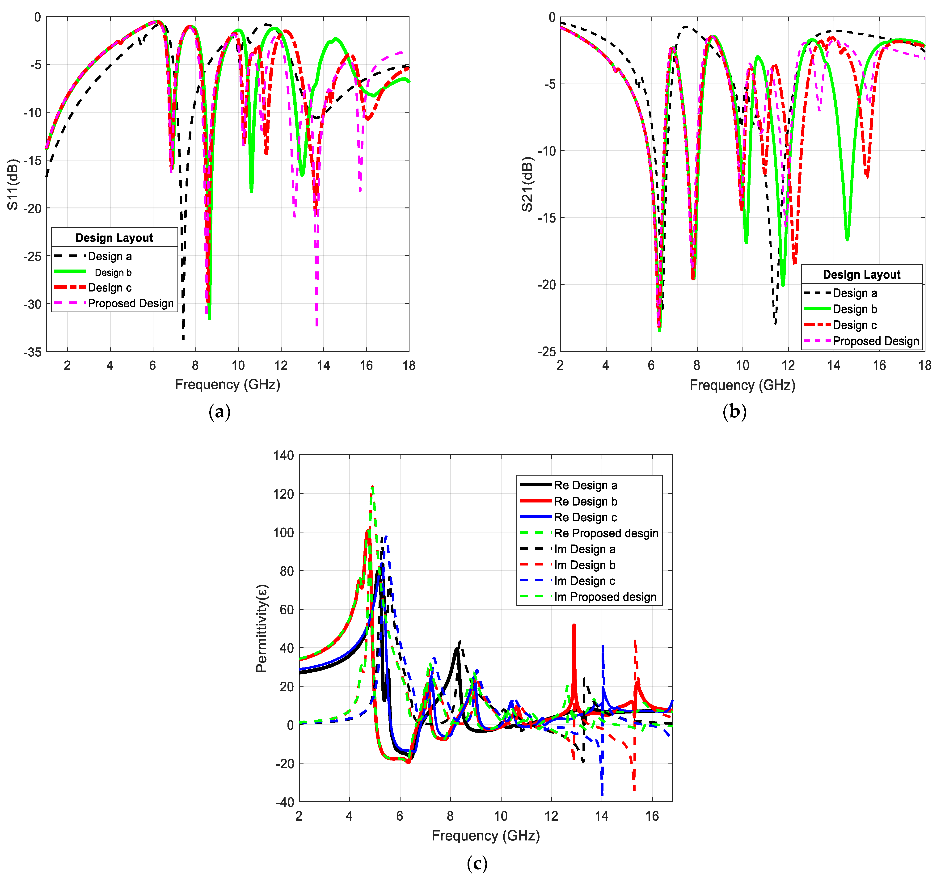
7. Result and Discussion

The parametric analysis for the ring gap (g) is carried out and presented in Figure 6. This analysis provides a suitable dimension for the ISMeTM design. It can be observed from Figure 6a that when the dimension of the ring gap (g) is varied, the operating band changes. It can be observed that for g = 0.5 mm and 1 mm the MeTM have the same number of resonance frequencies, while at g =1.5 mm and 2 mm the MeTM have five and six resonance frequencies, respectively. However, the MeTM has its best performance at the dimension of g = 0.5 mm. Furthermore, the variation of S21(dB) parameter with the variation of the ring gap (g) is displayed in Figure 6b. At g = 1 mm, 1.5 mm, and 2 mm, the ISMeTM has four and three resonance frequencies, respectively. Thus, when g is at 0.5 mm seven resonances are realized, making it the best dimension for optimal performance of the design.
The variation of the strip length (RL) of the unit cell is presented in Figure 6c. It is observed that the most suitable dimension of RL for the ISMeTM unit cell is 2 mm. Similarly, the strip width (W) of the unit cell is varied and presented in Figure 6d. It can be studied that at W = 0.5 mm the unit cell exhibits the optimum multi-band behavior. The variation of the S21 parameter with the dielectric constant and sh are shown in Figure 6e,f, respectively. From these figures, it can be observed that the center frequencies and the frequency bands can be modified by varying the dimensional parameters of the structure. The variation of permittivity and permeability with ls is shown in Figure 6g. The variation of permittivity and permeability with sh is shown in Figure 6h. From Figure 6g,h, it can be observed that the frequency band with SNG property and the values of permittivity and permeability can be varied by changing the dimensional parameters of the structure.

8. ISMeTM Array Analysis

The performance analysis of the ISMeTM unit cell’s 1 × 2 array, 2 × 2array, and 2 × 4 array configurations are presented in this section. The overall dimensions are 10 × 20 mm2, 20 × 20 mm2, and 20 × 40 mm2. To validate the results of the ISMeTM unit cell configuration, the three array configurations are investigated. The Nicolson–Ross–Weir (NRW) is used evaluate the array’s effective parameters.
The schematic diagram of 1 × 2 array, 2 × 2array, and 2 × 4 array configuration is presented in Figure 7. The arrays are formed by combining two-unit cells horizontally. The S11 and S21 parameters of the array configurations are simulated for the frequency range of 2–18 GHz, and the same approach is used to retrieve their effective parameters.
In Figure 8a, the S-parameters S11 (dB) and S21 (dB) are presented for the three array configurations. The 1 × 2 array shows the transmission dips at 6.23, 7.76, 10.10, 10.78, 11.72, 13.36 and 15.5 GHz, which are much closed to the ISMeTM unit cell. The 2 × 2 array structure generate transmission minima at frequencies 4.63, 6.05, 6.64, 7.44, 8.12 and 10.4 GHz. The dips of transmission coefficient |S21|of 2 × 4 array are observed at frequencies 4.69, 5.96, 6.52, 7.30, 7.84, 8.20 and 10.52 GHz. The permittivity of the array configurations is shown in Figure 8b. The SNG frequency ranges for 1 × 2 array; 2 × 2 array and 4 × 4 array are 5.46–6.29, 11.35–11.44, 13.2–14.9, 15.8–16.4; 5.44–6.31, 13.3–13.9, 14.6–15.8, 16.1–16.3 GHz and 5.46–6.28 GHz, 13.6–14.2 GHz, 14.9–15.3 GHz, 15.9–16.4 GHz, respectively. The parameters of various array configurations are summarized in Table 3. The frequency ranges for the parameters in the three array structures are nearly identical to the single unit cell, except variation for a few frequency bands. Due to mutual coupling effect between the array elements, there may be little variation in the array characteristics as compared to the unit cell [42]. In the proposed array, it can be observed that the array arrangements show similarities with the unit cell except for a few frequency bands that changes slightly which is due to the mutual coupling effect between the array elements. This occurs when two or more unit cells are vertically oriented on the y-axis. However, the arrays still exhibit multi-band properties.
The comparative analysis of the proposed ISMeTM is presented in Table 4. From this table, it can be observed that the proposed ISMeTM is low cost, compact in size and produces seven resonances. The proposed ISMeTM is suitable for multi-band C/X/Ku-band applications.

9. Conclusions

A novel ISMeTM unit cell using the SSRR along with its arrays has been designed, simulated and analyzed in this paper. The structure is designed using copper as its metal strip on a FR-4 dielectric substrate. The SSRRs along with an I-shaped patch is utilized for designing the ISMeTM. The detailed theory and equivalent circuit of the ISMeTM are presented. The proposed structure produced multiple resonances and SNG behavior. The proposed ISMeTM is suitable for use in multi-band microwave applications including C band, X band and Ku band. The design and analysis of 1 × 2, 2 × 2, and 2 × 4 array structure of the proposed ISMeTM unit cell are also investigated. The proposed low-cost and compact ISMeTM are suitable for multi-band satellite communication systems, radar applications, sub-6 GHz 5G applications, ultra-wideband applications, etc.

Author Contributions

Conceptualization, B.A., P.K. and T.A.; methodology, B.A., P.K. and T.A.; software, B.A.; validation, B.A., P.K. and T.A.; writing—B.A. and P.K.; writing—review and editing, B.A., P.K. and T.A.; supervision, P.K. and T.A. All authors have read and agreed to the published version of the manuscript.

Funding

This research was funded by Eskom.

Institutional Review Board Statement

Not applicable.

Informed Consent Statement

Not applicable.

Data Availability Statement

Not applicable.

Conflicts of Interest

The authors declare no conflict of interest.

References

  1. Ali, T.; Subhash, B.K.; Pathan, S.; Biradar, R.C. A compact decogonal-shaped UWB monopole planar antenna with truncated ground plane. Microw. Opt. Technol. Lett. 2018, 30, 2937–2944. [Google Scholar] [CrossRef]
  2. Mandel’shtam, L.I. Group velocity in crystal lattice. Zh. Eksp. Teor. Fiz. 1945, 15, 475–478. [Google Scholar]
  3. Veselago, V.G. The electrodynamics of substances with simultaneously negative values of ε and µ. Sov. Phy. Usp. 1968, 10, 509–514. [Google Scholar] [CrossRef]
  4. Pendry, J.B.; Holden, A.J.; Stewart, W.J.; Youngs, I. Extremely low frequency plasmons in metallic meostructure. Phys. Rev. Lett. 1996, 76, 4773. [Google Scholar] [CrossRef] [Green Version]
  5. Pendry, J.B.; Holden, A.J.; Robbins, D.J.; Stewart, W.J. Magnetism from conductors and enhanced nonlinear phenomena. IEEE Trans. Microw. Theory. Tech. 1999, 47, 2075–2084. [Google Scholar] [CrossRef] [Green Version]
  6. Smith, D.R.; Willie, W.J.; Vier, D.C.; Nemat-Nasser, S.C.; Schultz, S. Composite medium with simultaneously negative permeability and permittivity. Phy. Rev. Lett. 2000, 84, 4184. [Google Scholar] [CrossRef] [Green Version]
  7. Iyer, A.K.; Eleftheriades, G.V. Negative refractive index metamaterials supporting 2-D waves. IEEE MTT-S Int. Microw. Symp. Digest. 2002, 2, 1067–1070. [Google Scholar]
  8. Caloz, C.; Itoh, T. Transmission line approach of left-handed (LH) material and microstrip implementation of an artificial LH transmission line. IEEE Trans. Antennas Propag. 2004, 52, 1159–1166. [Google Scholar] [CrossRef]
  9. Sreekanth, K.V.; ElKabbash, M.; Alapan, Y.; Rasheed, A.R.; Gurkan, U.A.; Strangi, G. A multiband perfect absorber based on hyperbolic metamaterials. Sci. Rep. 2016, 6, 1–8. [Google Scholar]
  10. Huang, C.; Zhang, J.; Cheng, Q.; Cui, T. Multi-band tunable asymmetric transmission of linearly polarized electromagnetic waves achieved by active chiral metamaterial. In Proceedings of the 2019 Photonics & Electromagnetics Research Symposium-Fall (PIERS-Fall), Xiamen, China, 17–20 December 2019. [Google Scholar]
  11. Wang, M.; Yang, Z.; Wu, J.; Bao, J.; Lui, J.; Cai, L.; Dang, T.; Zheng, H.; Li, E. Investigation of SAR reduction using flexible antenna with metamaterial structure in wireless body area network. IEEE Trans Antenna Propag. 2018, 66, 3076–3086. [Google Scholar] [CrossRef]
  12. Ameen, M.; Chaudhary, R.K. Metamaterial-based circularly polarized antenna employing ENG-TL with enhanced bandwidth for WLAN applications. Electro. Lett. 2018, 54, 1152–1154. [Google Scholar] [CrossRef]
  13. David, R.M.; Aw, M.S.; Ali, T.; Kumar, P. A multiband antenna stacked with novel metamaterial SCSRR and CSSRR for WiMAX/WLAN applications. Micromachines 2021, 12, 113. [Google Scholar] [CrossRef] [PubMed]
  14. Srinivasan, K.; Ali, N.B.; Trabelsi, Y.; Mani Rajan, M.S.; Kanzari, M.M. Design of a modified single-negative metamaterial structure for sensing application. Optik 2019, 180, 924–993. [Google Scholar] [CrossRef]
  15. Chen, H.; Chen, Z.; Yang, H.; Wen, L.; Yi, Z.; Zhou, Z.; Dai, B.; Zhang, J.; Wu, X.; Wu, P. Multi-mode surface plasmon resonance absorber based on dart-type single- layer graphene. RSC Adv. 2022, 12, 7821–7829. [Google Scholar] [CrossRef]
  16. Hasan, M.M.; Faruque, M.R.I.; Islam, M.T. Dual band metamaterial antenna for LTE/Bluetooth/WIMAX system. Sci. Rep. 2018, 8, 1–17. [Google Scholar] [CrossRef] [PubMed] [Green Version]
  17. Islam, S.S.; Faruque, M.R.I.; Islam, M.T. An object independent ENZ metamaterial based wideband electromagnetic cloak. Sci. Rep. 2016, 6, 1–10. [Google Scholar] [CrossRef] [Green Version]
  18. Alex-Amor, A.; Palomares-Caballero, A.; Molero, C. 3-D metamaterials: Trends on applied designs, computational methods and fabrication techniques. Electronics 2022, 11, 410. [Google Scholar] [CrossRef]
  19. Alam, J.; Faruque, M.R.I.; Islam, M.T. Labyrinth double split open loop resonator based bandpass filter design for S, C and X-band application. J. Phys. D. App. Phys. 2018, 51, 265102. [Google Scholar] [CrossRef]
  20. Zheng, Z.; Zheng, Y.; Luo, Y.; Yi, Z.; Zhang, J.; Liu, Z.; Yang, W.; Yu, Y.; Wu, X.; Wu, P. A switchable terahertz device combining ultra-wideband absorption and ultra-wideband complete reflection. Phys. Chem. Chem. Phys. 2022, 24, 2527–2533. [Google Scholar] [CrossRef]
  21. Vendik, I.B.; Vendik, O.G. Metamaterial and their application in microwaves: A review. Tech. Phys. 2013, 58, 1–24. [Google Scholar] [CrossRef]
  22. Benosman, H.; Hacene, N.B. Design and Simulation of Double “S” Shaped Metamaterial. Int. J. Compt. Sci. Iss. 2012, 9, 1694–1814. [Google Scholar]
  23. Aznabet, M.; El Mrabet, O.; Floc’h, J.M.; Falcone, F.; Drissi, M.A. A coplanar waveguide-fed printed antenna with complementary split ring resonator for wireless communication systems. Waves. Rand. Comp. Media. 2015, 25, 43–51. [Google Scholar] [CrossRef]
  24. Mallik, A.; Kundu, S.; Goni, M.O. Design of a novel two-rectangular U-shaped negative metamaterial. In Proceedings of the International Conference on Informatics, Electronics and Vision IEEE, Dhaka, Bangladesh, 17 May 2013. [Google Scholar]
  25. Alam, M.J.; Ahamed, E.; Faruque, M.R.I.M.; Hossain, J.; Islam, M.T. Aztec shape metamaterial-based bandpass filter for C, X and Ku-band applications. IOP Conf. Ser. Ear. Enviro. Sci. 2019, 228, 012019. [Google Scholar] [CrossRef]
  26. Ekmekci, E.; Sayan, G.T. Investigation of effective permittivity and permeability for a novel V-shaped metamaterial using S-parameters. In Proceedings of the 5th International Conference on Electrical and Electronics Engineering, Bursa, Turkey, 5–9 December 2007. [Google Scholar]
  27. Jain, P.; Thourwal, A.; Sardana, N.; Kumar, S.; Gupta, N.; Singh, A.K. I-shaped metamaterial antenna for X-band applications. In Proceedings of the Progress in Electromagnetics Research Symposium-Spring (PIERS), Petersburg, Russia, 22 May 2017. [Google Scholar]
  28. Dhouibi, A.; Burokur, S.N.; Lustrac, A.; Priou, A. Study and analysis of an electric Z-shaped meta-atom. Advan. Electromag. 2012, 1, 64–70. [Google Scholar] [CrossRef] [Green Version]
  29. Tamim, A.M.; Faruque, M.R.I.; Alam, M.J.; Islam, S.S.; Islam, M.T. Split ring resonator loaded horizontally inverse double L-shaped metamaterial for C-, X- and Ku-Band Microwave applications. Res. Phys. 2019, 12, 2112–2122. [Google Scholar] [CrossRef]
  30. Hossain, M.J.; Faruque, A.M.I.; Islam, M.T.; Islam, S.S. An effective medium ratio obeying meta-atom for multiband applications. Bull. Pol. Acad. Sci. Tech. Sci. 2019, 65, 2112–2122. [Google Scholar] [CrossRef] [Green Version]
  31. Islam, S.S.; Faruque, M.R.I.; Islam, M.T. The design and analysis of a novel H-shaped metamaterial for multi-band microwave applications. Materials 2014, 7, 4994–5011. [Google Scholar] [CrossRef] [Green Version]
  32. Siddiky, A.M.; Faruque, M.R.I.; Islam, M.T.; Abdullah, S.; Khandaker, M.U. Inverse double-C shaped square split ring resonator-based metamaterial with multi-resonant frequencies for satellite band applications. Res. Phys. 2020, 19, 103454. [Google Scholar]
  33. Sydoruk, O.; Tatartschuk, E.; Shamonia, E.; Solymar, L. Analytical formulation for the resonant frequency of split rings. J. Appl. Phys. 2009, 5, 014903. [Google Scholar] [CrossRef]
  34. Rinard, G.A.; Eaton, G.R. Biomedical EPR-Part B: Methodology, Instrumentation, and Dynamics; Springer Science & Business Media: New York, NY, USA, 2005; pp. 19–52. [Google Scholar]
  35. Grover, F.W. Inductance Calculations: Working Formulas and Tables; Courier Corporation, Instrument Society of America, Research Triangle Park: Pittsburgh, PA, USA, 1981. [Google Scholar]
  36. Shatz, L.F.; Christensen, C.W. Numerical inductance calculations based on its principles. PLoS ONE 2014, 11, e111643. [Google Scholar]
  37. Chen, X.; Grzegorczyk, T.M.; Pacheco, B.; Wu, J.; Kong, J.A. Robust method to retrieve the constitutive effective parameters of metamaterials. Phys. Rev. E 2014, 70, 1–7. [Google Scholar] [CrossRef] [PubMed] [Green Version]
  38. Rothwell, E.J.; Frasch, J.L.; Ellison, S.M.; Chahal, P.; Ouedraogo, R.O. Analysis of the Nicolson-Ross-Weir method for characterizing the electromagnetic properties of engineered materials. Prog. Electromag. Res. 2016, 157, 32–47. [Google Scholar] [CrossRef] [Green Version]
  39. Gric, T.; Nickelson, L.; Asmontas, S. Electrodynamical characteristic particularity of open metamaterial square and circular waveguides. Prog. Electromag. Res. 2010, 109, 361–379. [Google Scholar] [CrossRef] [Green Version]
  40. Luukkonen, O.; Maslovski, S.I.; Tretyakov, S.A. A stepwise Nicolson-Ross-Wier-based material parameter extraction method. IEEE Ant. Wirel. Propag. Lett. 2011, 10, 1295–1298. [Google Scholar] [CrossRef]
  41. Afsar, S.U.; Faruque, M.R.I.; Hossain, M.J.; Khandaker, M.U.; Osman, H.; Alamri, S. Modified Hexagonal split ring resonator based on epsilion-negative metamaterial for triple-band satellite communication. Micromachines 2021, 12, 878. [Google Scholar] [CrossRef]
  42. Moniruzzaman, M.; Islam, M.T.; Islam, M.R.; Misran, N.; Samsuzzaman, M. Coupled ring split resonator (CR-SRR) based epsilon negative metamaterial for multiband wireless communications with high effective medium ratio. Res. Phys. 2020, 18, 103248. [Google Scholar] [CrossRef]
Figure 1. Proposed ISMeTM: (a) unit cell configuration; (b) simulated model.
Crystals 12 00559 g001
Figure 2. The equivalent circuit of the proposed ISMeTM structure.
Crystals 12 00559 g002
Figure 3. Design steps for the proposed ISMeTM unit cell: (a) design step-a; (b) design step-b; (c) design step-c; (d) design step-d (ISMeTM).
Crystals 12 00559 g003
Figure 4. Reflection and transmission parameters of various configurations: (a) S11; (b) S21, (c) permittivity.
Crystals 12 00559 g004
Figure 5. S-parameters and effective parameters of the ISMeTM: (a) S-parameters; (b) effective parameters.
Crystals 12 00559 g005
Figure 6. ISMeTM unit cell parameters: (a) variation of S11 with g; (b) variation of S21 with g; (c) variation of S11 with RL; (d) variation of S11 with W; (e) variation of S21 with dielectric constant of the substrate; (f) variation of S21 with sh; (g) variation of permittivity and permeability with ls; (h) variation of permittivity and permeability with sh.
Crystals 12 00559 g006aCrystals 12 00559 g006b
Figure 7. Schematic diagram of ISMeTM arrays: (a) geometry of 1 × 2 array; (b) simulated model of 1 × 2 array; (c) geometry of 2 × 2 array; (d) simulated model of 2 × 2 array; (e) geometry of 2 × 4 array; (f) simulated model of 2 × 4 array.
Crystals 12 00559 g007
Figure 8. Parameters of array configurations: (a) S-parameters; (b) permittivity; (c) permeability; (d) refractive index.
Crystals 12 00559 g008
Table 1. Parameter of the ISMeTM unit cell.
ParameterDimension (mm)ParameterDimension (mm)
sw10Rw1.25
ls10L1
R19W0.5
R24g0.5
R32.8sh1.6
Rt0.5ch0.035
Rl2tw0.5
Table 2. Parameters of various design steps.
Design LayoutFrequency (GHz)S21 (dB)
Design a6.4, 10.02, 11.82−21.99, −8.23, −22.96
Design b6.23, 7.81, 10.17, 11.98, 14.68−23.12, −19.53, −16.81, −19.97,
−16.41
Design c6.32, 7.81, 9.98, 11.46, 12.21, 15.67−18.15, −16.14, −11.75, −7.34,
−19.13, 8.32
Proposed design (ISMeTM)6.31, 7.79, 9.98, 10.82, 11.86, 13.36, 15.5−22.96, −18.89, −13.47, −8.64,
−15.49, −6.87, −6.45
Table 3. Parameters of ISMeTM unit cell, ISMeTM 1X2 array, ISMeTM 2X2 array and ISMeTM 2X4 array.
ConfigurationSNG Freq. Range (GHz)S21 Dips Frequencies (GHz)S21 (dB)
ISMeTM unit cell5.46–6.29, 11.6–11.8,
13.8–15,15.8–16.8
6.31, 7.79, 9.98, 10.82, 11.86, 13.36, 15.5−22.96, −18.89, −13.47,
−8.64, −15.49, −6.87,
−6.45
ISMeTM 1 × 2 array5.46–6.29, 11.35–11.44,
13.2–14.9, 15.8–16.4
6.23, 7.76, 10.10, 10.78, 11.72, 13.36, 15.5−22.40, −17.91, −11.64,
−9.84, −17.16, −4.56,
−6.35
ISMeTM 2 × 2 array5.44–6.31, 13.3–13.9,
14.6–15.8, 16.1–16.3
4.63, 6.05, 6.64, 7.44, 8.12, 10.4−8.33, −18.46, −13.97,
−14.67, −14.04, −14.21
ISMeTM 2 × 4 array5.46–6.28, 13.6–14.2,
14.9–15.3, 15.9–16.4
4.69, 5.96, 6.52, 7.30 7.84, 8.20, 10.52−8.67, −13.57, −17.35,
−12.33, −16.41, −16.49,
−16.76
Table 4. Comparative analysis of the proposed ISMeTM with the structures in literature.
RefDimension
(mm)2
ShapeSubstrateBandResonance Frequency (GHz)
[22]4 × 4Double SFR-4Ku-1
[23]30 × 22 × 0.8CSRRRoger Duroid TM 5880C1
[24]25 × 25 × 1U-shapedGlassC1
[25]12 × 11 × 1.6AztecFR-4C, X, Ku4
[26]5 × 5 × 0.25V-shapedFused QuartzX1
[27]12.5 × 12.5I-shapedFR-4X1
[28]10 × 10Inverse double LRogers RT 5880C, X, Ku4
[30]12 × 12 × 1.635C-shapedRogers RT 6010S, C, X, Ku4
[31]30 × 30H-shapedFR-4S, C, X, Ku4
[32]9 × 9 × 1.6Double CFR-4S, C, X, Ku5
Proposed10 × 10 × 1.6I-shapedFR-4C, X, Ku7
Publisher’s Note: MDPI stays neutral with regard to jurisdictional claims in published maps and institutional affiliations.

