Abstract
A good understanding of the chemical disorder in silicon carbide (SiC) after ion irradiation is crucial for evaluating structural stability in both semiconductor and nuclear power systems. In this study, 6H-SiC single-crystal was irradiated with 500 keV He and 2.5 MeV Fe ions at room temperature, followed by annealing at 1500 °C for 2 h. The chemical disorders were investigated by electron energy-loss spectroscopy with the transmission electron microscopy at 200 kV. Facetted voids were found in the end region of the damaged layer. Compared with the substrate region, the Si at.% was lower, while the values of C and O at.% were higher, in particular in inner voids. SiCOx (x < 1) bonds at the inner surface of the voids were detected. The energy losses of Si, C edges shifted to be lower in the damaged layer. The possible reason is discussed, and the research results will be used for understanding the ion irradiation-induced damage in SiC.
1. Introduction
As the semiconductor material with a direct band-gap of 3.0 eV, 6H-SiC is regarded as a promising material used in laser diodes, microwave, optoelectronic, and high frequency devices [1,2]. In order to obtain electrical, optical, or magnetic selective-area doping in the structures of SiC devices, ion implantation has been widely used. It is well known that ion implantation usually introduces lattice defects into materials that can not only affect structural stability, but also enhance oxidation and corrosion rate. Moreover, the formation of homo-nuclear bonds (such as Si-Si and C-C bonds) can degrade the device’s performance [3,4,5,6,7,8,9,10]. For example, the lattice defects can increase light absorption coefficient and leakage current, accompanied by the decrease of band-gap [3,4]. Meanwhile, the chemical disorder can affect the interaction between oxygen and silicon carbide. Makhtari et al. found the enhanced oxidation rate in SiC after Si+, P+ and Al+ ions irradiation [11]. It is attributed to the breakdown of the Si-C bonds induced by cascade collision and led to the increase in chemical reactivity. Similarly, Kondo et al. argued that the corrosion rates at the irradiated regions increased with increasing dose [12]. They regarded that a reduction of the oxygen diffusion barrier at the sample surface due to irradiation damage can explain the acceleration of the SiC corrosion rates. Xi et al. used molecular dynamics simulations to investigate the influence of implantation-induced point defects on SiC oxidation and found the phenomenon of defect-accelerated oxidation regardless of the type of defects [13]. Therefore, it is important to study the chemical disorder in SiC under ion irradiation.
Nowadays, irradiation damage in SiC caused by different ions has been widely investigated. It has been reported that the formation of the diluted magnetic semiconductor in 6H-SiC single crystals implanted with Fe ions [14]. The concentration of Fe atoms is important for forming the diluted magnetic semiconductor [15]. Recently, we also observed ferromagnetic behavior in Fe-implanted GaN at room temperature (RT) [16]. The saturation magnetization decreased with increasing interstitial-type defects, which were produced by Fe implantation. Therefore, it is important to reduce lattice disorder during Fe implantation. For example, the decrease of Fe fluence is one of the choices. As we know, voids can trap metal impurities in Si, such as Cu and Au [17,18]. Voids would be formed by He implantation followed by annealing [19]. Therefore, in this study, 6H-SiC single crystal was irradiated with both He and Fe ions at RT followed by 1500 °C annealing.
Raman spectroscopy and energy-dispersive X-ray spectroscopy (EDS) are experimental techniques well known for their ability to characterize chemical bonds and element distribution, respectively. Raman spectroscopy revealed that Si-C bonds were broken by cascade collision, resulting in the formation of Si-Si and C-C bonds in the amorphous SiC [20,21,22]. The phase transformation from a single crystal to an amorphous phase occurs when radiation damage is larger than 0.3 dpa at room temperature [23]. Single crystalline 6H-SiC has several active modes in Raman spectra based on group theory selection rules [20]. The first-order Raman bands of E2 (TO) at 767 cm−1, E1(TO) at 789 cm−1, and A1(LO) at 967 cm−1, as well as second-order Raman bands attributed E2(TA) at 266 cm−1, and A1(LA) at 504−1 cm−1 and 513 cm−1 are activated. In the amorphous layer, the feature peaks of crystalline SiC are absent, except for two broad peaks at 1301 cm−1 and 1562 cm−1, corresponding to disordered diamond and graphite, respectively [20]. Our previous work investigated elemental evolution in SiC after He irradiations at an ultra-high fluence of 7.3 × 10¹⁷/cm2 [24]. We observed carbon enriched phases in the damaged layer, particularly in the vicinity of bubbles. In addition, we also observed that C atoms prefer to agglomerate on grain boundaries after ion irradiation, increasing the bubble nucleation in interior grains, as compared to He-implanted single crystalline SiC [25]. Although Raman spectroscopy is a non-destructive method to measure chemical bonds, the spatial resolution is limited because the laser beam diameter is more than 1 μm. In addition, the depth resolution is also limited. Usually, the penetration depth of the laser beam can reach several tens micrometers, which is far more than the depth of irradiation-induced lattice defects. As a result, the signal produced by the substrate is intense, which can have a sever influence on signals of lattice defects. The reduction of the substrate signal requires a lower excited wavelength, which will, in turn, lead to a decrease in signal intensity. Obtaining a better signal-to-noise ratio requires more integration time. EDS can be used for the chemical analysis but not chemical bonds. In addition, EDX prefers analyzing heavy elements. Electron energy-loss spectroscopy (EELS) has a high spatial resolution and can measure chemical bonds and element concentration qualitatively. Therefore, EELS is useful equipment for characterizing chemical disorders [26,27,28,29]. In this study, stoichiometric silicon carbide in the damaged region was investigated by EELS. The results are compared to the previous reports of ion-irradiated SiC. The study provides important experimental data for a better understanding of the fundamental defect evolution in SiC, which may lead to improvement of the fabrication of SiC devices.
2. Materials and Methods
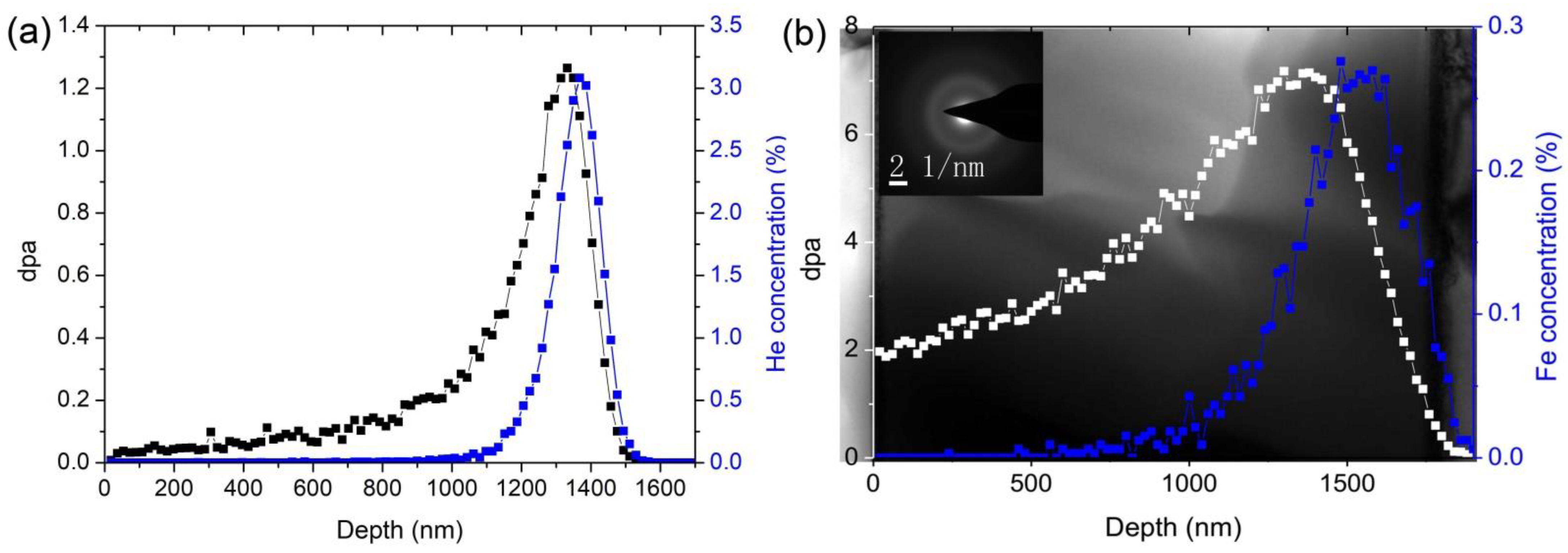
In the present study, the experimental material is an n-type SiC <0001>Si orientation with 0.3 μm in thickness, provided by HF-Kejing Company, Hefei, China. The wafer was cut into 10 × 10 mm2 for the ion irradiations at room temperature. He and Fe ion irradiation were consecutively injected. The irradiation experiment with 500 keV He2+ ions to a fluence of 5 × 10¹⁶/cm2 followed by 2.5 MeV Fe10+ ions to a fluence of 1 × 10¹⁶/cm2 were performed on a 320-kV high-voltage platform equipped with electron cyclotron resonance (ECR) ion sources in the Institute of Modern Physics, Chinese Academy of Sciences (CAS) [30,31]. ECR can provide higher charges states with higher intensities compared to some other ion resources [32], i.e., Penning ion source. The beam rates of He2+ and Fe10+ were 1 × 10¹³ ions/cm2.s and 4 × 10¹¹ ions/cm2.s, respectively. The beam was rastered using an electrostatic scanner in horizontal and vertical directions. The beam size was 17 × 17 mm2, which is larger than the size of the wafer. The vacuum system was better than 1 × 10⁻⁴ Pa during the ion irradiation. Figure 1 shows the distributions of the damage level in dpa induced by He to a fluence of 5 × 10¹⁶/cm2 and Fe to a fluence of 1 × 10¹⁶/cm2 irradiation simulated by the Monte-Carlo code Stopping and Range of Ions in Matter (SRIM-2008) with quick calculation using the displacement energies of Si = 35 eV, C = 20 eV and density of 3.21 g/cm3 [33]. The radiation dose was far larger than the threshold condition for forming amorphization, as shown in Figure 1b, where the amorphous layer started from the surface to a depth over 1700 nm. Post-irradiation, the sample was annealed at 1500 °C for 2 h, while recrystallization occurred. Chemical analyses were carried out by a transmission electron microscopy FEI Tecnai G20 equipped with a Gatan EnfiniumTM SE 976 energy filter with an energy resolution of 0.9 eV at the zero-loss peak. To avoid electron beam damage, a probe current of ~0.02 nA was used along with a convergence semi-angle of 8.8 mrad and a collection semi-angle of 18 mrad. The adsorption edges chosen for analysis were the Si-L, C-K and O-K edges. The TEM was operated at 200 kV. Cross-sectional transmission electron microscopy (XTEM) sample was prepared by mechanical thinning, followed by Ar ion milling, as described in Ref. [34].
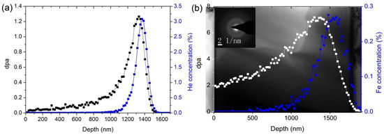
Figure 1.
The depth profiles of displacement per atoms (dpa) and atomic layer deposition (%) in 6H-SiC induced by (a) 500 keV He2+ irradiation to a fluence of 5 × 10¹⁶/cm2 and (b) 2.5 MeV Fe10+ irradiation to a fluence of 1 × 10¹⁶/cm2, containing the XTEM bright field micrograph of 6H-SiC irradiated with 2.5 MeV Fe10+ ions. The selected area electron diffraction pattern shows a diffuse ring in the damaged layer.
3. Results and Discussions
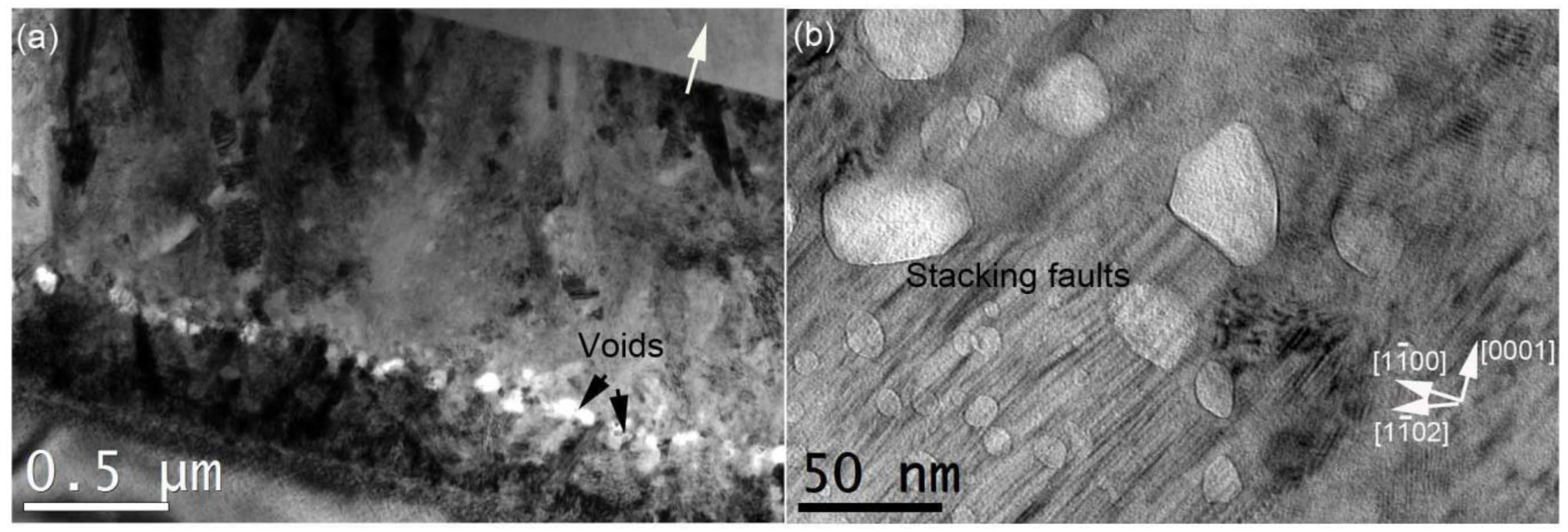
After the annealing at 1500 °C for 2 h, the phase transformation of amorphous SiC to crystalline SiC occurred. Many extended defects were formed in the recrystallized layer. In addition, it was possible that the implanted He atoms were released from bubbles, while voids formed inside the sample [35]. Figure 2a shows the recrystallized structure, where columnar grains and voids were clearly observed, exhibiting black and white contrasts, respectively. In our previous reports, stacking faults and nano-twinned 3C-SiC gains were also formed [36]. Voids present polygonal shapes due to different surface energies [37]. In detail, voids prefer to grow along the low surface energy. Kondo et al. investigated void morphology in 6H-SiC single crystals irradiated with neutron at 1400 °C + 100 °C, and found irregular icosahedrons truncated with six {100}, twelve {103}, one smaller top-basal, and one larger bottom-basal planes [38]. However, stacking faults can affect the morphology of voids. Figure 2b shows the preferential growth plane that is perpendicular to the plane of stacking faults. Some small and round voids were formed in the stacking faults. Large facetted voids were found at the periphery of the stacking faults. It is attributed to the influence of stacking faults that provide fast migration routes for silicon interstitials, leaving lots of vacancies around them [39]. These vacancies would migrate and coalesce into voids via Ostwald ripening mechanism. The same phenomenon was also found in ferritic/martensitic steels implanted with high fluences of He ions at over 400 °C, where bubbles were usually formed along dislocations [40,41,42,43]. Void growth depends on the surface energy, vacancy concentration and migration energy of vacancies [44]. It needs further study via computer simulation.
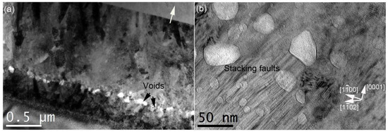
Figure 2.
XTEM bright-field image showing the recrystallization structure of He and Fe co-irradiated 6H-SiC at RT followed by 1500 °C annealing, (a) a general view and (b) a magnified image showing voids in the tail region of the recrystallization layer. The white arrow indicates the normal direction of the sample surface.
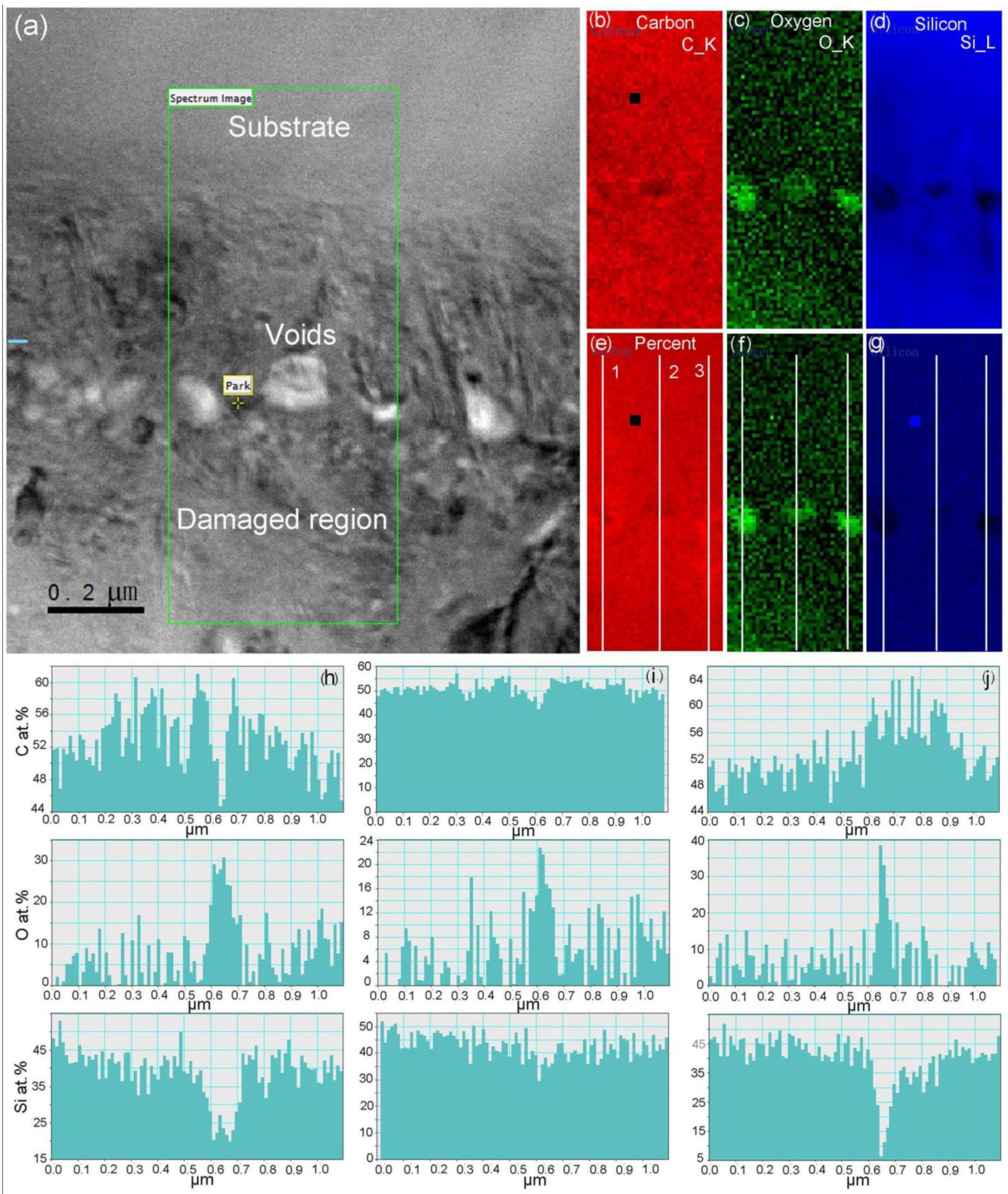
Carbon, oxygen, and silicon distributions were investigated by EELS, as shown in Figure 3. The 1109 × 678 nm2 scanned zone contains the substrate, the voids, and the damaged region. The spatial point is 21 × 21 nm2. C_K, O_K, and Si_L absorption edges were presented in Figure 3b–d, respectively. The O signal is significantly stronger at the voids, indicating oxygen-enriched inside the voids. On the contrary, the Si signal is lower, demonstrating a lower concentration of silicon atoms. Note that there is a square-shape feature in Figure 3b,d, where it looks like Si-rich and C-depleted. The signal suddenly changed. This is a noise point during the EELS measurement. We did another region analysis, and no noise points were observed (not shown). Atomic percentages were shown in Figure 3e–g. C, O and Si at.% taken from three lines are presented in Figure 3h–j. The direction of the line is from the substrate to the damage region. In the substrate, the contents of C, O, Si are in the range of 50 at.% to 52 at.%, 0 at.% to 8 at.%, 40 at.% to 48 at.%, respectively. At the voids, the contents of C, O, Si are in the range of 44 at.% to 54 at.%, 22 at.% to 35 at.%, 6 at.% to 30 at.%, respectively. In the damaged region, the contents of C, O, Si are in the range of 46 at.% to 64 at.%, 0 at.% to 15 at.%, 35 at.% to 45 at.%. It can be seen that the C atomic concentration is over 50 at.%, in particular at the periphery of voids. The oxygen atomic concentration can reach 25 at.% at voids. On the contrary, Si atomic concentration decreased to 40–45 at.%. The results of the atomic concentration demonstrated that irradiation-induced damage can increase C and O agglomeration, which is consistent with EDS results [24]. O stems from two routes. One is from ambient oxidization, while the other comes from intrinsic impurity. It is well known that oxygen is easily incorporated from the SiC surface, particularly at high temperatures [45,46,47]. For example, in the development of SiC/SiC complex material, SiC fibers contain more oxygen than the SiC matrix. The reason is that SiC fibers contain many grain boundaries and stacking faults, which possibly provide diffusion routes for oxygen into fibers [45]. As a result, SiC fibers containing dense oxygen degrade the mechanical strength of the composite material and radiation stability, such as fiber shrinkage after irradiation [48]. Similarly, the thickness of the TEM lamellar is usually smaller than 150 nm. The surface effect becomes significant with decreasing thickness. At this moment, the TEM lamellar surface easily oxidized. In the damaged region and at the voids, the oxidation is more serious. Xi et al. [13] argued that all types of point defects can accelerate the oxidation of single-crystal SiC. Makhtari et al. [11] also considered that the increase of the reactive sites via radiation damage can enhance oxidation. Therefore, the O atomic concentration is larger in the damaged region than in the one at the substrate. In addition, Barcz et al. [49] investigated impurity segregation in hydrogen-implanted 4H-SiC, and found an evident oxygen peak at a depth close to the peak of the implanted H+ after the annealing at 1100 °C. They considered that an amount of oxygen inside the sample was released from the trap sites by the H implantation, which can diffuse and be re-trapped at the maximum damage during the annealing at 1100 °C. It should be noted that C and O contaminations easily occur during ion beam irradiation at high temperature. Some C atoms can incorporate into Si, Ni, and alloy 800 H during Fe2+ irradiation at 460 °C [50]. In the present study, the irradiation experiment was conducted at room temperature, so C and O contaminations easily occurred on the surface. It is hard to affect C and O atomic concentrations inside the sample due to the low diffusion rate [51].
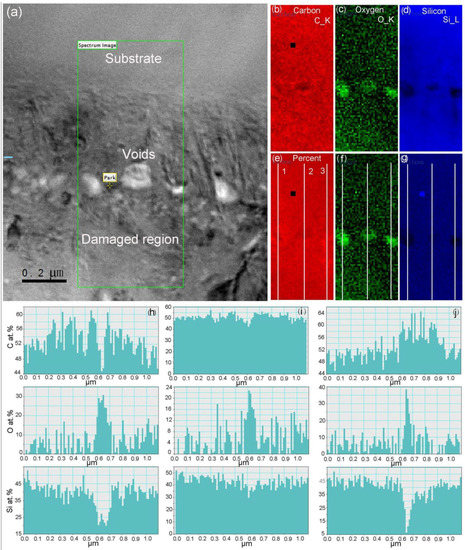
Figure 3.
Bright-field XTEM image showing (a) EELS scanning area and (b–d) C, O, and Si signal intensities, as well as (e–g) C, O, and Si atomic percentages. C, O, Si at.% from 1, 2, 3 lines illustrated in (e) are shown in (h–j), respectively.
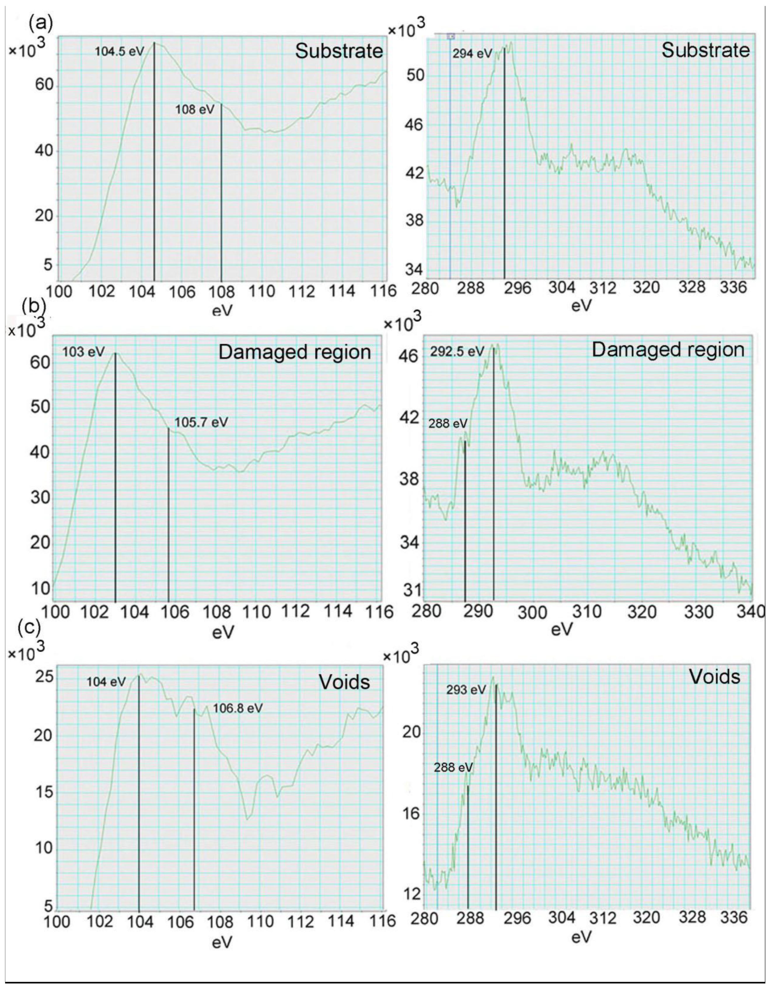
Figure 4 shows the EELS spectra of the silicon L-edge and carbon K-edge obtained at the substrate, the damage region, and the voids, respectively. In the spectrum of the substrate, a clear peak at 104.5 eV and a shoulder at 108 eV were observed from the Si_L signal. For the C_K signal, only one peak at 294 eV was observed. In the damaged region, the Si_L peak was shifted to 103 eV and the shoulder peak to 105.7 eV. At the same time, the C_K peak was divided into two peaks, one peak at 292.5 eV and the other peak at 288 eV. At the voids, the intensities of the Si_L and C_K decreased significantly due to the thinner sample in this region. The Si_L peak at 104 eV and the shoulder peak that became evident at 106.8 eV were observed. Moreover, the C_K peak at 293 eV and the shoulder peak at 288 eV were also visible.
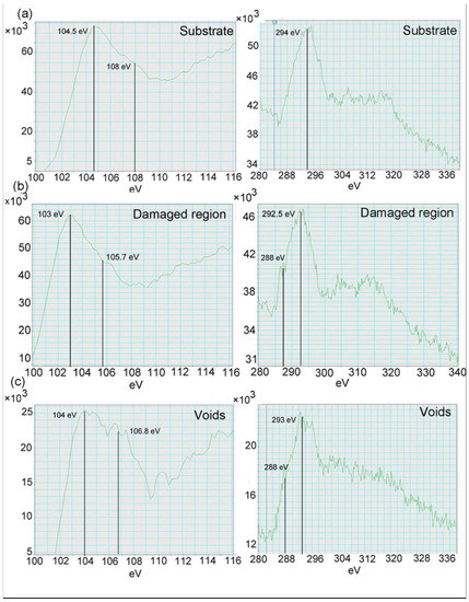
Figure 4.
The EELS spectrums recorded at (a) the substrate, (b) damaged region, and (c) the projected positions of voids.
The Si-C covalent bond is the primary component of the TEM lamellar, so the main peak should stem from the Si-C covalent bond. In addition, the TEM lamellar oxidized to form the shoulder peak in the Si_L spectrum, similar to the report of Deslandes et al. [52] who found surface oxidation during He and H co-implantation into SiC. Figure 4 shows that the profile of intensity vs. energy loss changed at different zones. This difference suggests that the electronic structure of the crystalline SiC was destroyed by lattice defects, and more electronegative bonding environment was formed in the damaged region. We can see ΔE = −1.5 eV of the main peak between the substrate and the damaged region. It should discuss the reason for the redshift of the main peak after ion irradiation. Moto et al. [29] investigated oxygen-related defect complex in SiC and found the O_K edge in the SiC sample shifted to the lower energy size by approximately 2 eV, as compared to that of SiO2. The ionization energies demonstrated the interstitial oxygen model shifted to much lower energy than that of the substitutional oxygen model. The energy loss is related to the binding energy of bonds. In general, with a stronger bond, a larger value of the energy loss is regarded. Therefore, the red-shift of the main peak is caused by the breakdown of Si-C bonds via lattice disorder, such as the increase in bond length that induces lattice swelling and change of bond angle, which can affect the intrinsic features. For example, it has been reported the increase in hydrothermal corrosion and oxidation in the damaged SiC [10,45,46,47]. There are three main reasons. One of the reasons is that the breakdown of the Si-C bonds caused the preferential reaction between silicon and oxygen. The degree of weakness of the Si-C bonds affects the oxidation rate. At the voids, the inner surface of voids contains dense silicon dangling bonds, which easily trap ambient oxygen to form Si-O bonds (an obvious shoulder peak at 106.8 eV in Figure 4c). Moreover, Figure 3 shows the rapid increase in oxygen concentration to 25 at.%. Note that the chemical shift is only 0.5 eV at voids compared to 1.5 eV in the damaged region. There are two possible reasons. One is the damage recovery at voids, because the voids are faceted with tens of nanometers that can accelerate lattice defect recovery. For example, Qin et al. [53] reported nanochannel structures in W that can enhance radiation tolerance. Wang et al. also [54] found that pre-existing nanovoids can enhance the radiation tolerance of YSZ/Al2O3 multilayered nanofilms. Pre-existing voids provide a defect “loading-unloading” effect on the inner surface of voids, resulting in the defect recovery in a short time. The other reason for the low chemical shift observed at voids is the influence of oxygen. The voids contain lots of oxygen, which reacts with Si-C bonds to form SiCOx (x < 1) complexes. Si-C, Si-C-O, Si-O, and C-C bonds were formed in the voids. This finding explains that the Si_L edge broadened significantly, as shown in Figure 4c. The sp3 bonds (Si-C bonds) can transit to sp2 (C-C) bonds in the implantation-induced amorphous SiC [29]. The peaks of sp2 bonding and sp3 bonding are located at 284 eV and 290 keV, respectively. In the present experimental results, a shoulder peak at 288 eV was formed, which indicates the weakness of Si-C bonds due to the lattice disorder, consistent with the chemical shift of Si_L edge.
4. Conclusions
In the present study, the element distribution and the chemical disorder in the He and Fe co-irradiated 6H-SiC at RT followed by the annealing at 1500 °C have been investigated. The present experimental results show that facetted voids and columnar grains with lots of stacking faults were formed in the recrystallization layer. C and O enriched, in particular at the vicinity voids, while Si diminished in the damaged region. Si-C bonds are the primary component and the energy loss of Si, C edges decreased to 1.5 eV in the damaged layer compared to those in the non-irradiated layer. It can be attributed to lattice defects that cause the breakdown of Si-C bonds. Therefore, the oxidation rate of SiC was accelerated by structural damage. Due to the high spatial resolution under the image by using a nearly parallel electron beam, EELS can detect the chemical shift of different lattice defects. It will give valuable insights into the interaction between lattice defects and corrosion species, as well as the possible role of chemical bonds in material properties.
Author Contributions
Conceptualization, G.Y.; methodology, S.W., H.Z., W.L.; formal analysis, X.G., S.R.; supervision, B.L. All authors have read and agreed to the published version of the manuscript.
Funding
The work was supported by Innovation Center of Nuclear Materials for National Defense Industry (Grant Nos. 2021-HCL-II-KYHZ-FWCG-11) and the National Natural Science Foundation of China (Grant No. 11475229).
Institutional Review Board Statement
Not applicable.
Informed Consent Statement
Not applicable.
Data Availability Statement
The data presented in this study are available on request from the corresponding authors.
Acknowledgments
We appreciated the staff of 320 kV high-voltage platform for assistance in ion irradiation.
Conflicts of Interest
The authors declare that they have no conflict of interest.
References
- Choyke, W.J.; Pernsl, G. Physical properties of SiC. Mater. Res. Soc. Bull. 1997, 22, 25. [Google Scholar] [CrossRef]
- Park, C.H.; Cheong, B.H.; Lee, K.H.; Chang, K.J. Structural and electronic properties of cubic, 2H, 4H, and 6H SiC. Phys. Rev. B 1994, 49, 4485. [Google Scholar] [CrossRef] [PubMed]
- Li, B.S.; Zhang, C.H.; Zhang, H.H.; Shibayama, T.; Yang, Y.T. Study of the damage produced in 6H-SiC by He irradiation. Vacuum 2011, 86, 452. [Google Scholar] [CrossRef]
- Wang, Y.; Liao, Q.; Liu, M.; Zhang, P.F.; Gao, X.Y.; Jia, Z.; Xu, S.; Li, B.S. Optical spectroscopy study of damage evolution in 6H-SiC by H2+ implantation. Chin. Phys. B 2021, 30, 056106. [Google Scholar] [CrossRef]
- Li, B.S.; Wang, Z.G. Structures and optical properties of H2+-implanted GaN epi-layers. J. Phys. D Appl. Phys. 2015, 48, 225101. [Google Scholar] [CrossRef] [Green Version]
- Du, Y.Y.; Li, B.S.; Wang, Z.G.; Sun, J.R.; Yao, C.F.; Chang, H.L.; Pang, L.L.; Zhu, Y.B.; Cui, M.H.; Zhang, H.P.; et al. Spectra study of He-irradiation induced defects in 6H-SiC. Acta Phys. Sin. 2014, 63, 216101. [Google Scholar]
- Li, J.J.; Hang, H.F.; Huang, Q.; Tang, M.; Zhao, B.; Ji, G.W.; Zhang, W.; Xie, R.B.; Yan, L. Effect of irradiation damage on corrosion of 4H-SiC in FLiNaK molten salt. Corros. Sci. 2017, 125, 194. [Google Scholar] [CrossRef]
- Li, J.J.; Yan, L.; Huang, H.F.; Huang, Q.; Ren, C.L.; Lei, G.H.; Lin, J.; Fu, C.L.; Bai, J.J. Corrosion behavior of ion-irradiated SiC in FLiNaK molten salt. Corros. Sci. 2020, 163, 108229. [Google Scholar] [CrossRef]
- Li, B.S.; Sheng, Y.B.; Liu, H.P.; Lu, X.R.; Shu, X.Y.; Xiong, A.L.; Wang, X. Dissolution corrosion of 4H-SiC in lead-bismuth eutectic at 550 °C. Mater. Corros. 2019, 70, 1878. [Google Scholar] [CrossRef]
- Doyle, P.; Sun, K.C.; Snead, L.; Katoh, Y.; Bartels, D.; Zinkle, S.; Raiman, S. The effects of neutron and ionizing irradiation on the aqueous corrosion of SiC. J. Nucl. Mater. 2020, 536, 152190. [Google Scholar] [CrossRef]
- Makhtari, A.; Raineri, V.; Via, F.L.; Franzo, G.; Frisina, F.; Calcagno, L. Structural characterization of titanium silicon carbide reaction. Mater. Sci. Semi. Proc. 2001, 4, 345. [Google Scholar] [CrossRef]
- Kondo, S.; Lee, M.; Hinoki, T.; Hyodo, Y.; Kano, F. Effect of irradiation damage on hydrothermal corrosion of SiC. J. Nucl. Mater. 2015, 464, 36. [Google Scholar] [CrossRef]
- Xi, J.Q.; Liu, C.; Szlufarska, I. Effects of point defects on oxidation of 3C-SiC. J. Nucl. Mater. 2020, 538, 152308. [Google Scholar] [CrossRef]
- Zhang, L.F.; Diallo, L.; Fnidiki, A.; Lechevallier, L.; Declemy, A.; Lefebvre, W.; Juraszek, J. Probing the origins of magnetism in 2 at% Fe-implanted 4H-SiC. Scr. Mater. 2020, 188, 157. [Google Scholar] [CrossRef]
- Declemy, A.; Drouet, M.; Eymery, J.P.; Dupeyrat, C.; Ott, F.; Viret, M. Microstructural study of ferromagnetic Fe-implanted 6H-SiC. Phys. Stat. Sol. 2007, 4, 1473. [Google Scholar] [CrossRef]
- Li, B.S.; Peng, D.P.; Li, J.H.; Kang, L.; Zhang, T.M.; Zhang, Z.X.; Jin, S.X.; Cao, X.Z.; Liu, J.H.; Wu, L.; et al. Magnetic and structural properties of Fe-implanted GaN at room temperature. Vacuum 2021, 184, 109909. [Google Scholar] [CrossRef]
- Leung, J.W.; Ascheron, C.E.; Petravic, M.; Elliman, R.G.; Williams, J.S. Getting of copper to hydrogen-induced cavities in silicon. Appl. Phys. Lett. 1995, 66, 1231. [Google Scholar] [CrossRef]
- Brett, D.A.; Llewellyn, D.J.; Ridgway, M.C. Trapping of Pd, Au, and Cu by implantation-induced nanocavities and dislocations in Si. Appl. Phys. Lett. 2006, 88, 222107. [Google Scholar] [CrossRef]
- Oliviero, E.; Beafort, M.F.; Barbot, J.F.; Veen, A.V.; Fedorov, A.V. Helium implantation defects in SiC stuies by thermal helium desorption spectrometry. J. Appl. Phys. 2003, 93, 231. [Google Scholar] [CrossRef]
- Sourieul, S.; Costantini, J.M.; Gosmain, L.; L Thome, L.; Grob, J.J. Raman spectroscopy study of heavy-ion-irradiated α-SiC. J. Phys. D Condens. Matter 2006, 18, 5235. [Google Scholar] [CrossRef]
- Wang, P.F.; Huang, L.; Zhu, W.; Ruan, Y.F. Raman scattering of neutron irradiated 6H-SiC. Solid State Commun. 2012, 152, 887. [Google Scholar] [CrossRef]
- Zhang, L.M.; Jiang, W.L.; Ai, W.S.; Chen, L.; Wang, T.S. Ion irradiation induced nucleation and growth of nanoparticles in amorphous silicon carbide at elevated temperatures. J. Nucl. Mater. 2018, 505, 249. [Google Scholar] [CrossRef]
- Weber, W.J.; Wang, L.M.; Yu, N. The irradiation-induced crystalline-to-amorphous phase transition in α-SiC. Nucl. Instrum. Methods B 1996, 116, 322. [Google Scholar] [CrossRef]
- Li, B.S.; Zhang, C.; Liu, H.P.; Xu, L.J.; Wang, X.; Yang, Z.; Ge, F.F.; Gao, W.; Shen, T.L. Microstructural and elemental evolution of polycrystalline α-SiC irradiated with ultra-high-fluence helium ions before and after annealing. Fusion Eng. Des. 2020, 154, 111511. [Google Scholar] [CrossRef]
- Li, B.S.; Du, Y.Y.; Wang, Z.G.; Wei, K.F.; Zhang, H.P.; Yao, C.F.; Chang, H.L. Transmission electron microscopy investigations of bubble formation in He-implanted polycrystalline SiC. Vacuum 2015, 113, 75. [Google Scholar] [CrossRef]
- Chen, K.F.; Chen, C.H.; Zeng, Z.H.; Chen, F.R.; Kai, J.J. Quantifying helium distribution in dual-ion beam irradiated SiCf/SiC composites by electron energy loss spectroscopy. Prog. Nucl. Energy 2012, 57, 46. [Google Scholar] [CrossRef]
- Muto, S.; Tanabe, T.; Shibayama, T.; Takahashi, H. Damaging process of a-SiC under electron irradiation studied with electron microscopy and spectroscopy. Nucl. Instrum. Methods B 2002, 191, 519. [Google Scholar] [CrossRef]
- Muto, S.; Tanabe, T.; Maruyama, T. Cross sectional TEM observation of Gas-ion irradiation induced surface blisters and their precursors in SiC. Mater. Trans. 2003, 44, 2599. [Google Scholar] [CrossRef] [Green Version]
- Muto, S.; Sugimaya, H.; Kumura, T.; Tanabe, T. Structure of an Oxygen-Related Defect Complex in SiC Studied with Electron Energy-Loss Spectroscopy. Jpn. J. Appl. Phys. 2004, 43, 1076. [Google Scholar] [CrossRef]
- Jin, S.X.; Ma, H.L.; Lu, E.Y.; Zhang, Q.L.; Fan, P.; Yan, Q.Z.; Yuan, D.Q.; Cao, X.Z.; Wang, B.Y. Depth distribution of cavities in advanced ferritic/martensitic and austenitic steels with high helium preimplantation and high damage level. Mater. Today Energy 2021, 20, 100687. [Google Scholar] [CrossRef]
- Qin, W.J.; Jin, S.X.; Cao, X.Z.; Wang, Y.Q.; Peres, P.; Choi, S.Y.; Jiang, C.Z.; Ren, F. Influence of nanochannel structure on helium-vacancy cluster evolution and helium retention. J. Nucl. Mater. 2019, 527, 151822. [Google Scholar] [CrossRef]
- Currell, F.J. Springer Book Archive; Springer Nature: Belfast, UK, 2003; pp. 3–37. ISBN 978-94-017-0542-4. [Google Scholar]
- Devanathan, R.; Weber, W.J. Displacement energy surface in 3C and 6H SiC. J. Nucl. Mater. 2000, 278, 258. [Google Scholar] [CrossRef]
- Daghbouj, N.; Li, B.S.; Callisti, M.; Sen, H.S.; Karlik, M.; Polcar, T. Microstructural evolution of helium -irradiated 6H-SiC subjected to different irradiation conditions and annealing temperature A multiple characterization study. Acta Mater. 2019, 181, 160. [Google Scholar] [CrossRef]
- Daghbouj, N.; Li, B.S.; Callisti, M.; Sen, H.S.; Lin, J.; Ou, X.; Karlik, M.; Polar, T. The structural evolution of light-ion implanted 6H-SiC single crystal_ Comparison of the effect of helium and hydrogen. Acta Mater. 2020, 188, 609. [Google Scholar] [CrossRef]
- Han, Z.; Wang, X.; Wang, J.; Liao, Q.; Li, B.S. Formation of nano-twinned 3C-SiC grains in Fe-implanted 6H-SiC after 1500-°C annealing. Chin. Phys. B 2021, 30, 086107. [Google Scholar] [CrossRef]
- Eaglesham, D.J.; White, A.E.; Feldman, L.C.; Moriya, N.; Jacobson, D.C. Equilibrium shape of Si. Phys. Rev. Lett. 1993, 70, 1643. [Google Scholar] [CrossRef]
- Kondo, S.; Parish, C.M.; Koyanagi, T.; Katoh, Y. Equilibrium shapes and surface selection of nanostructures in 6H-SiC. Appl. Phys. Lett. 2017, 110, 142106. [Google Scholar] [CrossRef] [Green Version]
- Xi, J.Q.; Liu, B.; Yuan, F.L.; Zhang, Y.W.; Weber, W.J. Diffusion of point defects near stacking faults in 3C-SiC via first-principles calculations. Scr. Mater. 2017, 139, 1. [Google Scholar] [CrossRef]
- Li, B.S.; Yang, Z.; Xu, S.; Wei, K.F.; Wang, Z.G.; Shen, T.L.; Zhang, T.M.; Liao, Q. Comparison of helium bubble formation in F82H, ODS, SIMP and T91 steels irradiated by Fe and He ions simultaneously. Chin. Phys. B 2021, 30, 036102. [Google Scholar] [CrossRef]
- Yang, Z.; Yang, J.Y.; Liao, Q.; Xu, S.; Li, B.S. Effect of helium concentration on irradiation damage of Fe-ion irradiated SIMP steel at 300 °C and 450 °C. Chin. Phys. B 2021, 30, 056107. [Google Scholar] [CrossRef]
- Krsjak, V.; Degmova, J.; Sojak, S.; Slugen, V. Effects of displacement damage and helium production rates on the nucleation and growth of helium bubbles-Positron annihilation spectroscopy aspects. J. Nucl. Mater. 2018, 499, 38. [Google Scholar] [CrossRef]
- Li, B.S.; Wang, Z.G.; Wei, K.F.; Shen, T.L.; Yao, C.F.; Zhang, H.P.; Sheng, Y.B.; Lu, X.R.; Xiong, A.L.; Han, W.T. Evaluation of helium effect on irradiation hardening in F82H, ODS, SIMP and T91 steels by nano-indentation method. Fusion Eng. Des. 2019, 142, 6. [Google Scholar] [CrossRef]
- Sun, J.J.; You, Y.W.; Wu, X.B.; Song, H.Y.; Li, B.S.; Liu, C.X.; Krsjak, V. Segregation and diffusion behavior of helium at grain boundaries in silicon carbide ceramics: First-principles calculations and experimental investigation. J. Eur. Ceram. Soc. 2022, 42, 4066. [Google Scholar] [CrossRef]
- Steinbrueck, M.; Avincola, V.A.; Markel, I.J.; Stegmaier, U.; Gerhards, U.; Seifert, H.J. Oxidation of SiCf-SiC CMC cladding tubes for GFR application in impure helium atmosphere and materials interactions with tantalum liner at high temperature up to 1600 °C. J. Nucl. Mater. 2019, 517, 337. [Google Scholar] [CrossRef]
- Costello, J.A.; Tressler, R.E. Oxidation kinetic of hot-pressed and sinerted α-SiC. J. Am. Ceram. Soc. 1981, 64, 327. [Google Scholar] [CrossRef]
- Makhtari, A.; Raineri, V.; Calcagno, L.; Lavia, F.; Frisina, F.; Foti, G. Enhanced oxidation of ion-damaged 6H-SiC. Philos. Mag. 2000, 4, 661. [Google Scholar] [CrossRef]
- Kondo, S.; Hinoki, T.; Nonaka, M.; Ozawa, K. Irradiation-induced shrinkage of highly crystalline SiC fibers. Acta Mater. 2015, 83, 1. [Google Scholar] [CrossRef]
- Barcz, A.; Kozubal, M.; Jakiela, R.; Ratajczak, J.; Dyczewski, J.; Colaszewska, K.; Wojciechowski, T.; Celler, G.K. Diffusion and impurity segregation in hydrogen-implanted silicon carbide. J. Appl. Phys. 2014, 115, 223710. [Google Scholar] [CrossRef]
- Was, G.S.; Taller, S.; Jiao, Z.; Monterrosa, A.M.; Woodley, D.D.; Jennings, D.; Kubley, T.; Naab, F.; Toader, O.; Uberseder, E. Resolution of the carbon contamination problem in ion irradiation experiments. Nucl. Instrum. Methods B 2017, 412, 58. [Google Scholar] [CrossRef]
- Li, J.; Eveno, P.; Huntz, A.M. Oxidation of SiC. Werkst. Korros. 1990, 41, 716. [Google Scholar] [CrossRef]
- Deslandes, A.; Guenette, M.C.; Thomsen, L.; Ionescu, M.; Karatchevtseva, I.; Lumpkin, G.R. Retention and damage in 3C-β SiC irradiated with He and H ions. J. Nucl. Mater. 2016, 469, 187. [Google Scholar] [CrossRef]
- Qin, W.J.; Ren, F.; Doerner, R.P.; Wei, G.; Lv, Y.W.; Chang, S.; Tang, M.; Deng, H.Q.; Jiang, C.Z.; Wang, Y.Q. Nanochannel structures in W enhance radiation tolerance. Acta Mater. 2018, 153, 147. [Google Scholar] [CrossRef]
- Wang, H.; Fen, F.; Tang, J.; Qin, W.J.; Hu, L.L.; Dong, L.; Yang, B.; Cai, G.X.; Jiang, C.Z. Enhanced radiation tolerance of YSZ/Al2O3 multilayered nanofilms with pre-existing nanovoids. Acta Mater. 2018, 144, 691. [Google Scholar] [CrossRef]
Publisher’s Note: MDPI stays neutral with regard to jurisdictional claims in published maps and institutional affiliations. |
© 2022 by the authors. Licensee MDPI, Basel, Switzerland. This article is an open access article distributed under the terms and conditions of the Creative Commons Attribution (CC BY) license (https://creativecommons.org/licenses/by/4.0/).

