
Intermetallic Compounds Formation during 316L Stainless Steel Reaction with Al-Zn-Si Coating Alloy

 ,
,  , , and
Abstract
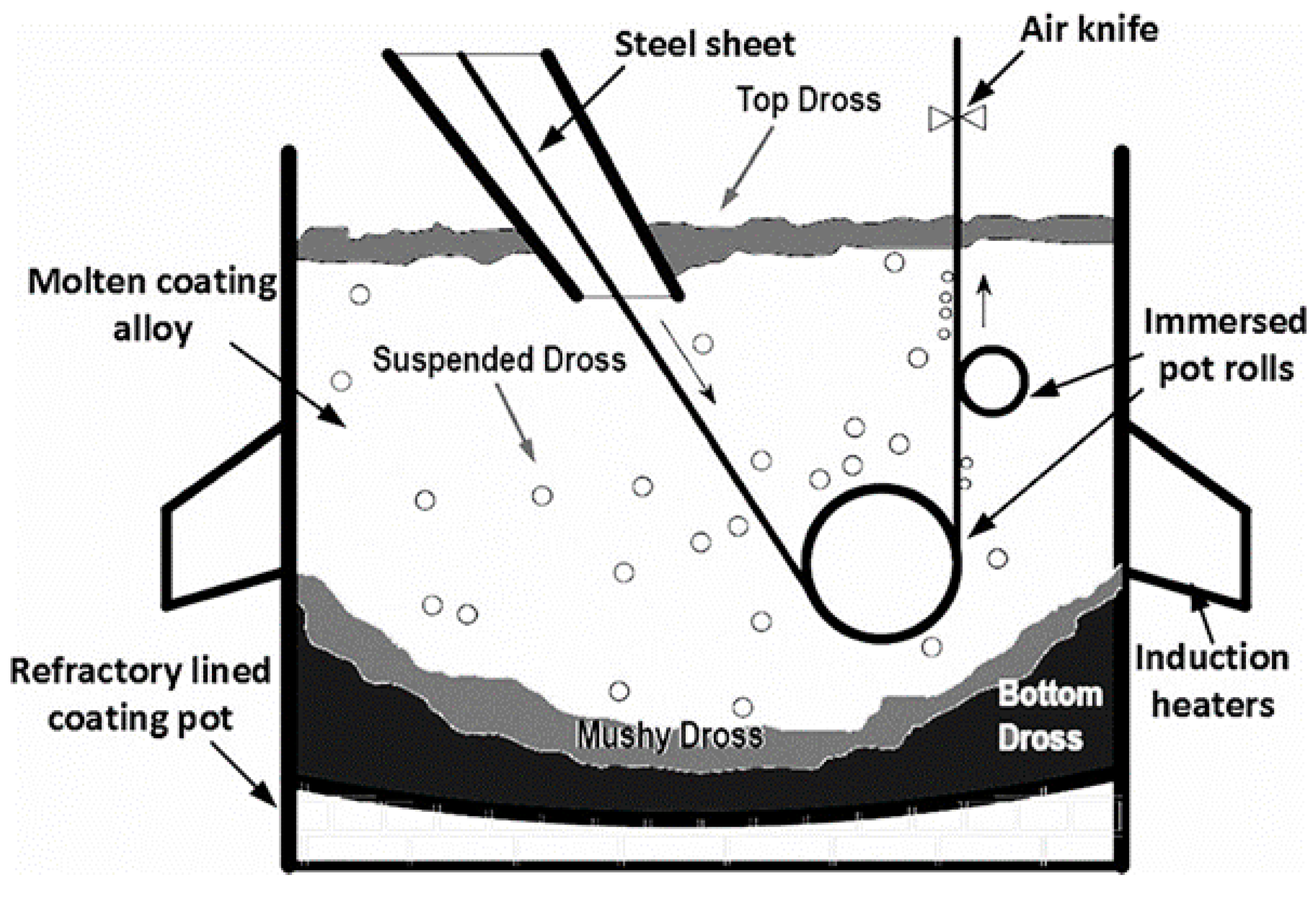
:1. Introduction
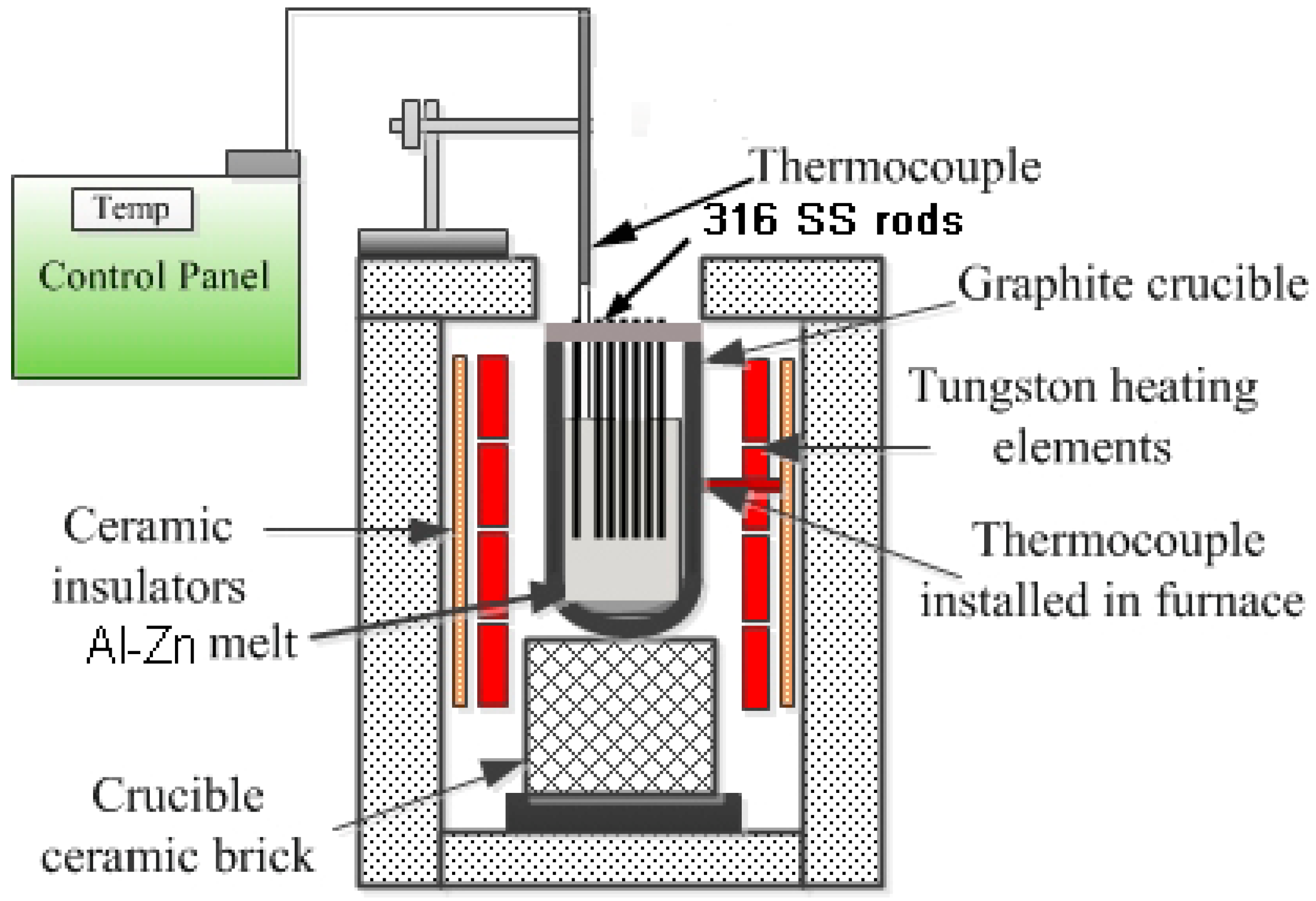
2. Materials and Methods
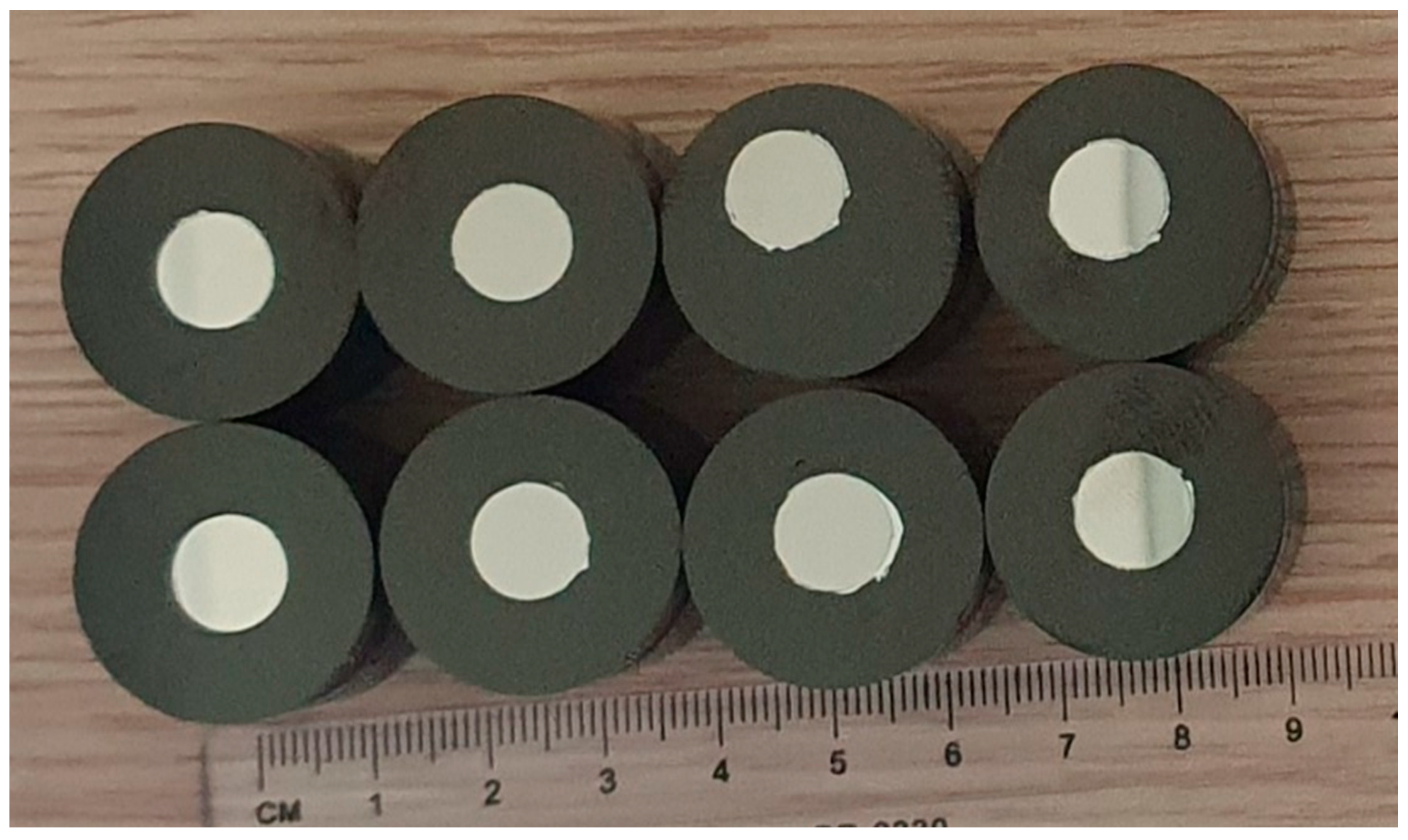
2.1. Experimental Plan
2.2. Characterization Techniques
3. Thermodynamic Assessment of Al, Fe, Si, Cr, V and Si System
3.1. Thermodynamic Modeling
- The reactions are conducted at ambient condition (one atmospheric pressure) but at different temperatures, which implies that the gaseous species composition has no influence.
- Unit activity of the elements is considered in the standard state, and all the atoms/molecules interact freely to attain the lowest energy state.
- The calculations are conducted at equilibrium, assuming that the lowest energy state is obtained independent of the reaction kinetics.
- The reactions are conducted in a closed system.
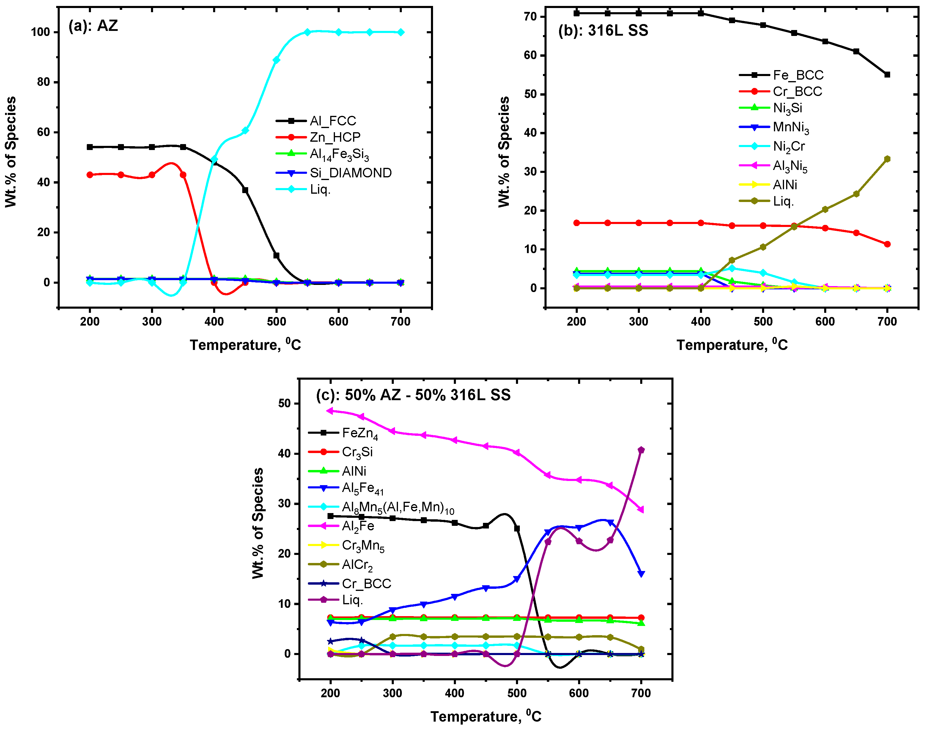
3.2. Equilibrium Products
4. Results and Discussion
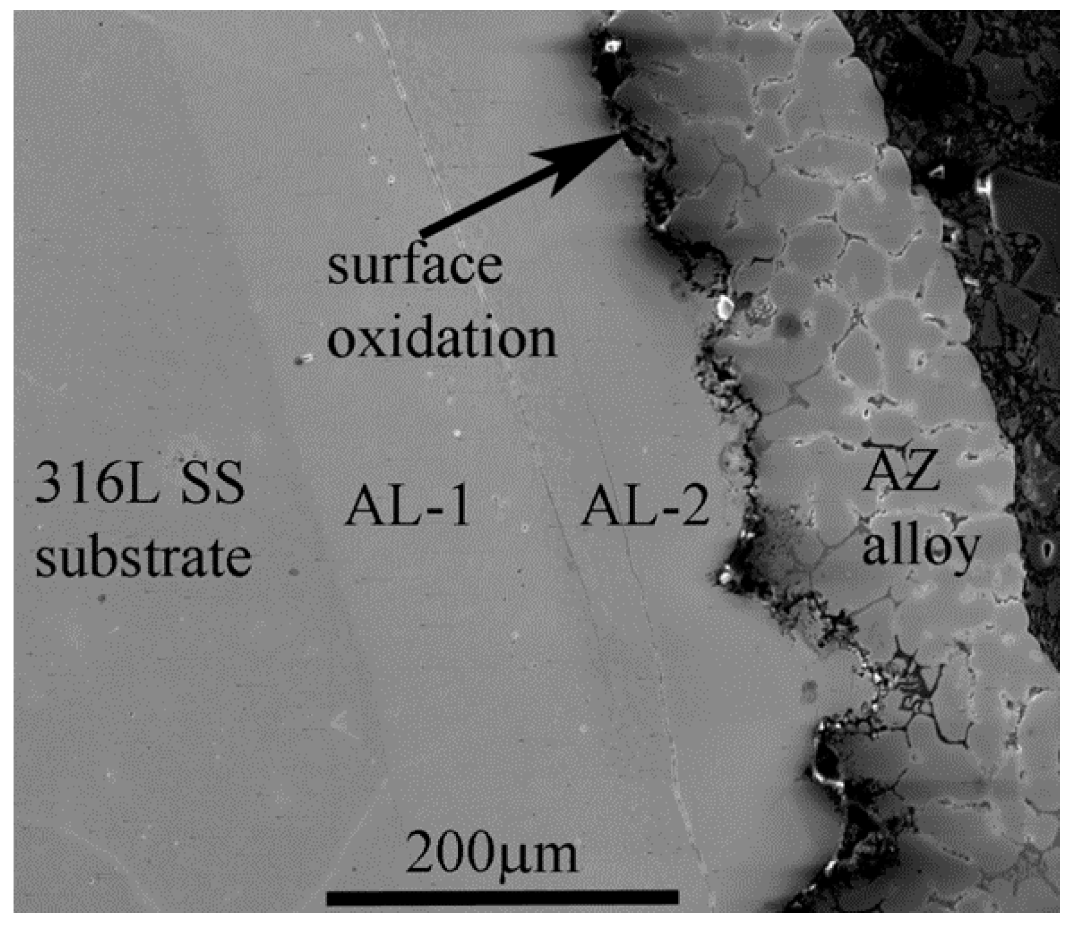
4.1. Microstructural Analysis of the Interface
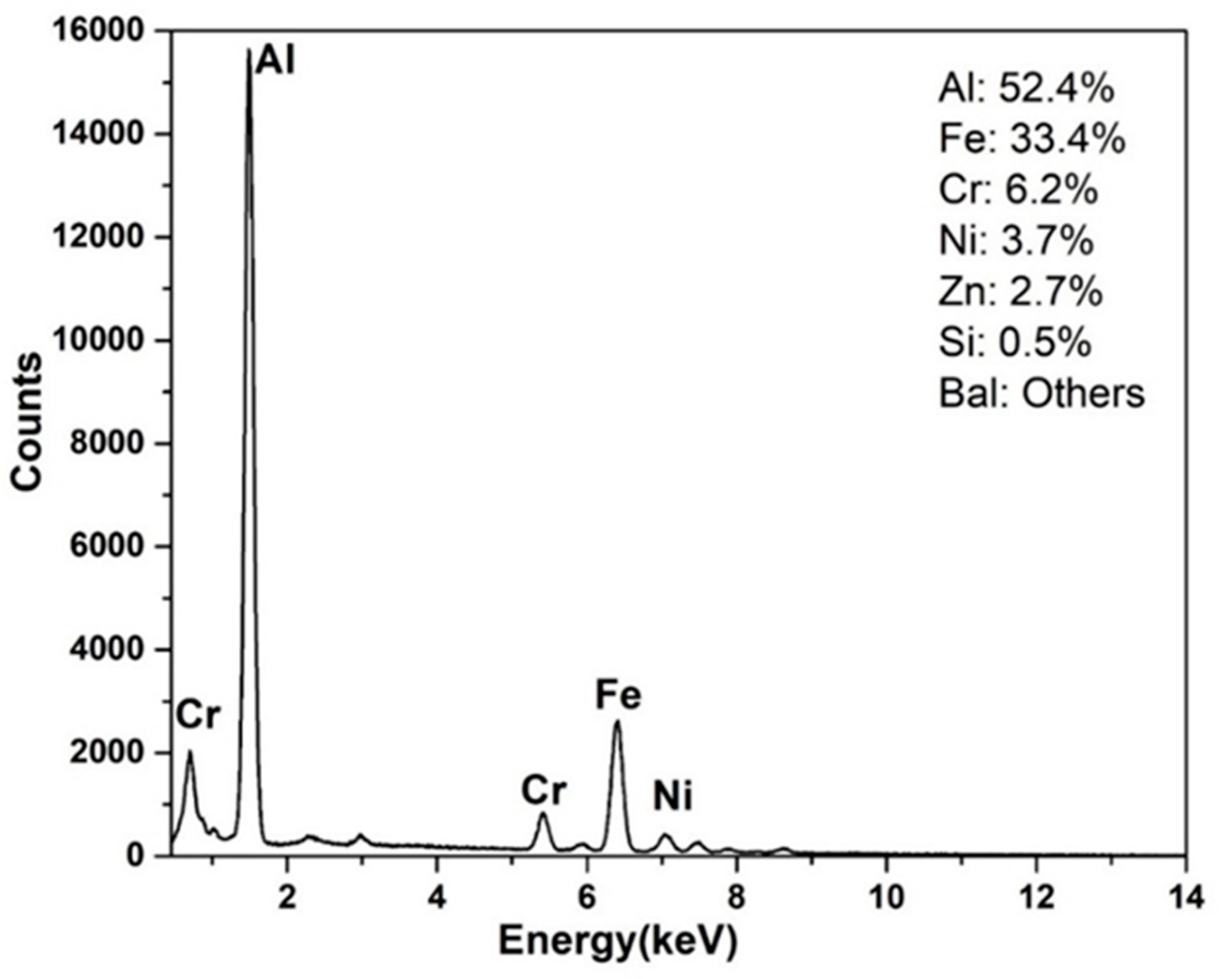
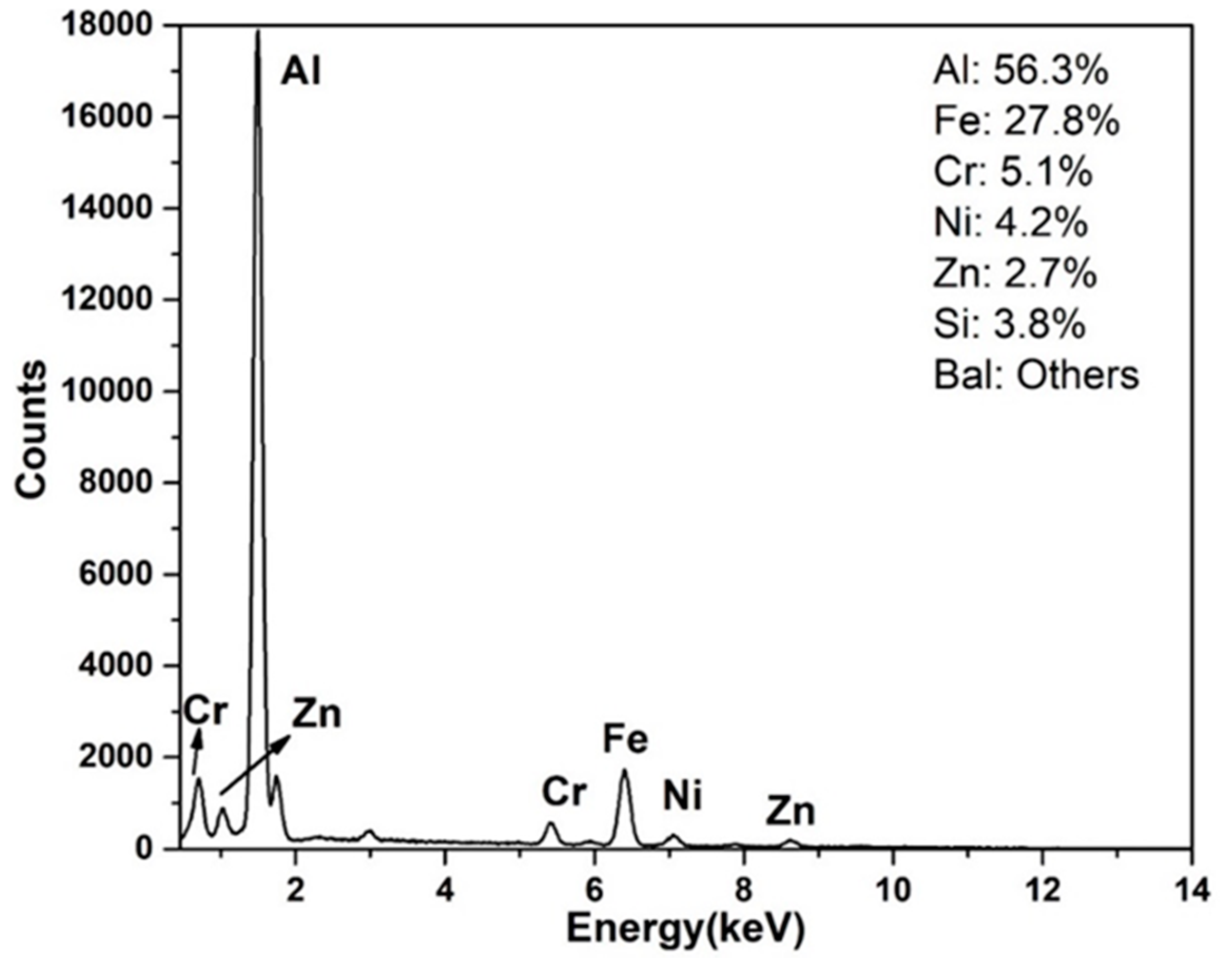
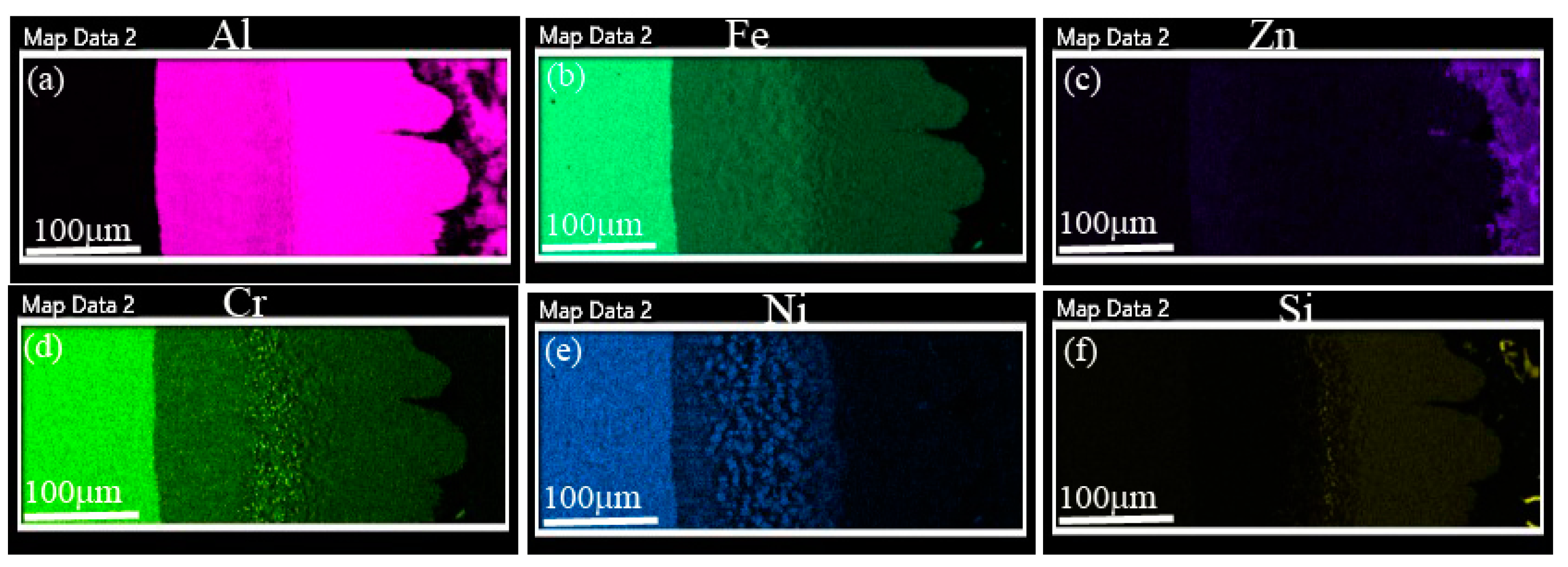
4.2. Compositional Analysis of the IMC Layers
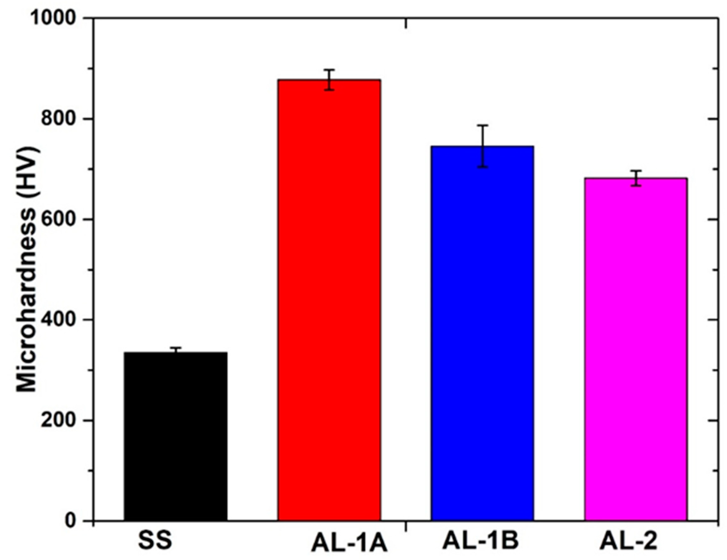
5. Microhardness Analysis of SS, AL-1 and AL-2
6. IMC Layers Formation Mechanism
7. Conclusions
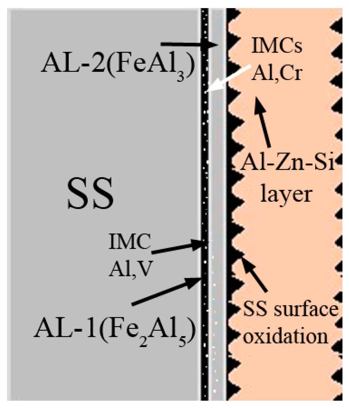
- The 316L SS reacts with the Al-Zn-Si coating alloy at 600 °C. As a result, two distinct IMC layers are developed between the SS substrate and AZ coating alloy.
- Iron diffusion from the SS substrate into AZ melt and Al mass transfer into a solid SS substrate are inevitable. The chemical reaction between Al and Fe is rapid, which forms Fe-based IMC layer at the interface.
- The interfacial layer is composed of two distinct intermetallic compounds (IMCs). The layer adjacent to the SS substrate is Fe2Al5 (AL-1) and that formed adjacent to the AZ coating alloy is FeAl3 (AL-2). The EDS analysis confirms nature of the IMC layers. These findings are in agreement with the previous works.
- Cr and Ni diffused out from the SS substrate to form discrete Al7Cr/Al4Cr and AlNi IMC particles. It is suggested that such IMC particles precipitate during the solidification process, once Cr and Ni solubility have decreased with temperature.
- The FactSage thermodynamic analysis also predicted the formation of AlCr and AlNi IMC particles, in addition to Fe2Al5 and FeAl3.
- The 316L SS surface hardness increased significantly during immersion in the AZ coating alloy at 600 °C. The AL-1 and AL-2 hardness was 877 HV and 681 HV, respectively.
- A longitudinal crack developed between the AL-1 and AL-2 IMC layers, which is one of the key findings of this study.
Author Contributions
Funding
Institutional Review Board Statement
Informed Consent Statement
Data Availability Statement
Acknowledgments
Conflicts of Interest
References
- Marder, A.R. The Metallurgy of zinc-coated steel. Prog. Mater. Sci. 2000, 45, 191–271. [Google Scholar] [CrossRef]
- Setargew, N.; Hodges, J.; Parker, D. Dross Intermetallic Formation and the Alloy Layer in 55%Al-Zn Coating Systems; Steel Research Hub, University of Wollongong: Wollongong, Australia, 2015; pp. 1–30. [Google Scholar]
- Borzillo, A.R.; Horton, J.B. Ferrous Metal Article Coated with an Aluminum Zinc Alloy. U.S. Patent 3,343,930, 26 September 1967. [Google Scholar]
- Borzillo, A.R.; Horton, J.B. Method of Forming Improved Zinc-Aluminum Coating on Ferrous Surfaces. U.S. Patent 3,393,089, 16 July 1968. [Google Scholar]
- Khaliq, A.; Parker, D.J.; Setargew, N.; Kondoh, K.; Qian, M. Dissolution Kinetics of Iron-Based Intermetallic Compounds (τ5c IMCs) in a Commercial Steel Strip Metallic Alloy Coating Process. Metall. Mater. Trans. B 2021, 52, 41–50. [Google Scholar] [CrossRef]
- Willis, D.J.; Setargew, N. Bottom Dross Formation Mechanisms in Zincalume Coating Line Pots; InterZAC: Seoul, Korea, 2002; pp. 1–17. [Google Scholar]
- Williams, J.; Smith, R.; Neufeld, A.K. An Investigative Study of Phase and Structure Formation in AM Coatings, Corrosion & Prevention; Australasian Corrosion Association (ACA): Brisbane, Australia, 2013. [Google Scholar]
- Khaliq, A.; Parker, D.J.; Setargew, N.; Qian, M. Fabrication of the τ5c Intermetallic Compound Monoliths by a Novel Powder Metallurgy and Hot-Dipping Approach. Metall. Mater. Trans. B 2020, 51, 836–849. [Google Scholar] [CrossRef]
- Chen, R.Y.; Yuen, D. Microstructure and crystallography of Zn-55Al-1.6Si coating spangle on steel. Metall. Mater. Trans. A Phys. Metall. Mater. Sci. 2012, 43, 4711–4723. [Google Scholar] [CrossRef]
- Setargew, N.; Willis, D.J.; Thompson, D. Detection of Dross Intermetallic Particles in 55%Al-Zn Melt Using LAIS; InterZAC: Seoul, Korea, 2004; pp. 1–16. [Google Scholar]
- Tang, N. Dross Management in Continous Galvanizing; Cominco Ltd.: Mississauga, ON, Canada, 1999. [Google Scholar]
- Liu, X.; Barbero, E.; Xu, J.; Burris, M.; Chang, K.M.; Sikka, V. Liquid metal corrosion of 316L, Fe3Al, and FeCrSi in molten Zn-Al baths. Metall. Mater. Trans. A 2005, 36, 2049–2058. [Google Scholar] [CrossRef]
- Khaliq, A.; Subhani, T.; Ali, H. Analysis of 316L Stainless Steel Interaction with Galvanizing Alloy Bath. Microsc. Microanal. 2020, 26 (Suppl. 2), 2884–2886. [Google Scholar] [CrossRef]
- Dybkov, V.I. Interaction of 18Cr-10Ni stainless steel with liquid aluminum. J. Mater. Sci. 1990, 25, 3615–3633. [Google Scholar] [CrossRef]
- Loto, R.T.; Özcan, E. Corrosion Resistance Studies of Austenitic Stainless Steel Grades in Molten Zinc-Aluminum Alloy Galvanizing Bath. J. Fail. Anal. Prev. 2016, 16, 427–437. [Google Scholar] [CrossRef] [Green Version]
- Zhang, K.; Battiston, L. Sliding wear of various materials in molten zinc Sliding wear of various materials in molten zinc. Mater. Sci. Technol. 2002, 18, 1551–1560. [Google Scholar] [CrossRef]
- Yuan, B.; Liao, D.; Jiang, W.; Deng, H.; Li, G. Investigation on corrosion mechanism of stirring paddles of different iron-based materials in ZL101 aluminum melt. J. Mater. Res. Technol. 2021, 13, 1992–2005. [Google Scholar] [CrossRef]
- Xu, J.; Bright, M.A.; Liu, X.; Barbero, E. Liquid Metal Corrosion of 316L Stainless Steel, 410 Stainless Steel, and 1015 Carbon Steel in a Molten Zinc Bath. Metall. Mater. Trans. A 2007, 38, 2727–2736. [Google Scholar] [CrossRef]
- Zhang, K.; Tang, N.Y.; Goodwin, F.E.; Sexton, S. Goodwin, Scott Sexton, Reaction of 316L stainless steel with a galvanizing bath. J. Mater. Sci. 2007, 42, 9736–9745. [Google Scholar] [CrossRef]
- Available online: www.factsage.com (accessed on 10 March 2022).
- Bale, C.W.; Chartrand, P.; Decterov, S.A.; Eriksson, G.; Hack, K.; Mahfoud, R.B.; Melançon, J.; Pelton, A.D.; Petersen, S. FactSage Thermochemical Software and Databases. Calphad J. 2002, 62, 189–228. [Google Scholar] [CrossRef]
- Bellini, C.; Carlino, F. Intermetallic phase kinetic formation and thermal crack development in galvanized DCI. Frat. Integrita Strutt. 2019, 48, 740–747. [Google Scholar] [CrossRef]
- Khaliq, A.; Ali, H.T.; Yusuf, M. Thermodynamic and kinetic analysis of CrB2 and VB2 formation in molten Al–Cr–V–B alloy. Trans. Nonferrous Met. Soc. China 2021, 31, 3162–3176. [Google Scholar] [CrossRef]
- Rajhi, W.; Ayadi, B.; Khaliq, A.; Al-Ghamdi, A.; Ramadan, M.; Al-shammrei, S.; Boulila, A.; Aichouni, M. Constitutive behavior and fracture of intermetallic compound layer in bimetallic composite materials: Modeling and application to bimetal forming process. Mater. Des. 2021, 212, 110294. [Google Scholar] [CrossRef]
- Kobayashi, S.; Yakou, T. Control of intermetallic compound layers at interface between steel and aluminum by diffusion-treatment. Mater. Sci. Eng. A 2002, 338, 44–53. [Google Scholar] [CrossRef]


| Elements | Fe | Cr | Ni | Mn | Si | Al | Zn | Minor |
|---|---|---|---|---|---|---|---|---|
| 316L SS | 70.9 | 17.9 | 9.4 | 0.9 | 0.6 | 0.1 | - | Balance |
| AZ alloy | 0.4 | - | - | - | 1.6 | 55 | 43 | Balance |
| Gas | Liquid | Solid | Solid | Solid | |
|---|---|---|---|---|---|
| Zn | Zn | Zn_BCT | Mn_HCP | Al12(Fe,Mn) | Al3Fe |
| Mn | Cr | Zn_DIAMOND | Al_BCC | AlNi | AL8MN5D810/(Al,Si)12Mn4(Al,Fe,Mn)10 |
| Al | Al | Cr_BCC | Al_HCP | Al3Ni2 | Al13Fe4 (FeAl3) |
| Cr | Solid | Cr_HCP | Al_CBCC | Al5Fe4 | Al4Mn |
| Fe | Fe_BCC | Cr_CUB | Al_CUB | Al2Fe | FeSi |
| Ni | Fe_FCC | Cr_CBCC | Al8Cr5 | Al5Fe41 | (Fe, Mn)3Si |
| Al2 | Fe_HCP | Ni_HCP | FeZn4 | Al5Fe2 | Fe5Si3 |
| Si | Fe_ORTHORHO | Ni_BCC | Al4Mn | Al5Fe21 | Al6Mn |
| Si2 | Fe_TETRAGON | Ni_CUB | Cr3Si | NiZn8 | Al11Mn41 |
| Si3 | Zn_HCP | Ni_FCC | Al11Cr2 | Ni2Si | |
| Zn_BCC | Mn_FCC | Ni5Si2 | CrZn13 |
Publisher’s Note: MDPI stays neutral with regard to jurisdictional claims in published maps and institutional affiliations. |
© 2022 by the authors. Licensee MDPI, Basel, Switzerland. This article is an open access article distributed under the terms and conditions of the Creative Commons Attribution (CC BY) license (https://creativecommons.org/licenses/by/4.0/).
Share and Cite
Khaliq, A.; Alghamdi, A.S.; Ramadan, M.; Subhani, T.; Rajhi, W.; Haider, W.; Hasan, M.M. Intermetallic Compounds Formation during 316L Stainless Steel Reaction with Al-Zn-Si Coating Alloy. Crystals 2022, 12, 735. https://doi.org/10.3390/cryst12050735
Khaliq A, Alghamdi AS, Ramadan M, Subhani T, Rajhi W, Haider W, Hasan MM. Intermetallic Compounds Formation during 316L Stainless Steel Reaction with Al-Zn-Si Coating Alloy. Crystals. 2022; 12(5):735. https://doi.org/10.3390/cryst12050735
Chicago/Turabian StyleKhaliq, Abdul, Abdulaziz S. Alghamdi, Mohamed Ramadan, Tayyab Subhani, Wajdi Rajhi, Waseem Haider, and Mohammad Mehedi Hasan. 2022. "Intermetallic Compounds Formation during 316L Stainless Steel Reaction with Al-Zn-Si Coating Alloy" Crystals 12, no. 5: 735. https://doi.org/10.3390/cryst12050735