Article

Surface Shape Evolution of Optical Elements during Continuous Polishing of Fused Quartz

1
School of Mechatronics Engineering, Harbin Institute of Technology, Harbin 150001, China
2
State Key Laboratory of Robotics and System (HIT), Harbin Institute of Technology, Harbin 150001, China
*
Authors to whom correspondence should be addressed.
Crystals 2022, 12(5), 736; https://doi.org/10.3390/cryst12050736
Submission received: 25 April 2022 / Revised: 12 May 2022 / Accepted: 17 May 2022 / Published: 20 May 2022
(This article belongs to the Special Issue Processing Technology of Brittle Crystal Materials)

Abstract

:
Continuous polishing is the first choice for machining optical elements with a large aperture. The lubrication in the continuous polishing is an important factor affecting the surface quality of the optical elements. In this study, the lubrication system between the optic element and polishing lap was analyzed firstly and then was verified by the measurement experiment of the friction coefficient. In addition, the numerical simulation model of the mixture lubrication was established. The polishing pressure distribution and material removal distribution can be obtained by the model. The influences of the rotating speed, optical element load, and surface roughness of the polishing lap on polishing pressure were also analyzed. Finally, the influence rules of the lubrication on the surface shape of optical elements were revealed by the polishing experiments.

1. Introduction

Abrasive machining technologies such as grinding and polishing are the necessary means to realize the precision machining of optical elements [1,2,3]. Continuous polishing technology is a full-aperture covering method for polishing optics. The research on continuous polishing is more qualitative than quantitative. The machining instability of the continuous polishing seriously restricts the efficiency of planar optical elements with a large aperture. To reduce the production cycle and processing cost, it is necessary to enhance the understanding of the continuous polishing technology and solve the key problems which restrict the development of the continuous polishing [4,5,6,7,8].
The lubrication in the continuous polishing area is an important factor affecting the surface quality of optical elements [9]. It affects the polishing pressure and material removal rate, and has a distinct influence on the surface shape of the substrates [10,11]. Therefore, the study on the lubrication of the machining area is of great significance to reveal the removal mechanism of the continuous polishing technology [12,13].
Chang et al. [14] studied the thickness of the liquid film between the wafer and polishing lap, and the results indicated that the thickness was directly proportional to the rotational speed and Hersey number of the wafer. The film thickness had distinct effect on the performance of the chemical-mechanical polishing (CMP) process, such as material removal and deformation behaviors. Controlling and optimizing the slurry film thickness were helpful to maintain the process stability. Runnels et al. [15,16] believed that the hydrodynamic effect in CMP polishing was an important factor affecting the uniform removal of the work materials. Revealing the hydrodynamic effect can improve the stability and surface integrity of the polishing process. Terrell et al. [17] summarized the research on the hydrodynamics in CMP, and the results demonstrated that the existing research results were imperfect, and did not point out the specific impact of the hydrodynamics during the polishing process. More in-depth research should be carried out on the hydrodynamics effect. Waechter et al. [18] found that with the increase of the relative speed, the contact between the optics and polishing lap were divided into four stages, namely low-speed solid contact friction, medium-speed solid contact, hydrodynamic mixture friction, and high-speed hydrodynamic friction.
Suadarajan [19] et al. used the lubrication theory model to solve the thickness, pressure, and velocity distributions of the liquid film between the polishing pad and optics. The model did not consider the elasticity of the polishing pad, and considered that the surfaces of the optics and polishing pad were smooth. In addition, the results showed that only the hydrodynamic pressure of the liquid film was not enough to support the optics [20], e.g., the protrusion of the polishing pad inevitably contacted with the optics surface. Tichy model described a one-dimensional contact model by using contact mechanics and lubrication theory [21]. Although this model considered the elasticity of the polishing pad and deformation of the surface bulge, it simplified the actual situation.
In conclusion, lubrication has a significant impact on the polishing of optical elements. However, there are few studies on the flow field in the continuous polishing process, and the evolution law of the optic surface shape has not been revealed. To optimize the surface accuracy of the optical substrates, this study is aimed to clarify the lubrication mechanism in continuous polishing and reveal the influence law of flow field on the surface accuracy of optical elements.

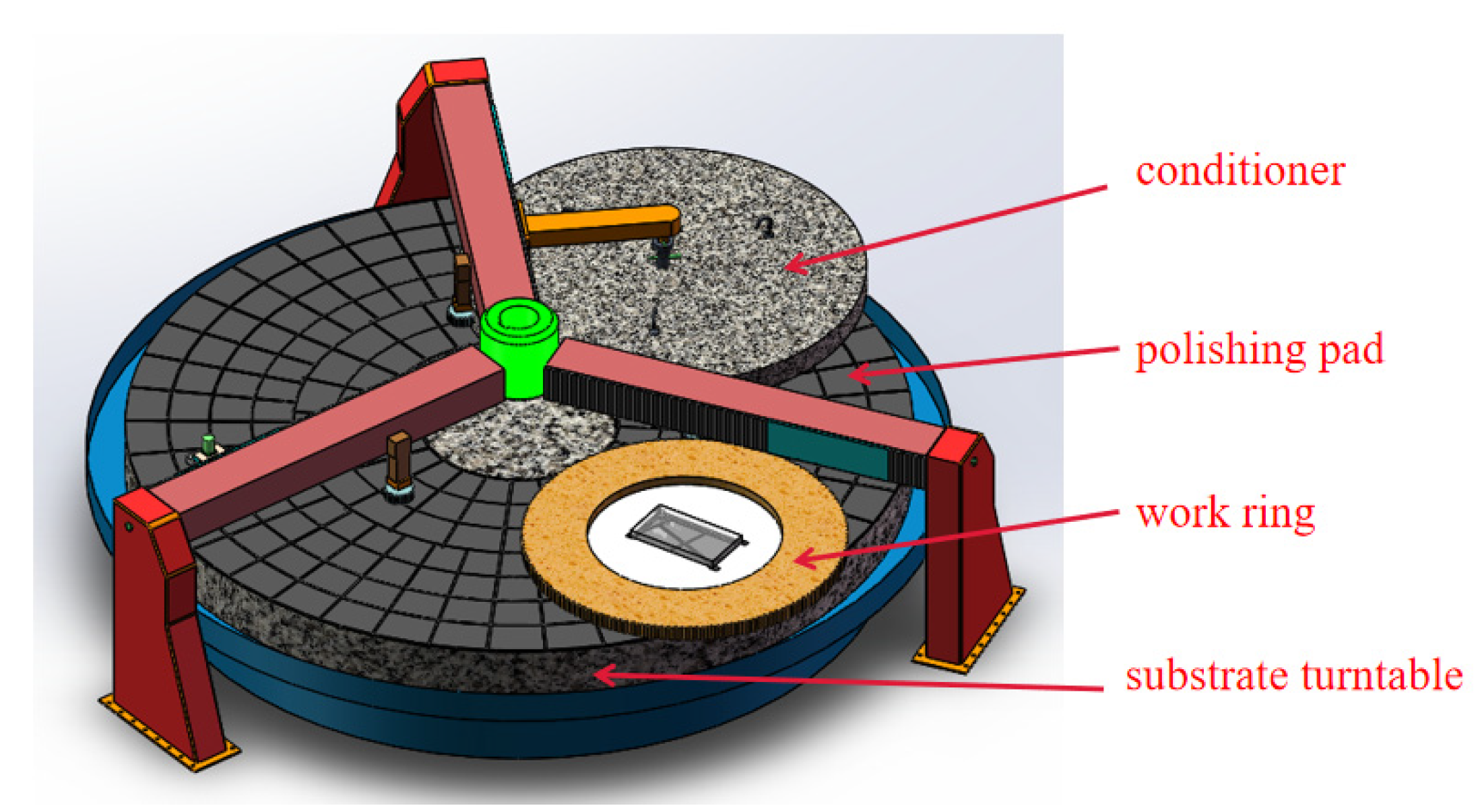
2. Lubrication Method in Continuous Polishing

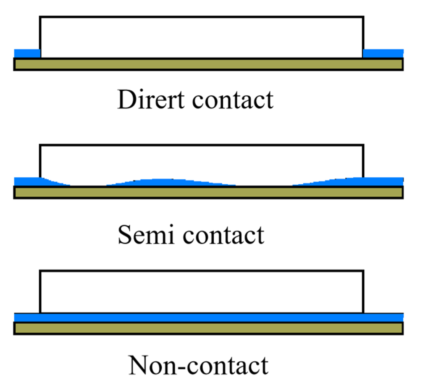
2.1. Lubrication Status Classification in Continuous Polishing

The continuous polishing machine uses a large substrate platen made from granite [22], as shown in Figure 1. An annular pitch layer is prepared on the granite plate surface as the grooves are cut into different shapes on the polishing lap surface to improve its fluidity and the slurry transmission. There are two work rings on one side of the annulus, and the inner diameter is equal to the annulus width. The plane optical elements to be polished are placed in these rings. There is a large circular truing tool called the ‘conditioner’ on the remaining portion of the annulus, which is substantially wider than the radius of the polishing pad. During the continuous polishing processes, the polishing lap, work rings and conditioner are driven by a servo motor. Abrasive slurry is sprayed on the surface of the polishing lap through the nozzle, and it transported to the bottom of the element through the groove. The surface finishing can be realized by the mechanical action of the polishing particles.
Different contact modes between the optical element and polishing lap directly determine the different lubrication characteristics, as shown in Figure 2. As a result, the polishing fluid has different flow characteristics between the element and polishing lap. Different polishing fluid flow characteristics affect the removal mechanism, removal rate and accuracy of continuous polishing.
The transformation between lubrication state and several kinds of states is the basis of theoretical analysis of the fluid lubrication. According to the formation mechanism and characteristics of the fluid lubrication film, the lubrication state can be divided into boundary lubrication, fluid film lubrication and mixture lubrication.
(1)
Boundary lubrication refers to the transition of the lubricant between the friction pairs from the internal friction between molecules to direct contact between two friction surfaces. In this lubrication state, the viscosity characteristics of the lubricant do not have effect on the lubrication. The lubrication function of the fluid film is weak and can be ignored, and there is more contact between the micro-convex bodies on the friction surface. The surface friction and wear characteristics are determined by the interaction among the lubricant, friction surface and properties of the boundary film. The load between the friction pairs is provided by the surface micro-convex body.
(2)
Fluid lubrication refers to the lubrication state in which the friction surface is separated by a continuous fluid film. In this state, the surface of the friction pair does not directly contact with each other and the contact wear does not occur.
(3)
Mixture lubrication refers to the coexistence of the boundary lubrication and fluid lubrication. In this state, the lubricating film is discontinuous, and is divided into fluid lubricating film and boundary lubricating film. On the one hand, the fluid lubrication film bears part of the load and produces viscous friction. On the other hand, the boundary lubrication film and the micro-convex body on the contact surface bear another part of the load, resulting in the dry friction on the contact surface. In addition, the mixture lubrication state is often unstable and fluctuates between the fluid film lubrication and boundary lubrication.

2.2. Judgment Method of Lubrication State of Continuous Polishing

In the state of the fluid film lubrication, when the load increases and the relative motion speed of the friction pair and lubricant viscosity decrease, the bearing capacity of the fluid film, thickness of the lubrication film and spacing between the friction surfaces decrease. If there is a certain amount of the micro-convex contact in the friction, this state may be transformed into the mixture lubrication. A judgment method is introduced below.
The calculation formula of the film thickness ratio is given in Equations (1) and (2).
ψ = h m / R q
R a = 4 ( R a 1 2 + R a 2 2 ) 1 2 / 3
where, hm is the minimum lubricating film thickness, Rq is the comprehensive surface roughness. Ra1, and Ra2 are the average deviations of the arithmetic contour of the surface roughness.
According to the calculation formula, when ψ ≤ 1, it is in the boundary lubrication state, and there are many micro-convex contacts in the friction pair. When 1 < ψ < 3, the film thickness ratio increases within this range, the fluid transits from the boundary lubrication to fluid lubrication, and the fluid film thickness increases. When ψ ≈ 3, for the high pair contact with a large load, it is in the state of full elastic hydrodynamic lubrication. When ψ > 3, it is in the state of complete fluid film lubrication. The thickness of the liquid film and roughness of the polishing lap are approximately 25 and 10 μm, respectively [23]. Therefore, the film thickness ratio of the continuous polishing ψ is equal to 2.5, which belongs to mixture lubrication. The numerical simulation model of the mixture lubrication will be established, and, then, the accuracy of the model will be verified by the experiments.

3. Numerical Model of Mixture Lubrication for Continuous Polishing

3.1. Load Sharing Theory

When the mixture lubrication is formed through continuous polishing, it is necessary to consider both the rough peak and liquid film in the contact area. According to the Johnson load thought [24], the total contact load FN is shared by the liquid film pressure Fh and rough peak force Fa on the contact surface, as given in Equation (3). The friction Ff is composed of the lubricating liquid film friction Ffh and rough peak friction Ffa, as shown in Equation (4).
F N = F h + F a
F f = F f h + F f a
Introducing the scale factor r, the liquid film bearing ratio is 1/r1, and the micro-convex body bearing ratio is 1/r2. The bearing ratio of the liquid film refers to the proportion of the pressure carried by the whole liquid film in the total optic load. The relation between these parameters can be expressed by Equations (5) and (6).
F h = F N / r 1 , F a = F N / r 2
1 r 1 + 1 r 2 = 1
On the contact interface, different micro-convex bodies have the same friction coefficient, and the friction of micro-convex bodies is expressed by Equation (7).
F f a = μ c F a = 1 r 2 F N μ c
The polishing fluid of the continuous polishing can be regarded as Newtonian fluid at a low speed [25]. The shear stress of the fluid is known from the Newton law of fluid viscosity, as shown in Equation (8).
τ = η u h
where τ is the shear stress, η is the viscosity of polishing solution, and u is the sliding speed.
Therefore, the friction coefficient of mixture lubrication can be calculated by Equation (9).
u f = F C F N = i = 1 N A C i τ C i ( r ˙ ) d A C i + 1 r 2 F N μ c F N = η u A H h F N + 1 r 2 μ c
where μc is the boundary friction coefficient, lubrication area is AH = AmonAr, Amon is the nominal contact area, Ar is the actual contact area, and h is the average liquid film thickness.

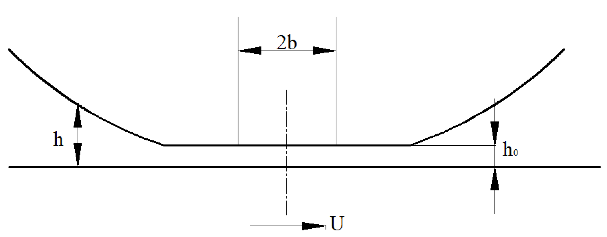
3.2. Calculation Method of Liquid Film Thickness

The basic concept of the lubrication is to solve Reynolds equation to reveal the distribution of the pressure in fluid lubrication film. The temperature difference in the annular polishing lubrication system is very small, so it is unnecessary to consider the change of the lubricant viscosity and density with the temperature. In addition to the isothermal conditions, the following assumptions should be used in the derivation:
(1)
The effect of the volume force, such as gravity or magnetic force is ignored. In addition to the theory of the electronic fluid or magnetic fluid lubrication, this assumption is usually reasonable.
(2)
The fluid has no sliding on the solid interface, that is, the velocity of the fluid particle attached to the interface is the same as that of the point on the interface.
(3)
In the direction along the thickness of the lubricating film, the change of the pressure is ignored. Because the film thickness is only less than one micron to tens of microns, in such a thin range, the pressure cannot change significantly. From this hypothesis, it can be inferred that the viscosity and density of the fluid do not change in the direction of film thickness.
(4)
Compared with the film thickness, the radius of the curvature of the support surface is large, and, accordingly, the change of velocity direction caused by the surface curvature can be ignored.
(5)
The lubricant is Newtonian fluid.
(6)
The flow is laminar, without vortex and turbulence.
(7)
Compared with the viscous force, the influence of inertial force can be ignored, including the inertial force of the fluid acceleration and centrifugal force of the fluid film bending.
Based on the above assumptions, the Reynolds equation under the isothermal conditions is given in Equation (10).
x ( ρ h 3 η p x ) + y ( ρ h 3 η p y ) = 12 x ( ρ U h ) + 12 y ( ρ V h ) + 12 ( ρ h ) t
where, ρ is the fluid density. U and V are the speeds of the optic and polishing lap, respectively.
U = ( U 1 + U 2 ) / 2 , V = ( V 1 + V 2 ) / 2
The pressure P is integrated in the whole lubricating film range, and the result is the bearing capacity of the lubricating film. For optical elements in the ring polishing, the bearing capacity is given in Equation (12).
W = p d x d y
Two dimensionless parameters are defined as Equation (13).
W ¯ = W E R , U ¯ = η 0 U E R
where W ¯ is the load parameter, and U ¯ is the speed parameter. In the definition of W ¯ , E is the equivalent elastic modulus, and it can be calculated by the elastic modulus E 1 , E 2 and Poisson’s ratio υ 1 and υ 2 of the two surfaces, as given in Equation (14).
1 E = 1 2 ( 1 υ 1 2 E 1 + 1 υ 2 2 E 2 )
In the definition of U ¯ , R is the equivalent radius of curvature, and it can be calculated by the radii R1 and R2 of the two contact surfaces, as given in Equation (15).
1 R = 1 R 1 + 1 R 2
The schematic diagram of the liquid film is show in Figure 3, where the fluid density ρ is assumed as a constant. The Reynolds equation can be derived from Equation (10) by assuming that the viscosity and density of the fluid do not change in the direction of film thickness, as shown in Equation (16).
d p d x = 12 η 0 U h h 0 h 3
where h0 is the actual film thickness at x = 0.
When h ¯ = h / R , p ¯ = p / E , x ¯ = x / b , Equation (16) can be rewritten into Equation (17).
d p ¯ d x ¯ = 48 ( W ¯ 2 π ) 1 / 2 U ¯ h ¯ h ¯ 0 h ¯ 3
The film thickness can be expressed by Equation (18).
h ¯ 0 = 1.95 ( E U ¯ ) 8 / 11 / W ¯ 1 / 11
The dimensional form is given in Equation (19).
h 0 = 1.95 ( a η 0 U ) 8 / 11 R 4 / 11 ( E / W ) 1 / 11
Equation (19) is the empirical formula of the average thickness of the liquid film in the contact area.
In the mixture lubrication problem, the actual thickness of the liquid film should also consider the elastic deformation and surface roughness of the polishing lap. Note that the sum of the elastic deformation of the two surfaces is δ and the roughness function is S(x). The calculation of the liquid film thickness is given in Equation (20).
h = h 0 + x 2 2 R + S ( x ) + δ
It is known from the elasticity that, for a semi-infinite body, when a concentrated force P uniformly distributed in the Y direction acts on the z-axis, the normal elastic deformation δ(x) at any point M with abscissa x is given in Equation (21).
δ ( x ) = 1 v 2 π E P ln x 2 1 + v π E p + C 0
where E is the elastic modulus, v is the Poisson’s ratio, and C0 is the constant. C0 and H0 are combined into one term, and the liquid film thickness h is obtained in Equation (22).
h c = h 0 + x 2 2 R 1 v 2 π E P ln x 2 1 + v π E P
When two rough surfaces come into contact with each other, Greenwood and Trip [26] deduced the equation of the total load by the micro-convex body, as given in Equation (23).
F h = 8 2 15 π n 2 β 1.5 σ s 2.5 E F ( H )
where n is the number of micro-convex bodies per unit area, β is the radius of micro-convex body, σ is the root mean square value of the surface roughness. F(H) can be calculated by Equation (24).
F ( H ) = 4.4086 × 10 5 ( 4 H ) 6.804
H = h c d d σ s
where dd is the distance between the average surface of the micro-convex body and plane of the polishing lap, which is about 1.15 σs.

3.3. Numerical Simulation Method of Mixture Lubrication

In order to calculate the friction coefficient of the mixture lubrication, it is necessary to obtain the liquid film thickness h and bearing ratio of the micro-convex body 1/r2. The liquid film pressure is calculated according to the liquid film bearing ratio, and the liquid film thickness is calculated according to the liquid film pressure. Calculation steps are as follows.
(1)
The initial parameters are set, including the viscosity η of the polishing solution and the characteristic values of the surface roughness of the polishing lap (n, β, σ).
(2)
The initial values of the liquid film bearing ratio r1 and micro-convex body bearing ratio r2 are set, and h0 is calculated according to the empirical formula.
(3)
The liquid film load W and dimensionless parameter in Equation (1) are calculated.
(4)
Calculate the liquid film thickness hc and load on the micro-convex body Fh according to Equation (3).
(5)
Calculate the load on the micro-convex body Fh1 according to Equation (23).
(6)
Judge whether the difference between the two ends of the load on the micro-convex body is less than 10−4.
(7)
If the friction coefficients r1 and r2 are substituted into the balance condition, the friction coefficient μ is obtained by substituting it into Equation (9). Otherwise, repeat steps (2)–(6) until the error converges.

3.4. Numerical Simulation Results of Mixture Lubrication

3.4.1. Calculation Results of Liquid Film Thickness

The relationship between the liquid film thickness and relative speed of the polishing lap is shown in Figure 4a. When the surface roughness of the polishing lap is constant, the thickness of the liquid film increases with the increase of the rotating speed of the polishing lap. This occurred because the increase of the polishing lap speed increases the flow rate of the polishing liquid. The relationship between the liquid film thickness and relative speed of the polishing lap is shown in Figure 4b. When the rotating speed of the polishing lap is constant, the thickness of the liquid film between the element and polishing lap increases with the increase of the surface roughness of the polishing lap. This occurred because the increase of the surface roughness of the polishing lap will make more polishing liquid flow between the element and polishing lap, resulting in the increase of the thickness of the liquid film.
The Influence of the total load on liquid film thickness is shown in Figure 5. When the roughness of the polishing pad is a constant, the thickness of the liquid film decreases with the increase of the optic load. This is because the contact area between the element and polishing lap becomes larger, which squeezes the flow space of the polishing liquid. When the roughness increases and the total load is a constant, the liquid film thickness still maintains an increase trend.

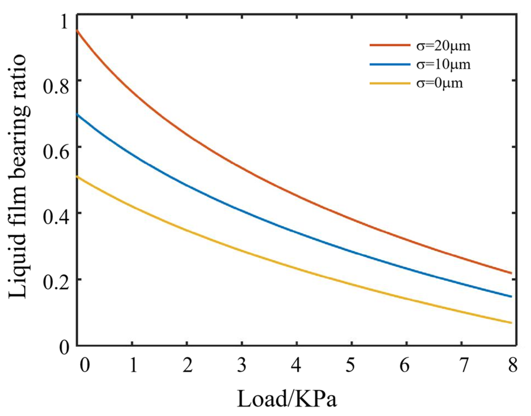
3.4.2. Calculation Results of Liquid Film Bearing Ratio

The relationship between the liquid film bearing ratio and polishing lap speed is shown in Figure 6, which indicates that, when the rotating speed is constant, the proportion of the liquid film load increases with the increase of the surface roughness of the polishing lap. This is because the rough surface increases the thickness of the liquid film.
When the surface roughness of the polishing lap is a constant, the proportion of the liquid film load will increase with the increase of the lap rotating speed. This is because the probability of the direct contact between the element and micro-convex body on the surface of the polishing lap decreases with the increase of the thickness of the liquid film. When the rotating velocity increases to a certain extent, the proportion of the liquid film load increases slowly and is close to 1. It indicates that the lubrication state is in hydrodynamic lubrication mode at this time. The element and polishing lap are completely separated by a continuous liquid film, and the load is completely borne by the liquid film.
The relationship between the liquid film bearing ratio and polishing load under different roughness is shown in Figure 7. When the rotating speed of the polishing lap is a constant, the proportion of the liquid film decreases with the increase of the total load, and gradually approaches zero. This is because when the contact area between the element and polishing lap increases, it squeezes the flow space of the polishing liquid and reduces the thickness of the liquid film. When the total load is a constant and the roughness increases, the liquid film thickness still increases.

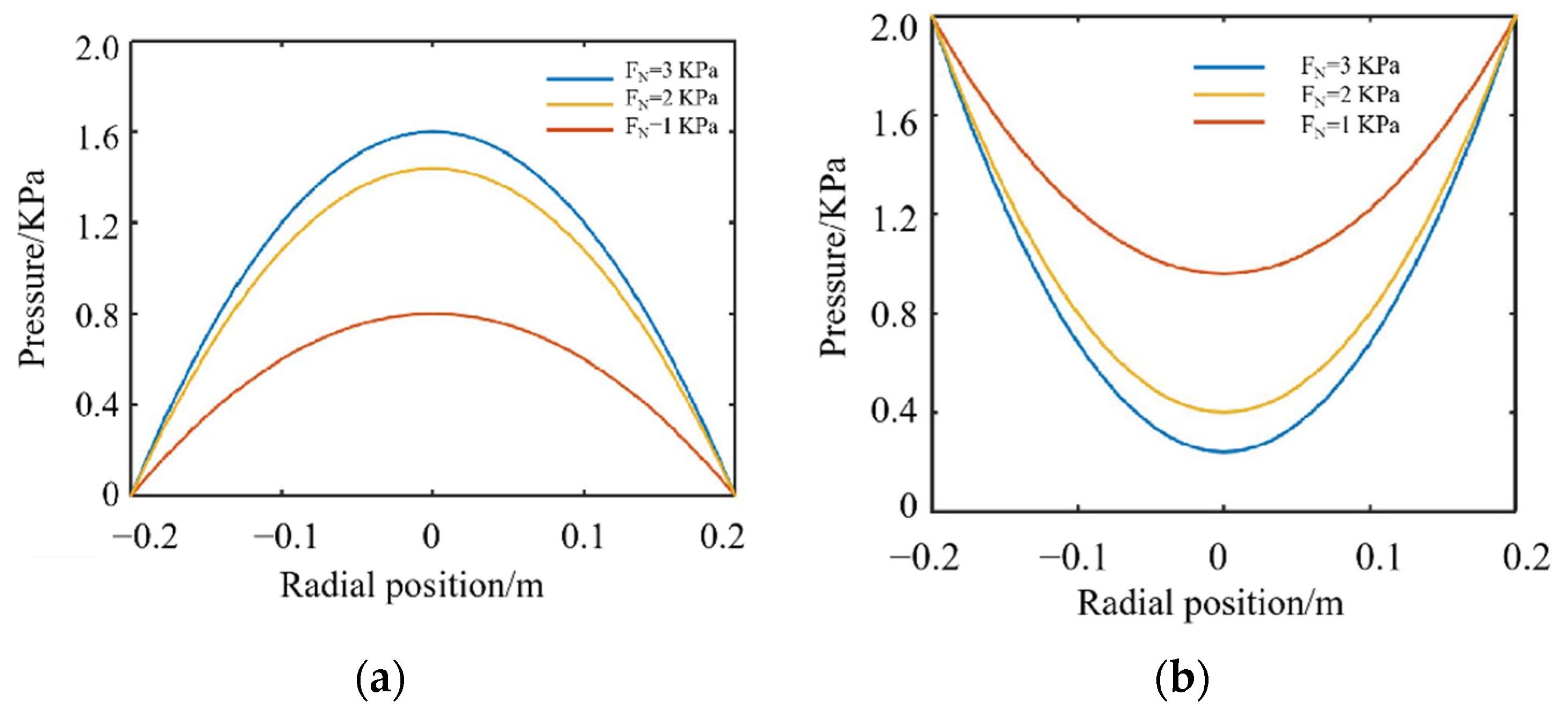
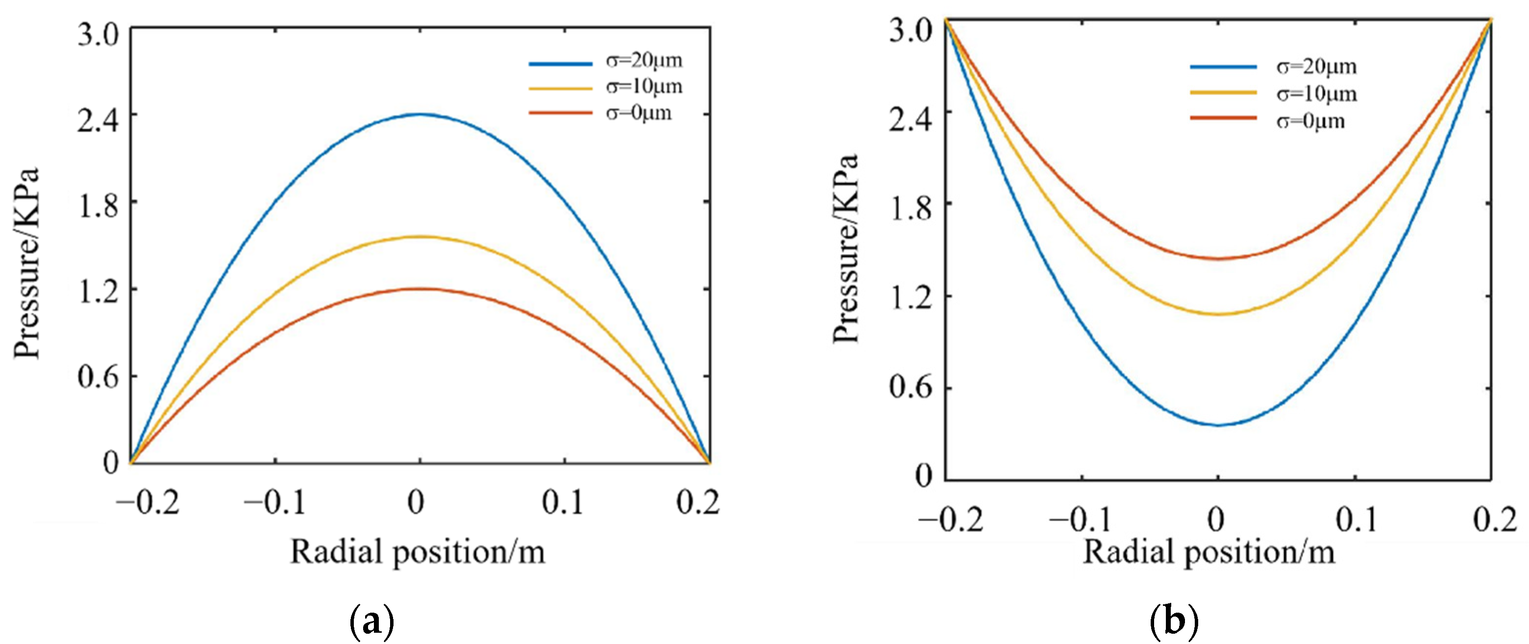
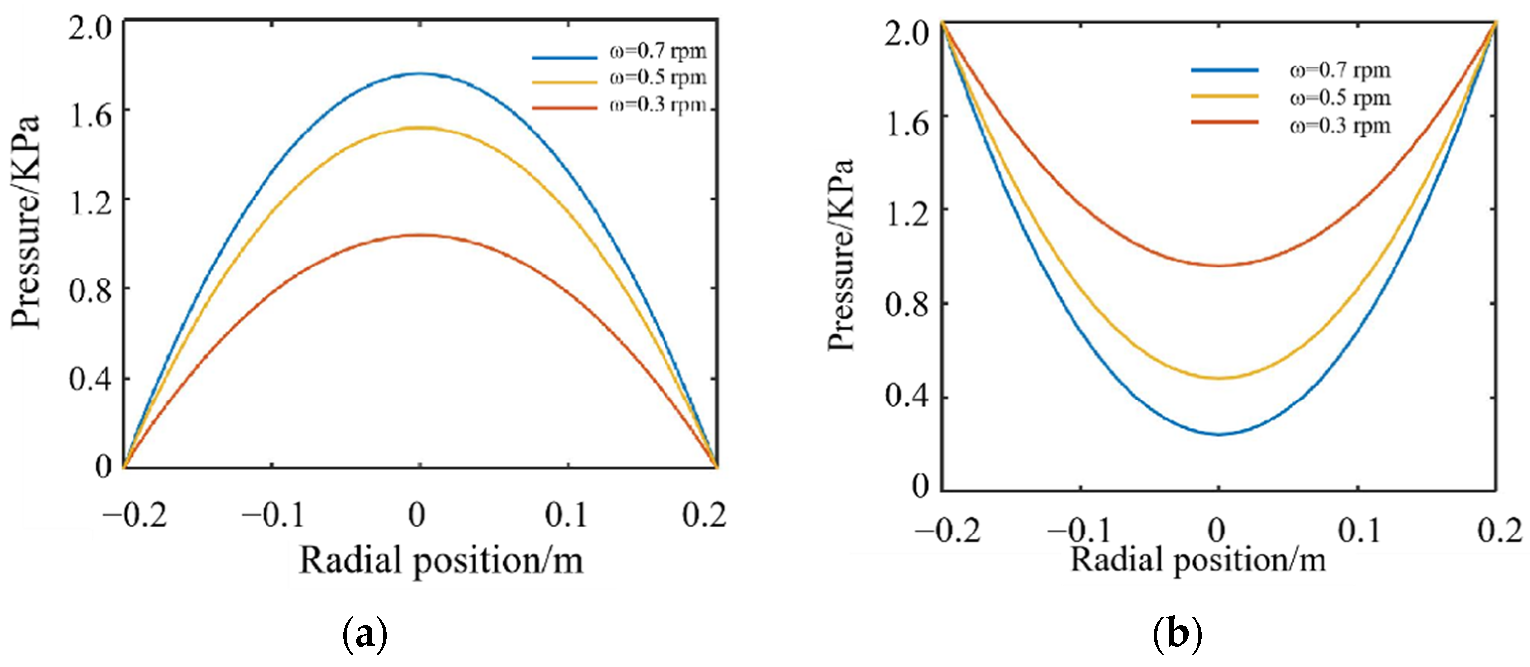
3.4.3. Calculation Results of Pressure Distribution

In continuous polishing, the optical element is removed by the friction with the polishing particles on the surface of the polishing lap. It is assumed that the load of the element is borne by the micro-convex body on the polishing lap and polishing fluid. The actual material removal is only related to the contact pressure on the surface of the polishing lap. Therefore, the actual polishing pressure of the element in the mixture lubrication mode is obtained by subtracting the liquid film pressure from the load of the optic. According to the simplified Reynolds Equation (16), the liquid film pressure distribution under different total loads is shown in Figure 8a. The micro-convex body bearing pressure distribution under different total loads is shown in Figure 8b. It can be seen from the figure that the distribution of the liquid film pressure is symmetrical around the center of the element, and the pressure in the center of the element is the highest. The maximum liquid film pressure increases with the increase of the external load. This is because, on the one hand, the increase of the overall pressure of the element leads to the increase of the liquid film pressure. On the other hand, due to the increase of the external load of the element, the thickness of the liquid film decreases and the bearing capacity of the liquid film is weakened. As a result, the maximum liquid film pressure increases slowly when the external load becomes large.
The distribution curve of the liquid film pressure along the horizontal direction is shown in Figure 9. It can be seen that the liquid film pressure increases with the roughness increase. This is because the roughness of the polishing lap surface enhances the flow of polishing liquid and increases the thickness of the liquid film. Thus, the loading force of the liquid film is increased, and the bearing capacity of the polishing liquid film is increased. At the same time, it can be seen that when the roughness increases, the maximum liquid film pressure increases faster, but at the same time, the liquid film pressure distribution becomes nonuniform, so the appropriate surface roughness of the polishing lap should be selected for polishing.
The liquid film pressure distribution under different lap rotating speeds is shown in Figure 10. It can be seen that the liquid film pressure is symmetrically distributed around the center of the element. The maximum liquid film pressure increases with the increase of the rotating speed of the polishing lap. It shows that higher polishing speed is not conducive to the uniform distribution of the liquid film pressure. When the polishing speed is large, the material removal rate of the optic is also larger, which is easy to damage the surface of the optical element. In order to ensure the surface quality, it is necessary to improve the roughness of the polishing pad and increase the average liquid film thickness to protect the surface of the optic.

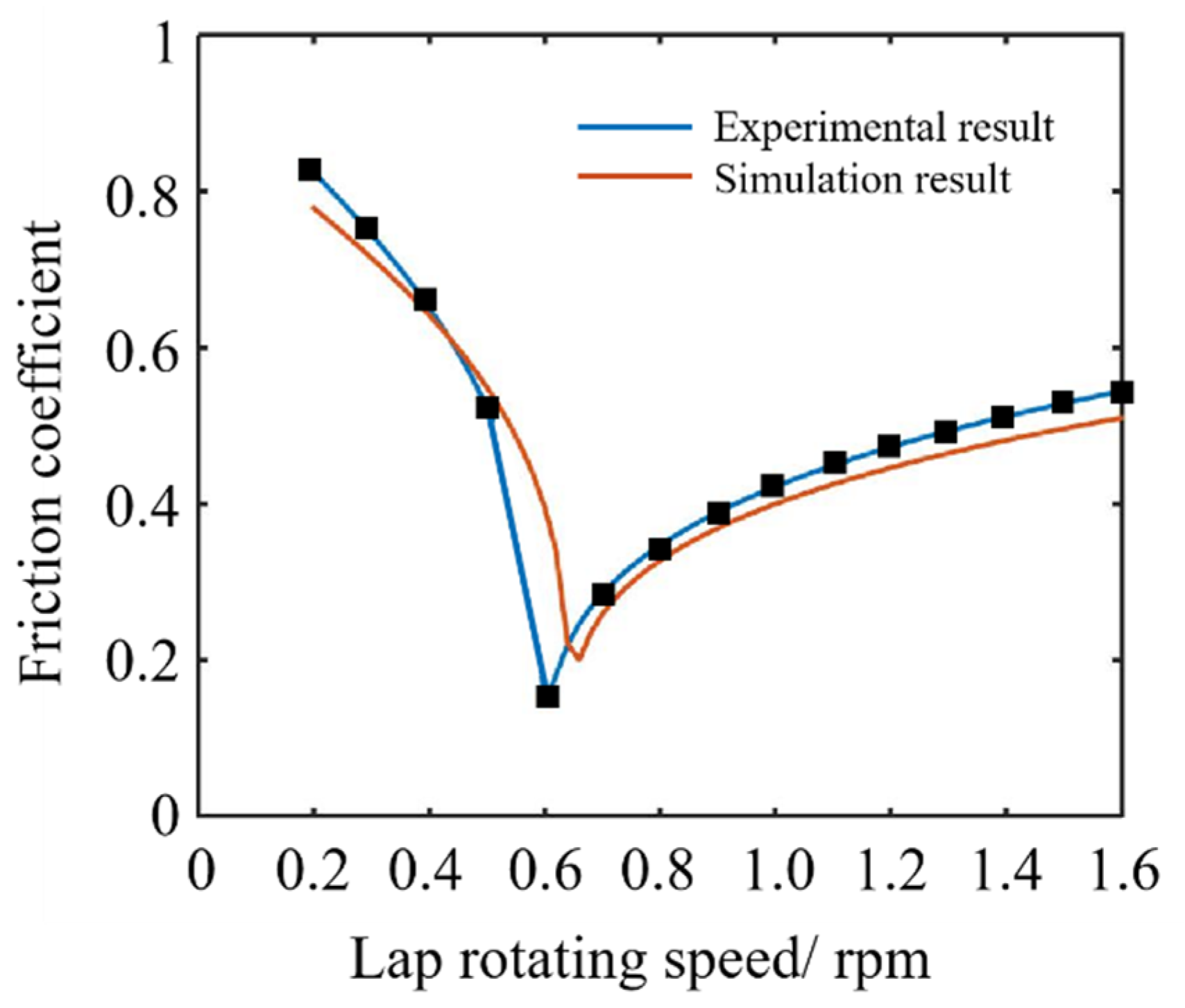
3.4.4. Friction Coefficient Calculation Results and Experimental Verification

To verify the accuracy of the numerical simulation results, the friction coefficient measurement experiments were carried out. Fpt-f1 friction stripping tester was used for the friction coefficient measurement test. The friction pair is fused quartz glass and asphalt block, and the polishing fluid is used for the lubrication. The friction coefficients of the friction pair at different rotating speeds are obtained. The numerical calculated and experimental results of the friction coefficient are as shown in Figure 11. The abscissa of the friction coefficient curve is the relative speed between the element and polishing lap, and the ordinate is the friction coefficient between the element and polishing lap. It can be seen that the friction coefficient curves obtained by the numerical calculation and experimental measurement are similar to the Stribeck curve. The friction coefficient decreases first and then increases with the increase of the relative speed. The numerical values of the two curves are also approximately equal in different lubrication zones, which verifies the correctness of the numerical results. At the same time, for the ring polishing process, the relative speed of the element and polishing lap is 0.3–0.5 rpm. In the figure, it belongs to the mixture lubrication area, which further proves that the lubrication mode of the annular polishing belongs to mixture lubrication.

4. Numerical Model Verification Experiment of Mixture Lubrication

4.1. Experimental Method

The surface shape measurement experiments before and after the surface shape machining of the annular polishing element are carried out, the material removal distribution in the process of the element polishing is obtained, and the accuracy of the pressure distribution calculated by the numerical model is verified. First, the liquid film pressure and bearing pressure distribution of the polishing lap are obtained through the calculation of the mixture lubrication numerical model. The material removal distribution is obtained according to Preston material removal equation of Equation (26) [27,28]. A fused quartz optical element with a size of 430 mm × 430 mm × 80 mm is selected for the experiment, and the distance between the element center and center of the polishing lap is 1.6 m. The average polishing pressure of the optical element is about 2.0 KPa. Material removal coefficient in Preston equation is equal to k = 4.73 × 10⁻¹³/Pa, and polishing time is t = 3 h. Different process parameters are selected for rotating speed and polishing lap roughness.
M R R = K P V

4.2. Experimental Result

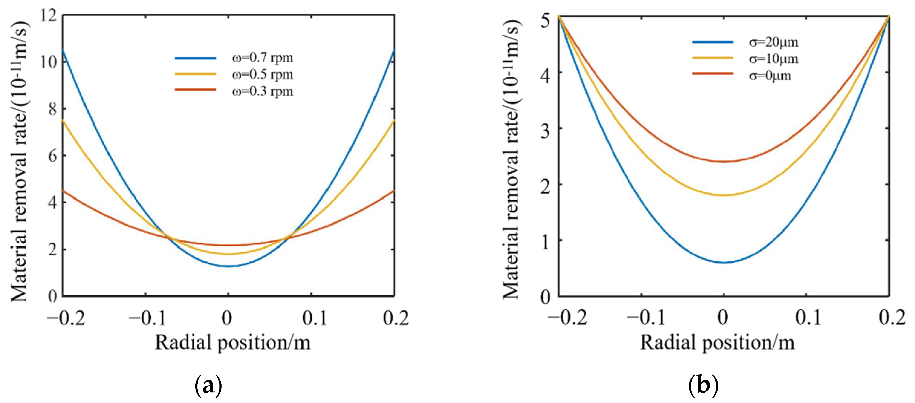
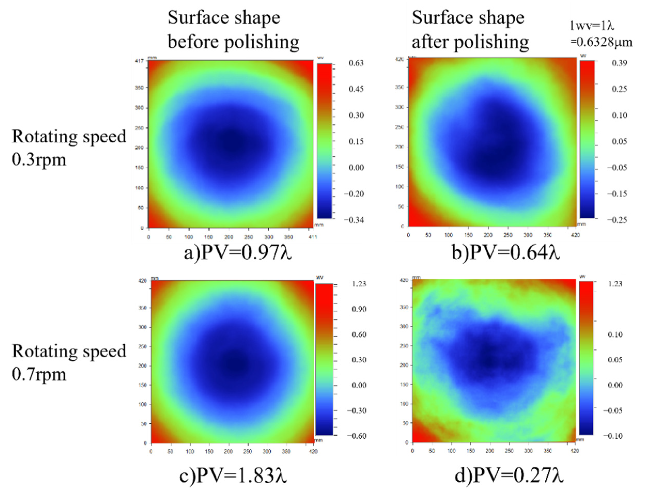
4.2.1. Influence of Different Rotating Speeds on Material Removal Uniformity

When the rotating speed of the polishing lap is changed, the result distribution of the material removal rate calculated according to the numerical simulation model is shown in Figure 12. When the rotating speed is 0.3 rpm, the difference of the material removal rate between the optic center and optic edge is 2.26 × 10⁻¹¹ m/s. When the polishing time is 3 h, the material removal is 0.23 μm, which is about 0.36 λ (1 λ = 0.6328 μm). When the rotating speed is 0.7 rpm, the difference of the material removal rate between the optic center and optic edge is 9.6 × 10⁻¹¹ m/s. When the polishing time is 3 h, the material removal is 1.03 μm, which is about 1.64 λ. When the polishing time is 3 h, the material removal is 0.23 μm, which is about 0.36 λ. When the rotating speed is 0.7 rpm, the difference of the material removal rate between the optic center and optic edge is 9.6 × 10⁻¹¹ m/s. When the polishing time is 3 h, the material removal is 1.03 μm, which is about 1.64 λ.
In the experiment, two optics with concave initial surface shape were polished at 0.3 and 0.7 rpm, respectively. Then, the surface shapes of the elements were measured after polishing for 3 h. The lowest point of the element is taken as the reference, and the difference of the material removal amount between the center and edge of the element is the subtraction of the surface shape before and after polishing. The initial surface shape and the processed surface shape of the elements are shown in Figure 13. It can be seen that when the rotating speed is 0.3 rpm, the optic edge material is removed by 0.33 λ more than the center, which is close to the simulated result. When the rotating speed is 0.7 rpm, the edge material of the optic is removed by 1.56 λ more than the center, which is also approximately equal to the calculated result. Thus, for the optical elements with concave shape, increasing the rotating speed can improve the surface flatness.
In conclusion, the use of low-speed process parameters is conducive to the uniformity of the material removal distribution, but is not conducive to the processing efficiency. High rotating speed will increase the material removal rate and make the surface shape of the element become more convex, which is suitable for the element whose initial surface shape is concave. Therefore, in the actual processing, it is necessary consider the surface shape of the initial element and select the appropriate speed parameters [29,30,31].

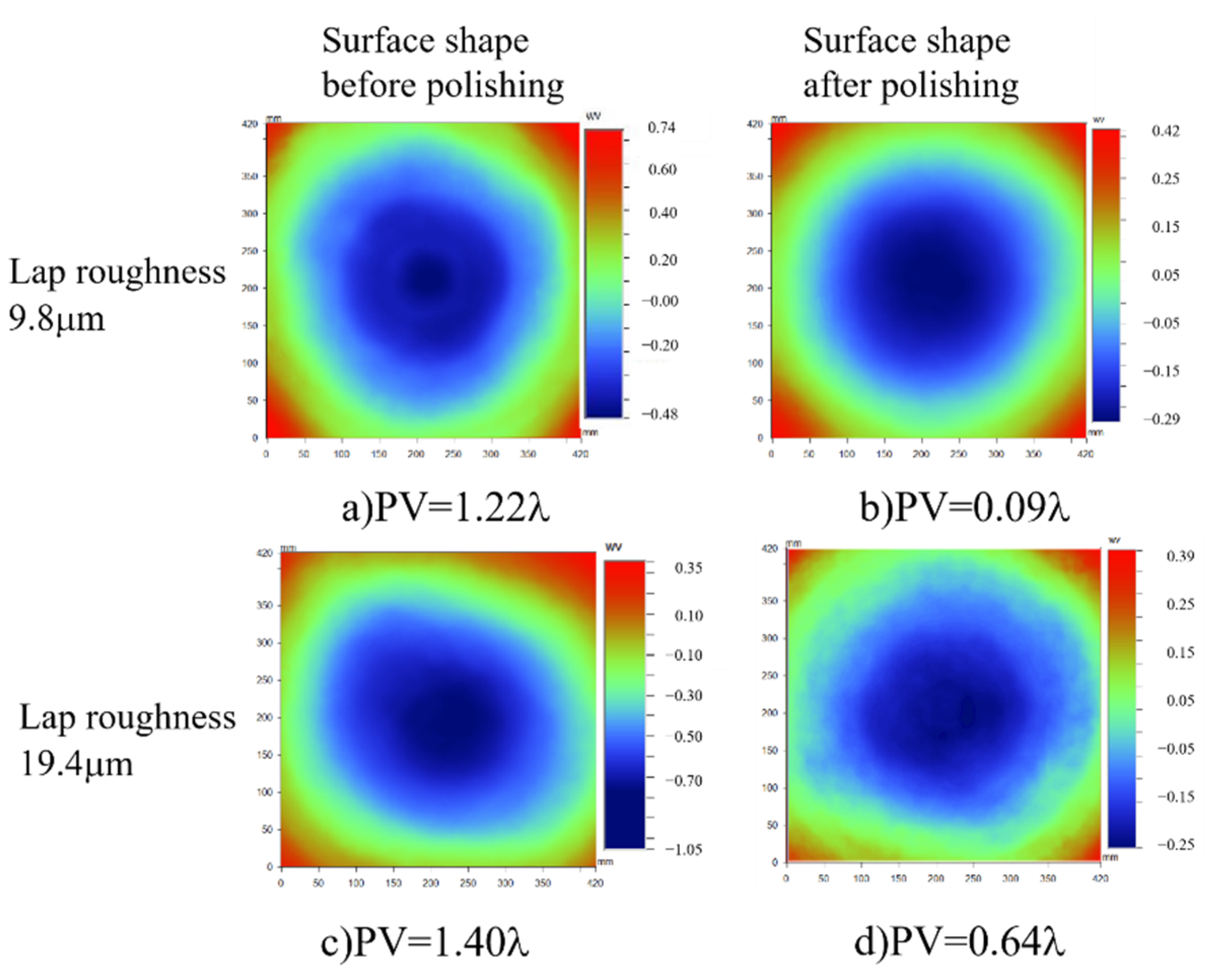
4.2.2. Influence of Different Polishing Lap Surface Roughness on Material Removal Uniformity

According to the calculation by the simulation model, when the surface roughness of the polishing lap is 10 μm, the difference of the material removal on the surface of the component after machining for 3 h is about 0.35 μm, which is about 0.53 λ. When the surface roughness of the polishing lap is 20 μm, the difference of element surface removal is about 0.49 μm, which is about 0.8 λ.
The surface roughness Ra of the polishing lap selected in the experiment is about 9.8 and 19.4 μm respectively. When the surface roughness of the polishing lap is 9.8 μm, the material removal difference between the optic edge and optic center is 0.33 μm, which is about 0.52 λ. When the surface roughness of the polishing lap is 19.4 μm, the material removal difference between the optic edge and optic center is 0.48 μm, which is about 0.76 λ. The surface shapes of the optic before and after polished are shown in Figure 14. Thus, when it is necessary to improve the material removal rate at the center, the polishing lap roughness should be increased [32].

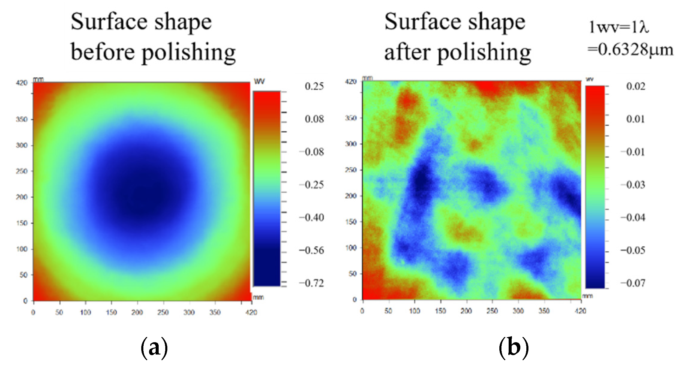
4.2.3. Optic Surface Shape Optimization Experiment

The final surface shape of the element can be actively controlled by adjusting the process parameter according to above experiments. A fused quartz optical element with a size of 430 mm × 430 mm × 80 mm is selected in the experiment, and its initial surface shape is 0.97 λ, as shown in Figure 15a. According to the calculation, when the material removal required for the element edge is 0.97 λ more than the center, the rotating speed of the polishing lap is selected as 0.5 rpm, and the surface roughness of the polishing lap is controlled to be 9.8 μm. The surface shape of the element obtained after polishing for 3 h is shown in Figure 15b. The material removal amount of the optic center is 0.88 λ, which is approximately equal to the calculated result, and the final surface shape PV is better than 0.1 λ.

5. Conclusions

Three possible contact modes between the optical elements and polishing lap in the annular polishing were analyzed. The lubrication mode in the continuous polishing belongs to mixture lubrication judged by calculating the film thickness ratio.
Based on the hydrodynamics theory, a numerical calculation model of the mixture lubrication in continuous polishing was developed. The influences of the polishing lap roughness, polishing speed and external load on the liquid film thickness, bearing ratio of the liquid film and polishing pressure distribution were revealed. The numerical simulation results indicated increasing the surface roughness of the polishing lap, polishing speed and optic load was not conducive to the uniformity of the pressure distribution. The numerical calculated and experimental results of the friction coefficient indicated that the friction coefficient decreased and then increased as rotating speed was increased.
The continuous polishing experiments of the fused quartz were carried out, and the influences of the surface roughness of the polishing lap and rotating speed on material removal rate of the optics were analyzed. The shape evolution rule of the optical element during the continuous polishing process was revealed. For fused silica elements, the material removal amount was calculated according to its initial surface shape. The surface shape accuracy was improved by selecting appropriate process parameters, such as the surface roughness and rotating speed of the polishing lap. By optimizing the process parameters, the surface PV of optical elements can be better than 0.1 λ.

Author Contributions

Conceptualization, F.Z. and C.L.; methodology, Y.W.; software, Y.W.; validation, Y.W., F.Z. and C.L.; formal analysis, Y.W.; investigation, Y.W. and C.L.; resources, Y.W.; data curation, Y.W.; writing—original draft preparation, Y.W.; writing—review and editing, C.L. and F.Z.; visualization, Y.W.; funding acquisition, C.L. and F.Z. All authors have read and agreed to the published version of the manuscript.

Funding

This research was funded by the National Natural Science Foundation of China (52005134, 51975154), Self-Planned Task (No. SKLRS202214B) of State Key Laboratory of Robotics and System (HIT), China Postdoctoral Science Foundation (2020M670901), Heilongjiang Postdoctoral Fund (LBH-Z20016), Open Fund of ZJUT Xinchang Research Institute, and Fundamental Research Funds for the Central Universities and The APC was funded by the National Natural Science Foundation of China (51975154).

Institutional Review Board Statement

Not applicable.

Informed Consent Statement

Not applicable.

Data Availability Statement

The study did not report any data.

Conflicts of Interest

The authors declare no conflict of interest.

References

  1. Zhang, Y.; Wang, Q.; Li, C.; Piao, Y.; Hou, N.; Hu, K. Characterization of surface and subsurface defects induced by abrasive machining of optical crystals using grazing incidence X-ray diffraction and molecular dynamics. J. Adv. Res. 2022, 36, 51–61. [Google Scholar] [CrossRef] [PubMed]
  2. Qu, S.; Yao, P.; Gong, Y.; Yang, Y.; Chu, D.; Zhu, Q. Modelling and grinding characteristics of unidirectional C–SiCs. Ceram. Int. 2022, 48, 8314–8324. [Google Scholar] [CrossRef]
  3. Li, C.; Piao, Y.; Meng, B.; Zhang, Y.; Li, L.; Zhang, F. Anisotropy dependence of material removal and deformation mechanisms during nanoscratch of gallium nitride single crystals on (0001) plane. Appl. Surf. Sci. 2022, 578, 152028. [Google Scholar] [CrossRef]
  4. Liao, D.; Xie, R.; Hou, J.; Chen, X.; Zhong, B. A polishing process for nonlinear optical crystal flats based on an annular polyurethane pad. Appl. Surf. Sci. 2012, 258, 8552–8557. [Google Scholar] [CrossRef]
  5. Atuchin, V.V.; Maklakova, N.Y.; Pokrovsky, L.D.; Semenenko, V.N. Restoration of KTiOPO4 surface by annealing. Opt. Mater. 2003, 23, 363–367. [Google Scholar] [CrossRef]
  6. Atuchin, V.V.; Kesler, V.G.; Kokh, A.E.; Pokrovsky, L.D. X-ray photoelectron spectroscopy study of β-BaB2O4 optical surface. Appl. Surf. Sci. 2004, 223, 352–360. [Google Scholar] [CrossRef]
  7. Ramana, C.V.; Atuchin, V.V.; Becker, U.; Ewing, R.C.; Isaenko, L.I.; Khyzhun, O.Y.; Zhurkov, S.A. Low-energy Ar+ ion-beam-induced amorphization and chemical modification of potassium titanyl arsenate (001) crystal surfaces. J. Phys. Chem. C 2007, 111, 2702–2708. [Google Scholar] [CrossRef]
  8. Korobeishchikov, N.G.; Nikolaev, I.V.; Roenko, M.A.; Atuchin, V.V. Precise sputtering of silicon dioxide by argon cluster ion beams. Appl. Phys. A 2018, 124, 833. [Google Scholar] [CrossRef]
  9. Xie, R.; Zhao, S.; Liao, D.; Chen, X.; Wang, J.; Xu, Q. Numerical simulation and experimental study of surface waviness during full aperture rapid planar polishing. Int. J. Adv. Manuf. Technol. 2018, 97, 3273–3282. [Google Scholar] [CrossRef]
  10. Luo, H.; Ajmal, K.M.; Liu, W.; Yamamura, K.; Deng, H. Polishing and planarization of single crystal diamonds: State-of-the-art and perspectives. Int. J. Extrem. Manuf. 2021, 3, 022003. [Google Scholar] [CrossRef]
  11. Zhang, Z.; Jin, Z.; Mu, Q.; Yang, H.; Han, X. Optimization of CMP solution for yttrium aluminum garnet crystal. Diam. Abras. Eng. 2021, 41, 82–88. [Google Scholar]
  12. Li, C.; Li, X.; Huang, S.; Li, L.; Zhang, F. Ultra-precision grinding of Gd3Ga5O12 crystals with graphene oxide coolant: Material deformation mechanism and performance evaluation. J. Manuf. Processes 2021, 61, 417–427. [Google Scholar] [CrossRef]
  13. Li, C.; Piao, Y.; Hu, Y.; Wei, Z.; Li, L.; Zhang, F. Modelling and experimental investigation of temperature field during fly-cutting of KDP crystals. Int. J. Mech. Sci. 2021, 210, 106751. [Google Scholar] [CrossRef]
  14. Chang, A. The effect of slurry film thickness variation in chemical mechanical polishing (CMP) of patterned oxide wafers. In Proceedings of the VMIC Conference 2000, Santa Clara, CA, USA; 2000; pp. 112–114. Available online: https://jglobal.jst.go.jp/en/detail?JGLOBAL_ID=200909054958270070 (accessed on 16 May 2022).
  15. Runnels, S.R.; Renteln, P. Modeling the effect of polish pad deformation on wafer surface stress distributions during chemical-mechanical polishing. In Proceedings of the Third International Symposium on Interconnects, Contact Metallization and Multilevel Metallization, 183rd Meeting of the Elecrochemical Society, Honolulu, HI, USA, 19–21 May 1993. [Google Scholar]
  16. Li, C.; Piao, Y.; Meng, B.; Hu, Y.; Li, L.; Zhang, F. Phase transition and plastic deformation mechanisms induced by self-rotating grinding of GaN single crystals. Int. J. Mach. Tools Manuf. 2022, 172, 103827. [Google Scholar] [CrossRef]
  17. Terrell, E.J.; Higgs, C.F. Hydrodynamics of slurry flow in chemical mechanical polishing: A review. J. Electrochem. Soc. 2006, 153, K15. [Google Scholar] [CrossRef]
  18. Waechter, D.; Dambon, O.; Klocke, F. Analysis and modeling of tribology effects in conventional glass polishing. In Optical Manufacturing and Testing X; International Society for Optics and Photonics: Bellingha, EA, USA, 2013; Volume 8838, p. 88380V. [Google Scholar]
  19. Sundararajan, S.; Thakurta, D.G.; Schwendeman, D.W.; Murarka, S.P.; Gill, W.N. Two-dimensional wafer-scale chemical mechanical planarization models based on lubrication theory and mass transport. J. Electrochem. Soc. 1999, 146, 761. [Google Scholar] [CrossRef]
  20. Kim, A.T.; Seok, J.; Tichy, J.A.; Cale, T.S. A multiscale elastohydrodynamic contact model for CMP. J. Electrochem. Soc. 2003, 150, G570. [Google Scholar] [CrossRef]
  21. Tichy, J. Contact Mechanics and Lubrication Hydrodynamics of Chemical-Mechanical Planarization; Tribology Series; Elsevier: Amsterdam, The Netherland, 2001; Volume 39, pp. 63–68. [Google Scholar]
  22. Liao, D.; Ren, L.; Zhang, F.; Wang, J.; Xu, Q. Kinematic model for material removal distribution and surface figure in full-aperture polishing. Appl. Opt. 2018, 57, 588–593. [Google Scholar] [CrossRef]
  23. Qin, K.; Moudgil, B.; Park, C.W. A chemical mechanical polishing model incorporating both the chemical and mechanical effects. Thin Solid Film. 2004, 446, 277–286. [Google Scholar] [CrossRef]
  24. Johnson, K.L.; Greenwood, J.A.; Poon, S.Y. A simple theory of asperity contact in elastohydro-dynamic lubrication. Wear 1972, 19, 91–108. [Google Scholar] [CrossRef]
  25. Habchi, W.; Eyheramendy, D.; Bair, S.; Vergne, P.; Morales-Espejel, G. Thermal elastohydrodynamic lubrication of point contacts using a Newtonian/generalized Newtonian lubricant. Tribol. Lett. 2008, 30, 41–52. [Google Scholar] [CrossRef]
  26. Greenwood, J.A.; Tripp, J.H. The contact of two nominally flat rough surfaces. Proc. Inst. Mech. Eng. 1970, 185, 625–633. [Google Scholar] [CrossRef]
  27. Guo, J.; Shi, X.; Song, C.; Niu, L.; Cui, H.; Guo, X.; Kang, R. Theoretical and experimental investigation of chemical mechanical polishing of W–Ni–Fe alloy. Int. J. Extrem. Manuf. 2021, 3, 025103. [Google Scholar] [CrossRef]
  28. Xu, J.; Kang, R.; Dong, Z.; Wang, Z. Review on chemical mechanical polishing of silicon wafers. Diam. Abras. Eng. 2020, 40, 24–33. [Google Scholar]
  29. Li, C.; Wu, Y.; Li, X.; Ma, L.; Zhang, F.; Huang, H. Deformation characteristics and surface generation modelling of crack-free grinding of GGG single crystals. J. Mater. Process. Technol. 2020, 279, 116577. [Google Scholar] [CrossRef]
  30. Sun, Y.; Jin, L.; Gong, Y.; Wen, X.; Yin, G.; Wen, Q.; Tang, B. Experimental evaluation of surface generation and force time-varying characteristics of curvilinear grooved micro end mills fabricated by EDM. J. Manuf. Processes 2022, 73, 799–814. [Google Scholar] [CrossRef]
  31. Li, C.; Hu, Y.; Huang, S.; Meng, B.; Piao, Y.; Zhang, F. Theoretical model of warping deformation during self-rotating grinding of YAG wafers. Ceram. Int. 2022, 48, 4637–4648. [Google Scholar] [CrossRef]
  32. Cheng, Z.; Gao, H.; Liu, Z.; Guo, D. Investigation of the trajectory uniformity in water dissolution ultraprecision continuous polishing of large-sized KDP crystal. Int. J. Extrem. Manuf. 2020, 2, 045101. [Google Scholar] [CrossRef]
Figure 1. Continuous polishing machine.
Crystals 12 00736 g001
Figure 2. Contact modes between the optical element and polishing lap.
Crystals 12 00736 g002
Figure 3. Schematic diagram of the liquid film.
Crystals 12 00736 g003
Figure 4. Influence of rotating speed and lap roughness on liquid film thickness. (a) Liquid film thickness vs. rotating speed (b) Liquid film thickness vs. lap roughness.
Crystals 12 00736 g004
Figure 5. Influence of total load on liquid film thickness.
Crystals 12 00736 g005
Figure 6. Relationship between liquid film bearing ratio and velocity under different roughness.
Crystals 12 00736 g006
Figure 7. Relationship between liquid film bearing ratio and element pressure under different lap roughness.
Crystals 12 00736 g007
Figure 8. Distribution of liquid film pressure along horizontal direction under different external loads. (a) Liquid film pressure distribution (b) Polishing pressure distribution.
Crystals 12 00736 g008
Figure 9. Liquid film pressure distribution along the radial direction of the element under different roughness. (a) Liquid film pressure distribution; (b) Polishing pressure distribution.
Crystals 12 00736 g009
Figure 10. Relationship between liquid film pressure distribution and rotating speed. (a) Liquid film pressure distribution; (b) Polishing pressure distribution.
Crystals 12 00736 g010
Figure 11. Experimental and calculated results of friction coefficient.
Crystals 12 00736 g011
Figure 12. Factors affecting material removal rate. (a) Effect of rotating speed on material removal rate (b) Effect of roughness on material removal rate.
Crystals 12 00736 g012
Figure 13. Experiment of influence law of rotating speed on element surface shape. (a) Rotating speed is 0.3 rpm before polishing, (b) rotating speed is 0.3 rpm after polishing, (c) rotating speed is 0.7 rpm before polishing and (d) rotating speed is 0.7 rpm after polishing.
Crystals 12 00736 g013
Figure 14. Influence law of roughness on element surface shape. (a) Lap roughness is 9.8 μm before polishing, (b) lap roughness is 9.8 μm after polishing, (c) lap roughness is 19.4 μm before polishing and (d) lap roughness is 19.4 μm after polishing.
Crystals 12 00736 g014
Figure 15. Experimental results of element surface shape measurement. (a) PV = 0.9 7λ; (b) PV = 0.09 λ.
Crystals 12 00736 g015
Publisher’s Note: MDPI stays neutral with regard to jurisdictional claims in published maps and institutional affiliations.

