
Iodine Doping Implementation Effect on the Electrical Response in Metallophthalocyanines (M = Cu, Co, Zn), for Electronic and Photovoltaic Applications

 , ,
, ,
Abstract
:1. Introduction
2. Theoretical Calculations
3. Materials and Methods
4. Results and Discussion
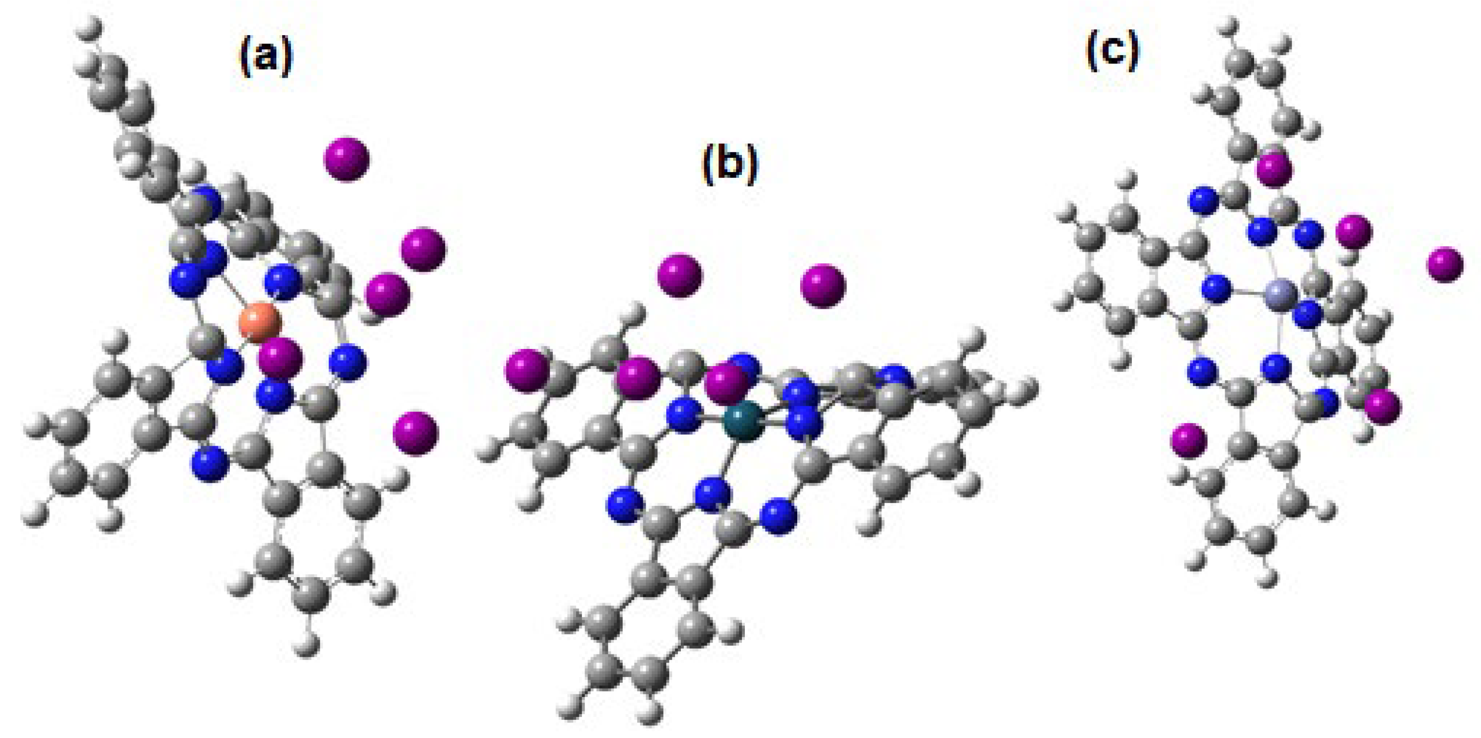
4.1. DFT Calculations
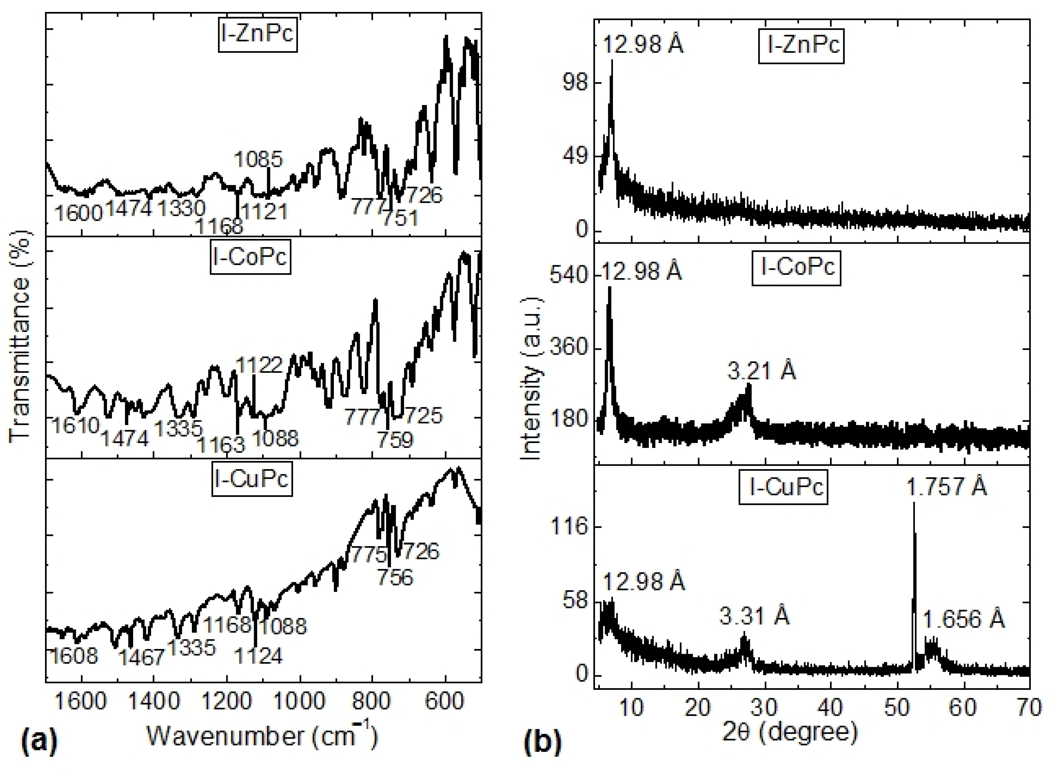
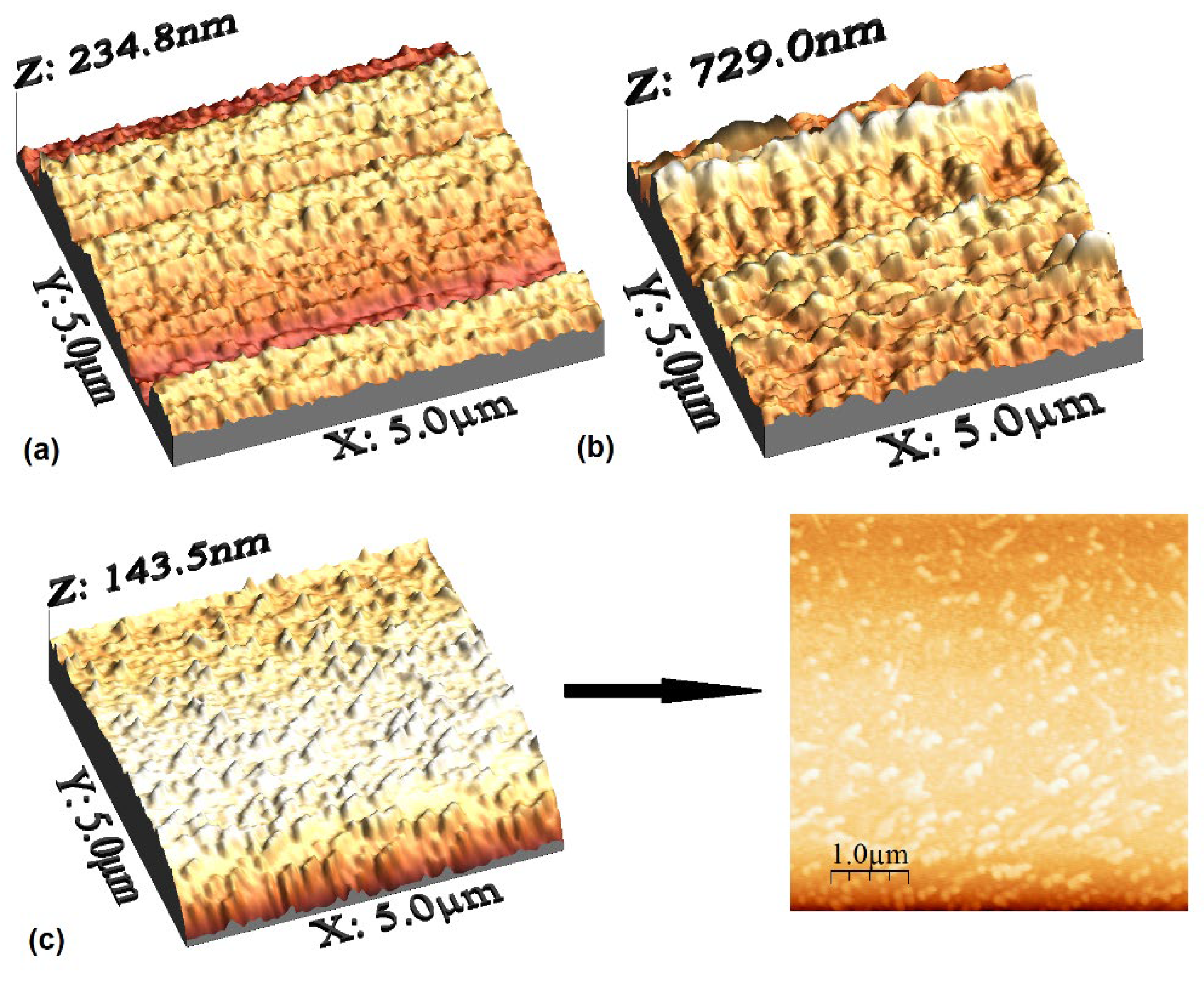
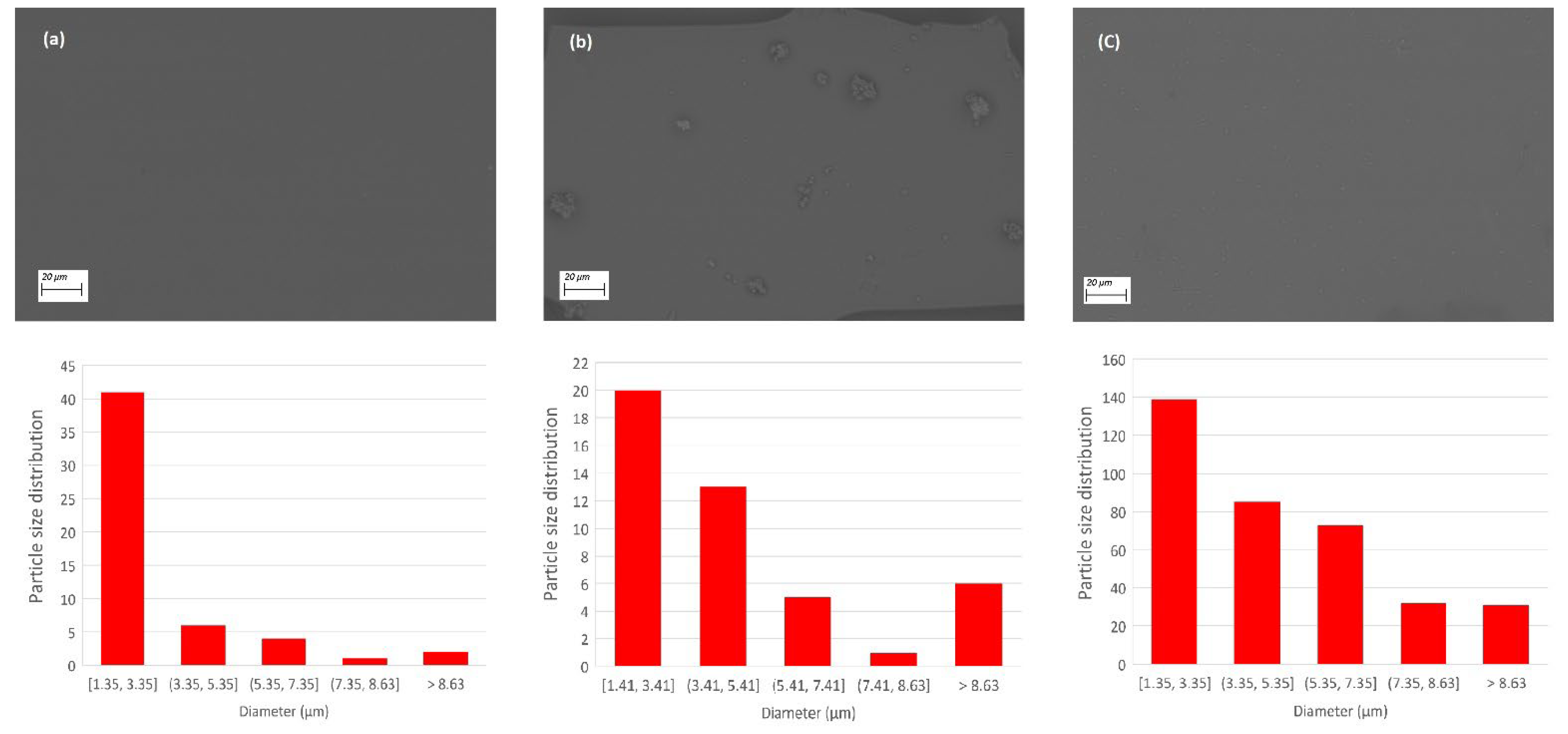
4.2. Deposit and Characterization of Thin Films
5. Conclusions
Supplementary Materials
Author Contributions
Funding
Institutional Review Board Statement
Informed Consent Statement
Data Availability Statement
Acknowledgments
Conflicts of Interest
References
- Roco, M.C.; Bainbridge, W.S. Societal implications of nanoscience and nanotechnology: Maximizing human benefit. J. Nanopart. Res. 2005, 7, 1–13. [Google Scholar] [CrossRef]
- Vidor, F.F.; Meyers, T.; Hilleringmann, U. Flexible Electronics: Integration Processes for Organic and Inorganic Semiconductor-Based Thin-Film Transistors. Electronics 2015, 4, 480–506. [Google Scholar] [CrossRef] [Green Version]
- Krishna, N.V.; Bhavani, B.; Mrinalini, M.; Srivishnu, K.S.; Giribabu, L.; Prasanthkumar, S. Bulk electrolysis of Zn-phthalocyanine unveils self-assembled nanospheres via anion binding. Curr. Appl. Phys. 2020, 20, 777–781. [Google Scholar] [CrossRef]
- Ghadari, R.; Sabri, A.; Saei, P.-S.; Kong, F.-T.; Marques, H.M. Phthalocyanine-silver nanoparticle structures for plasmon-enhanced dye sensitized solar cells. Sol. Energy 2020, 198, 283–294. [Google Scholar] [CrossRef]
- De la Torre, G.; Claessens, C.G.; Torres, T. Phthalocyanines: Old dyes, new materials. Putting color in nanotechnology. Chem. Commun. 2007, 2000–2015. [Google Scholar] [CrossRef] [PubMed]
- Soliman, I.M.; El-Nahass, M.M.; Khalifa, B.A. Characterization and photovoltaic performance of organic device based on AlPcCl/p-Si heterojunction. Synth. Met. 2015, 209, 55–59. [Google Scholar] [CrossRef]
- Khatib, N.; Boudjema, B.; Maitrot, M.; Chermette, H.; Porte, L. Electronic structure of zinc phthalocyanine. Can. J. Chem. 1988, 66, 2313–2324. [Google Scholar] [CrossRef]
- Blochwitz, J.; Pfeiffer, M.; Fritz, T.; Leo, K. Low voltage organic light emitting diodes featuring doped phthalocyanine as hole transport material. Appl. Phys. Lett. 1998, 73, 729. [Google Scholar] [CrossRef]
- Tran, N.L. A Fundamental Study on Analyte Adsorption onto Metallophthalocyanines; University of California: San Diego, CA, USA, 2008; pp. 1–70. Available online: https://escholarship.org/uc/item/0gw4v1jz (accessed on 7 July 2022).
- Janczak, J. Solvothermal modification of magnesium phthalocyanine. Inorg. Chim. Acta 2018, 478, 88–103. [Google Scholar] [CrossRef]
- Borovkov, N.Y.; Odintsova, E.G.; Petrenko, V.E.; Kolker, A.M. Amine-assisted solubilization of unsubstituted zinc phthalocyanine for film deposition purposes. RSC Adv. 2019, 9, 33969–33975. [Google Scholar] [CrossRef] [Green Version]
- Sorrenti, E.; Ball, V.; Del Frari, D.; Arnoult, C.; Toniazzo, V.; Ruch, D. Incorporation of Copper (II) Phtalocyanines as Model Dyes in Exponentially Growing Polyelectrolyte Multilayer Films: A Multiparametric Investigation. J. Phys. Chem. C 2011, 115, 8248–8259. [Google Scholar] [CrossRef]
- Ortí, E.; Brédas, J.L. Electronic structure of metal-free phthalocyanine: A valence effective Hamiltonian theoretical study. J. Chem. Phys. 1988, 89, 1009. [Google Scholar] [CrossRef] [Green Version]
- Leal, L.A.; da Cunha, W.F.; Ribeiro Junior, L.A.; Pereira, T.L.; Blawid, S.M.; de Sousa Junior, R.T.; da Silva Filho, D.A. Optical and electronic structure description of metal-doped phthalocyanines. J. Mol. Model. 2017, 23, 172. [Google Scholar] [CrossRef]
- Ali, H.E.A.; Altındal, A.; Altun, S.; Odabas, Z. Highly efficient dye-sensitized solar cells based on metal-free and copper(II) phthalocyanine bearing 2-phenylphenoxy moiety. Dyes Pigm. 2015, 124, 180–187. [Google Scholar] [CrossRef]
- Mali, S.S.; Dalavi, D.S.; Bhosale, P.N.; Betty, C.A.; Chauhan, A.K.; Patil, P.S. Electro-optical properties of copper phthalocyanines (CuPc) vacuum deposited thin films. RSC Adv. 2012, 2, 2100–2104. [Google Scholar] [CrossRef]
- Klyamer, D.D.; Sukhikh, A.S.; Gromilov, S.A.; Kruchinin, V.N.; Spesivtsev, E.V.; Hassan, A.K.; Basova, T.V. Influence of Fluorosubstitution on the Structure of Zinc Phthalocyanine Thin Films. Macroheterocycles 2018, 11, 304–311. [Google Scholar] [CrossRef]
- Sehlotho, N.; Nyokong, T. Zinc phthalocyanine photocatalyzed oxidation of cyclohexene. J. Mol. Catal. A Chem. 2004, 219, 201–207. [Google Scholar] [CrossRef]
- Madhuri, K.P.; John, N.S.; Angappane, S.; Santra, P.K.; Bertram, F. Influence of iodine doping on the structure, morphology, and physical properties of manganese phthalocyanine thin films. J. Phys. Chem. C 2018, 122, 28075–28084. [Google Scholar] [CrossRef]
- Ahmida, M.; Larocque, R.; Ahmed, M.S.; Vacaru, A.; Donnio, B.; Guillon, D.; Eichhorn, S.H. Halide effect in electron rich and deficient discotic phthalocyanines. J. Mater. Chem. 2010, 20, 1292–1303. [Google Scholar] [CrossRef]
- Krull, C.; Robles, R.; Mugarza, A.; Gambardella, P. Site- and orbital-dependent charge donation and spin manipulation in electron-doped metal phthalocyanines. Nat. Mater. 2013, 12, 337–343. [Google Scholar] [CrossRef]
- Case, D.A.; Darden, T.A.; Cheatham, T.E.; Simmerling, C.L.; Wang, J.; Duke, R.E.; Luo, R.; Walker, R.C.; Zhang, W.; Merz, K.M.; et al. AMBER 11; University of California: San Francisco, CA, USA, 2010. [Google Scholar]
- Valiev, M.; Bylaska, E.J.; Govind, N.; Kowalski, K.; Straatsma, T.P.; van Dam, H.J.J.; Wang, D.; Nieplocha, J.; Apra, E.; Windus, T.L.; et al. NWChem: A comprehensive and scalable open-source solution for large scale molecular simulations. Comput. Phys. Commun. 2010, 181, 1477–1489. [Google Scholar] [CrossRef] [Green Version]
- Becke, A.D. Density-functional exchange-energy approximation with correct asymptotic behavior. Phys. Rev. A 1988, 38, 3098–3100. [Google Scholar] [CrossRef] [PubMed]
- Perdew, J.P.; Wang, Y. Accurate and simple analytic representation of the electron-gas correlation energy. Phys. Rev. B 1992, 45, 13244. [Google Scholar] [CrossRef]
- Frisch, M.J.; Trucks, G.W.; Schlegel, H.B.; Scuseria, G.E.; Robb, M.A.; Cheeseman, J.R.; Scalmani, G.; Barone, V.; Mennucci, B.; Petersson, G.A.; et al. Gaussian 09, Revision, A.1; Gaussian, Inc.: Wallingford, CT, USA, 2009. [Google Scholar]
- Grimme, S.; Antony, J.; Ehrlich, S.; Krieg, H. A consistent and accurate ab initio parametrization of density functional dispersion correction (DFT-D) for the 94 elements H-Pu. J. Chem. Phys. 2010, 132, 154104. [Google Scholar] [CrossRef] [Green Version]
- Touka, N.; Benelmadjat, H.; Boudine, B.; Halimi, O.; Sebais, M. Copper phthalocyanine nanocrystals embedded into polymer host: Preparation and structural characterization. J. Assoc. Arab Univ. Basic Appl. Sci. 2013, 13, 52–56. [Google Scholar] [CrossRef]
- El-Nahass, M.M.; Abd-El-Rahman, K.F.; Al-Ghamdi, A.A.; Asiri, A.M. Optical properties of thermally evaporated tin-phthalocyanine dichloride thin films, SnPcCl2. Phys. B Condens. Matter 2004, 344, 398–406. [Google Scholar] [CrossRef]
- Hart, M.M. Cationic Exchange Reactions Involving Dilithium Phthalocyanine. Master’s Thesis, Wright State University, Dayton, Ohio, USA, 2009. Available online: https://corescholar.libraries.wright.edu/etd_all/322/ (accessed on 7 July 2022).
- Robinet, S.; Clarisse, C.; Gauneau, M.; Salvi, M.; Delamar, M.; Leclerc, M.; Lacharme, J.P. Spectroscopic and structural studies of scandium diphthalocyanine films. Thin Solid Films 1989, 182, 307–318. [Google Scholar] [CrossRef]
- El-Nahass, M.M.; Farag, A.M.; Abd-El-Rahman, K.F.; Darwish, A.A.A. Dispersion studies and electronic transitions in nickel phthalocyanine thin films. Opt. Laser Technol. 2005, 37, 513–523. [Google Scholar] [CrossRef]
- Islam, Z.U.; Tahir, M.; Syed, W.A.; Aziz, F.; Wahab, F.; Said, S.M.; Sarker, M.R.; Md Ali, S.H.; Sabri, M.F.M. Fabrication and Photovoltaic Properties of Organic Solar Cell Based on Zinc Phthalocyanine. Energies 2020, 13, 962. [Google Scholar] [CrossRef] [Green Version]
- Senthilarasu, S.; Hahn, Y.B.; Lee, S.-H. Structural analysis of zinc phthalocyanine (ZnPc) thin films: X-ray diffraction study. J. Appl. Phys. 2007, 102, 043512. [Google Scholar] [CrossRef]
- Rand, B.P.; Cheyns, D.; Vasseur, K.; Giebink, N.C.; Mothy, S.; Yi, Y.; Coropceanu, V.; Beljonne, D.; Cornil, J.; Brédas, J.-L.; et al. The Impact of Molecular Orientation on the Photovoltaic Properties of a Phthalocyanine/Fullerene Heterojunction. Adv. Funct. Mater. 2012, 22, 2987–2995. [Google Scholar] [CrossRef]
- Della Pirriera, M.; Puigdollers, J.; Voz, C.; Stella, M.; Bertomeu, J.; Alcubilla, R. Optoelectronic properties of CuPc thin films deposited at different substrate temperaturas. J. Phys. D Appl. Phys. 2009, 42, 145102. [Google Scholar] [CrossRef] [Green Version]
- Kuprikova, N.M.; Klyamer, D.D.; Sukhikh, A.S.; Krasnov, P.O.; Mrsic, I.; Basova, T.V. Fluorosubstituted lead phthalocyanines: Crystal structure, spectral and sensing properties. Dyes Pigm. 2020, 173, 107939. [Google Scholar] [CrossRef]
- Yao, X.; Xie, L.; Ding, Y.; Wang, X.; Yuan, C.; Xu, W. Iodine-Induced Structural Transformations of Co-Phthalocyanine on Au(111). J. Phys. Chem. C 2018, 122, 22959–22964. [Google Scholar] [CrossRef]
- Kobayashi, T.; Yase, K.; Uyeda, N. Direct observation of structure change in Ni–phthalocyanine caused by iodine doping. Acta Crystallogr. Sect. B Struct. Sci. 1984, 40, 263–271. [Google Scholar] [CrossRef]
- Soliman, H.S.; El-Barry, A.M.A.; Khosifan, N.M.; El-Nahass, M.M. Structural and electrical properties of thermally evaporated cobalt phthalocyanine (CoPc) thin films. Eur. Phys. J. Appl. Phys. 2007, 37, 1–9. [Google Scholar] [CrossRef]
- Saravanan, S.; Joseph Mathai, C.; Anantharaman, M.R.; Venkatachalam, S.; Prabhakaran, P.V. Dielectric and conductivity studies on cobalt phthalocyanine tetramers. J. Appl. Polym. Sci. 2004, 91, 2529–2535. [Google Scholar] [CrossRef]
- Zanfolim, A.A.; Volpati, D.; Olivati, C.A.; Job, A.E.; Constantino, C.J.L. Structural and Electric-Optical Properties of Zinc Phthalocyanine Evaporated Thin Films: Temperature and Thickness Effects. J. Phys. Chem. C 2010, 114, 12290–12299. [Google Scholar] [CrossRef]


| Molecule | HOMO | LUMO | Bandgap (eV) |
|---|---|---|---|
| CuPc | −8.43 | −7.07 | 1.36 |
| CuPc iodine doped | −5.30 | −4.31 | 0.99 |
| CoPc | −5.47 | −4.30 | 1.17 |
| CoPc iodine doped | −8.38 | −7.53 | 0.84 |
| ZnPc | −5.28 | −2.94 | 2.35 |
| ZnPc iodine doped | −5.55 | −4.38 | 0.52 |
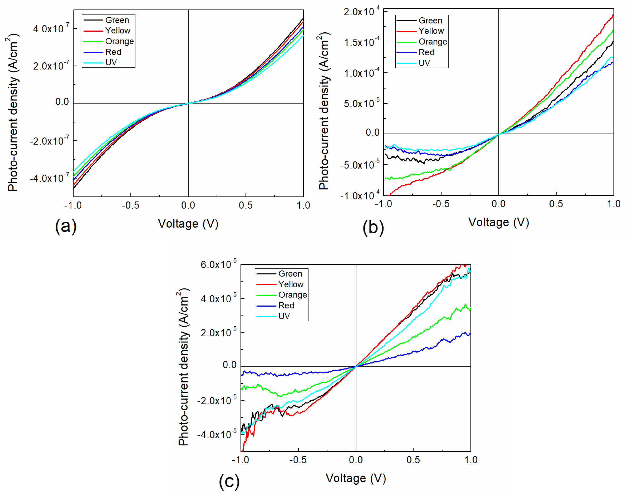
| Sample | Conductivity | Jsc | Photo-Current Density @ 0 V | Ideality Factor | Io |
|---|---|---|---|---|---|
| S/cm | A/cm2 | A/cm2 | n | A | |
| I-CoPc darkness | 2.54 × 10⁻⁷ | 2.41 × 10⁻⁷ | 1.35 × 10⁻⁷ | 2.26 | 3.90 × 10⁻⁶ |
| I-ZnPc darkness | 2.02 × 10⁻⁷ | 1.59 × 10⁻⁵ | 2.33 × 10⁻⁶ | 2.37 | 1.28 × 10⁻⁵ |
| I-CuPc darkness | 6.17 × 10⁻⁸ | 1.26 × 10⁻⁶ | 5.09 × 10⁻⁶ | 2.20 | 1.79 × 10⁻⁶ |
| I-CoPc illuminated | 3.00 × 10⁻⁷ | 3.76 × 10⁻⁷ | 2.25 | 4.59 × 10⁻⁶ | |
| I-ZnPc illuminated | 2.25 × 10⁻⁷ | 1.83 × 10⁻⁵ | 2.33 | 1.34 × 10⁻⁵ | |
| I-CuPc illuminated | 1.44 × 10⁻⁷ | 6.36 × 10⁻⁶ | 2.14 | 4.01 × 10⁻⁶ |
Publisher’s Note: MDPI stays neutral with regard to jurisdictional claims in published maps and institutional affiliations. |
© 2022 by the authors. Licensee MDPI, Basel, Switzerland. This article is an open access article distributed under the terms and conditions of the Creative Commons Attribution (CC BY) license (https://creativecommons.org/licenses/by/4.0/).
Share and Cite
Hamui, L.; Sánchez-Vergara, M.E.; Calatayud-Valdespino, B.; Salcedo, R. Iodine Doping Implementation Effect on the Electrical Response in Metallophthalocyanines (M = Cu, Co, Zn), for Electronic and Photovoltaic Applications. Crystals 2022, 12, 1037. https://doi.org/10.3390/cryst12081037
Hamui L, Sánchez-Vergara ME, Calatayud-Valdespino B, Salcedo R. Iodine Doping Implementation Effect on the Electrical Response in Metallophthalocyanines (M = Cu, Co, Zn), for Electronic and Photovoltaic Applications. Crystals. 2022; 12(8):1037. https://doi.org/10.3390/cryst12081037
Chicago/Turabian StyleHamui, Leon, Maria Elena Sánchez-Vergara, Betsabé Calatayud-Valdespino, and Roberto Salcedo. 2022. "Iodine Doping Implementation Effect on the Electrical Response in Metallophthalocyanines (M = Cu, Co, Zn), for Electronic and Photovoltaic Applications" Crystals 12, no. 8: 1037. https://doi.org/10.3390/cryst12081037