Article

Numerical Simulation of Droplet Filling Mode on Molten Pool and Keyhole during Double-Sided Laser Beam Welding of T-Joints

1
International Joint Laboratory of High-Efficiency Special Green Welding, Material College, North China University of Water Resources and Electric Power, Zhengzhou 450045, China
2
School of Mechanical and Electrical Engineering, Jinhua Polytechnic, Jinhua 321017, China
3
Key Laboratory of Crop Harvesting Equipment Technology of Zhejiang Province, Jinhua 321017, China
4
School of Materials Science and Engineering, Dalian Jiaotong University, Dalian 116028, China
*
Authors to whom correspondence should be addressed.
Crystals 2022, 12(9), 1268; https://doi.org/10.3390/cryst12091268
Submission received: 3 August 2022 / Revised: 30 August 2022 / Accepted: 2 September 2022 / Published: 6 September 2022
(This article belongs to the Special Issue Laser Melting of Metals and Metal Matrix Composites)

Abstract

:
The effects of droplets filling the molten pools during the double-sided laser beam welding (DSLBW) of T-joints was established. The dynamic behavior of the keyhole and the molten pool under different droplet filling modes were analyzed. The results indicated that compared with the contact transition, the stability of metal flow on the keyhole wall was reduced by free transition and slight contact transition. At the later stage of the droplet entering the molten pool via free transition, slight contact transition, and contact transition, the maximum flow velocity of the keyhole wall was 5.33 m/s, 4.57 m/s, and 2.99 m/s, respectively. When the filling mode was free transition or slight contact transition, the keyhole collapsed at the later stage of the droplet entering the molten pool. However, when the filling mode was contact transition, the middle-upper part of the interconnected keyholes became thinner at the later stage of the droplet entering the molten pool. At the later stage of the droplet entering the molten pool via free transition, the flow vortex at the bottom of the keyhole disappeared and the melt at the bottom of the keyhole flowed to the rear of the molten pool, however, the vortex remained during slight contact transition and contact transition.

1. Introduction

In aircraft manufacturing, riveting was used to join fuselage panels [1]. However, the riveting process increased the weight of the fuselage structure and reduced the production efficiency. Laser welding was an advanced connection technology [2,3,4]. Laser welding had concentrated heat input to the welded workpiece, narrow heat affected zone, low welding stress, and small welding deformation. Compared with riveting technology, double-sided laser beam welding (DSLBW) technology had a lighter structure quality and higher work efficiency. German Airbus applied laser welding technology to replace traditional riveting technology in the production of fuselage panel structures [5,6,7]. Oliveira et al. [8] and Enz et al. [9] found that synchronous welding could obtain completely symmetrical weld formations and small welding deformations. At present, DSLBW technology has been applied in the manufacturing of Airbus A340 and A350, and other types of aircraft.
Many researchers mainly analyzed the influence of welding process parameters on the microstructure and properties during DSLBW of T-joints. Han et al. [10], Zhao et al. [11], Badini et al. [12] studied the effects of wire composition, welding speed, and heat treatment on the microstructure and properties of welds during DSLBW of T-joints, respectively.
Porosity defect was one of the main welding defects during DSLBW of aluminum alloy T-joints. Although welding parameters could affect porosity defects, the fluctuation of keyholes was the main cause of welding bubbles, and the flow of the molten pool determined whether welding bubbles could escape from the molten pool [13,14]. In order to improve the mechanical properties of the weld, filler wire must be added for DSLBW of T-joints. However, in the current literature on the numerical simulation of DSLBW of T-joints, filler metal was prefabricated on both sides of T-joints before welding, so the influence of welding wire on the weld pool was not considered. Yang et al. [15,16,17] established the numerical model of DSLBW of T-joints. Assuming that the workpiece surface was a rigid surface, the relationship between the interconnectivity of two laser beams and the porosity of weld was studied. Chen et al. [18] found that the oscillations of the keyhole profile continuously existed in the process of DSLBW of T-joints, before and after the keyhole coupling.
Relevant literature revealed that the stability of the keyhole and the molten pool was greatly affected by the filler wire during plate welding [19,20,21,22]. Up to now, no literature has been reported on the dynamic behavior of the droplet filling into the molten pool during DSLBW process of T-joints.
In this paper, the impact of droplets filling the molten pool during double-sided laser beam welding (DSLBW) of T-joints was established by. The dynamic behavior of the keyhole and the molten pool under different droplet filling modes were analyzed.

2. Mathematical Modeling

In this research work, the FLUENT 19.0 software was adopted to investigate the effect of the droplet filling mode on the molten pool and keyhole during DSLBW of T-joints. The laser power was 1800 W, the droplet filling speed was 2.7 m/min, the droplet radius was 0.6 mm, and the welding speed was 3.8 m/min. The influence of the welding driving forces was considered in the mathematical model. The main driven forces of the weld pool can be obtained from the literature [23].

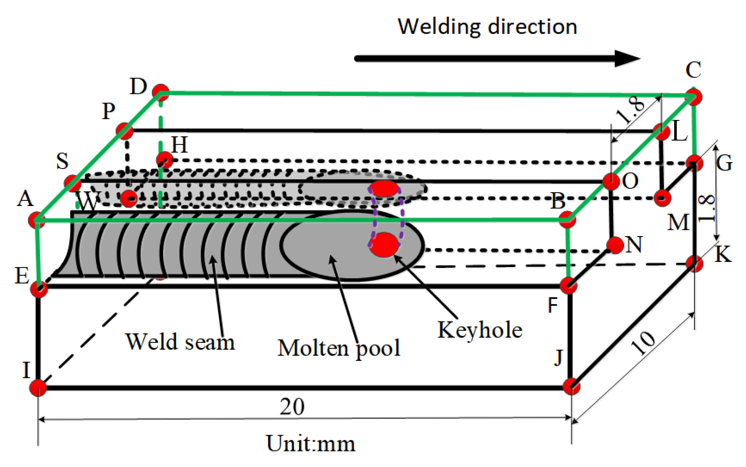
2.1. Numerical Model

The calculation region of the droplet filling into the molten pool was established during DSLBW of T-joints, as shown in Figure 1.
The welding workpiece was constantly melted under the action of the laser heat source. The keyhole wall was a gas-liquid interface, and there were continuous dynamic changes of the liquid phase and gas phase at the keyhole boundary. In this paper, the volume of fluid (VOF) method was used to deal with the problem of gas-liquid conversion on the keyhole wall [24]. The normal vector n and the curvature κ of the free surface could be calculated as follows:
n = F | F |
κ = n
To reduce the workload of the computer, the melting process of welding wire was not considered. It was assumed that the front end of the filler wire was melted and entered the molten pool in the form of a liquid droplet.

2.2. Heat Source Model

The rotary Gaussian heat source model was written as follows [25]:
q l a s e r = 9 α a b s Q π R 0 2 H ( 1 e 3 ) exp [ 9 ( x 2 + y 2 ) R 0 2 log ( H / z ) ]
where Q and H represent the heat source energy and the heat source height, respectively; R0 is the effective radius of the laser beam.

2.3. Mathematical Model of Droplet Filling

The thermal interaction after the liquid droplet fell into the molten pool was treated as the change of the periodic enthalpy of melt in the molten pool. The heat formula of the droplet was expressed as [26]:
Q a = ρ π r w 2 w f H d
where w f is the droplet velocity; ρ is droplet density; r w is the droplet radius.
The effective heat formula of the droplet entering the molten pool was expressed as [26]:
Q d = ρ π r w 2 w f C p l ( T d T l )
where T d is the liquid droplet temperature; C p l is specific heat of liquid droplet; T l is the liquidus temperature of liquid droplet.
According to the fixed grid numerical calculation method [27], the double-focus laser welding process of T-joints in a Cartesian coordinate system should satisfy the following equations [28]:
Mass conservation equation:
( ρ ) t + ( ρ u ) x + ( ρ v ) y + ( ρ w ) z + S m = 0
Energy conservation equation:
( ρ H ) t + ( ρ u H ) x + ( ρ v H ) y + ( ρ w H ) z = x ( k T x ) + y ( k T y ) + y z ( k T z ) + S H
Momentum conservation equation:
( ρ u ) t + ( ρ u u ) x + ( ρ u v ) y + ( ρ u w ) z = x ( u u x ) + y ( u u y ) + z ( u u z ) P x + S x
( ρ v ) t + ( ρ u v ) x + ( ρ v v ) y + ( ρ v w ) z = x ( u v x ) + y ( u v y ) + z ( u v z ) P y + S y
( ρ w ) t + ( ρ u w ) x + ( ρ v w ) y + ( ρ w w ) z = x ( u w x ) + y ( u w y ) + z ( u w z ) P z + S z
where u, v, and w are velocity components; H, k and µ are the enthalpy, thermal conductivity, and viscosity, respectively; Sm, Sx, Sy, Sz and SH are the source terms of the governing equation.
The thermophysical parameters of 6056 aluminum alloy are described in [29] (Table 1).
C p ( J k g 1 K 1 ) = { 0.001 × T 2 + 1.1609 × T + 267.71 300 < T 573 0.0009 × T 2 0.3901 × T + 514.45 573 < T 913 0.0009 × T 2 + 0.5832 × T + 435.14 913 < T 2740
k ( W m 1 K 1 ) = { 0.0001 × T 2 0.0697 × T + 95.334 300 < T 860 0.0048 × T 2 + 9.2812 × T 4275.6 860 < T 917 0.00001 × T 2 + 0.0582 × T + 148.74 917 < T 2740
μ ( kg m 1 K 1 ) = { 1 × 10 7 × T 2 0.0002 × T + 0.1202 897 < T 937 2 × 10 11 × T 2 5 × 10 7 × T + 0.0038 937 < T 2650 6 × 10 8 × T 2 + 0.0003 × T 0.4151 2650 < T 2720
where Cp, k, and μ are specific heat, thermal conductivity and dynamic viscosity, respectively.

3. Results and Discussion

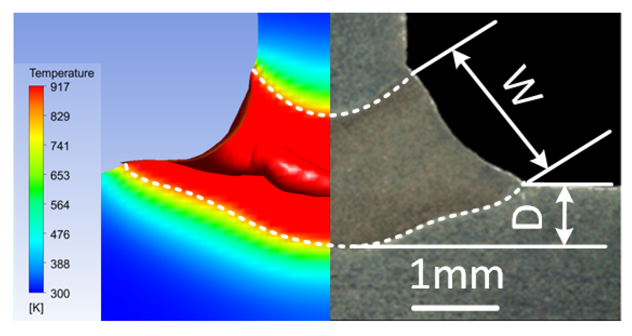
3.1. Numerical Model Validation

Figure 2 shows the comparison of the weld profiles obtained by experiment and numerical simulation during DSLBW of T-joints.
The experimentally determined weld cross sections were compared with the corresponding calculated geometries as shown in Figure 2. In the experimental results, the W was about 1.9 mm and the D was 0.8 mm. It was found that the weld profiles were in agreement between the experiment and numerical simulation.

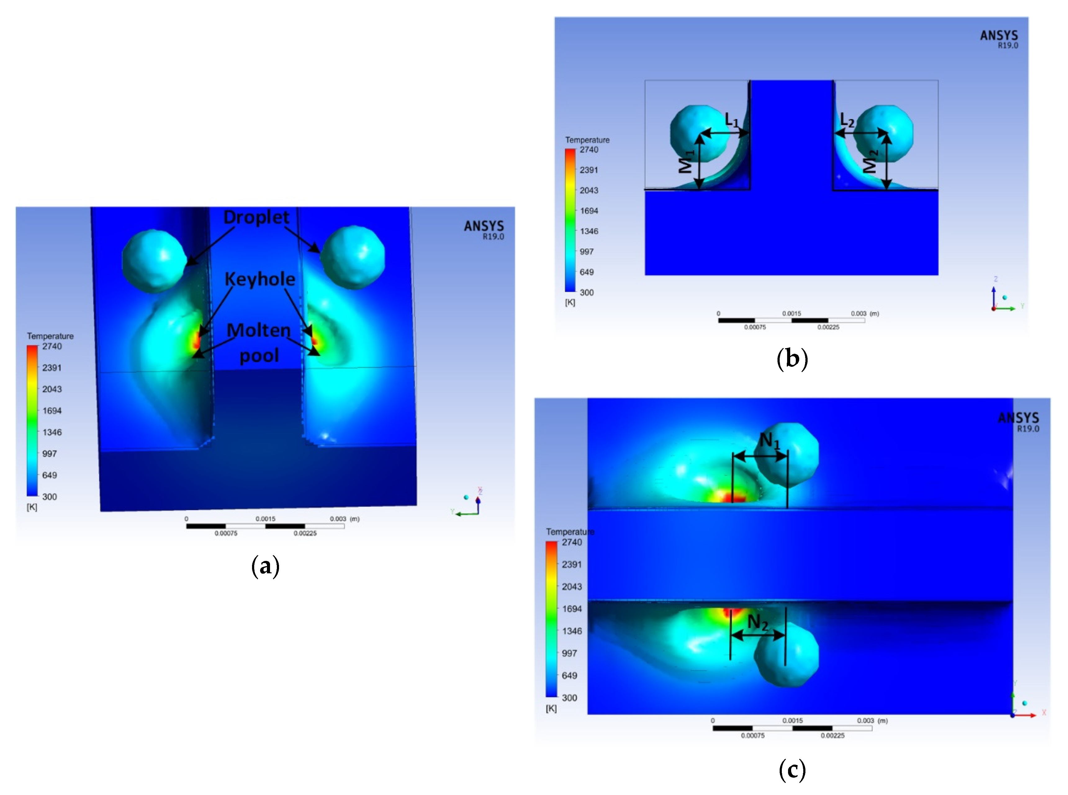
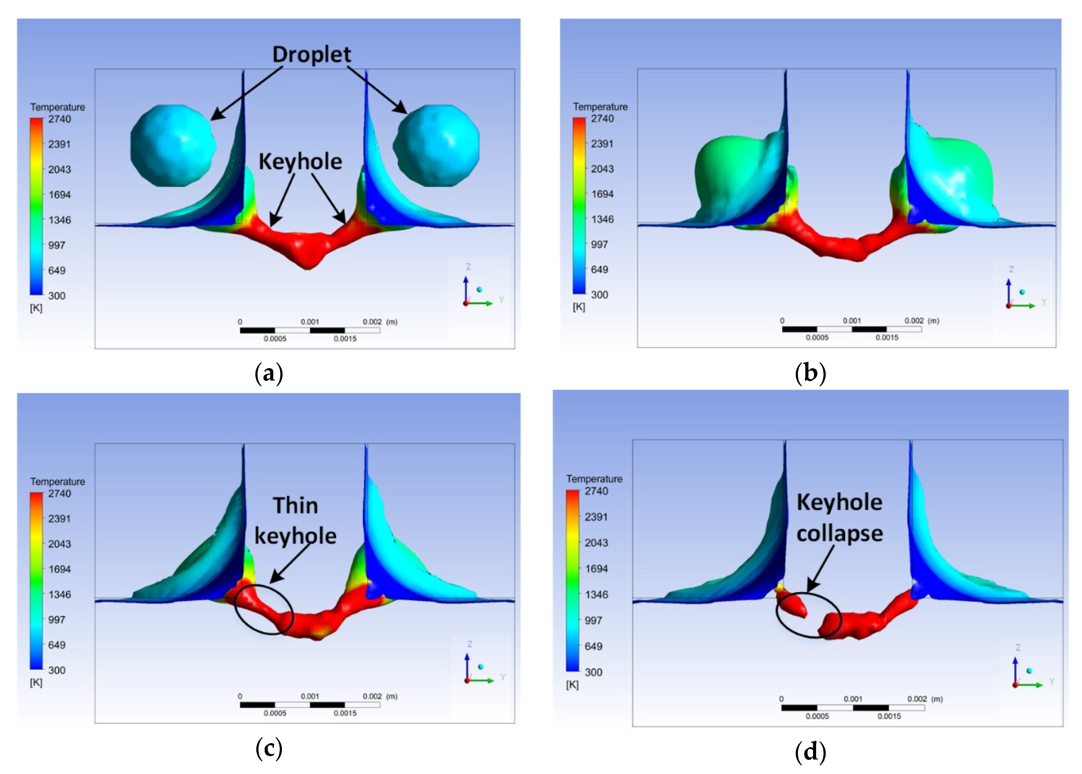
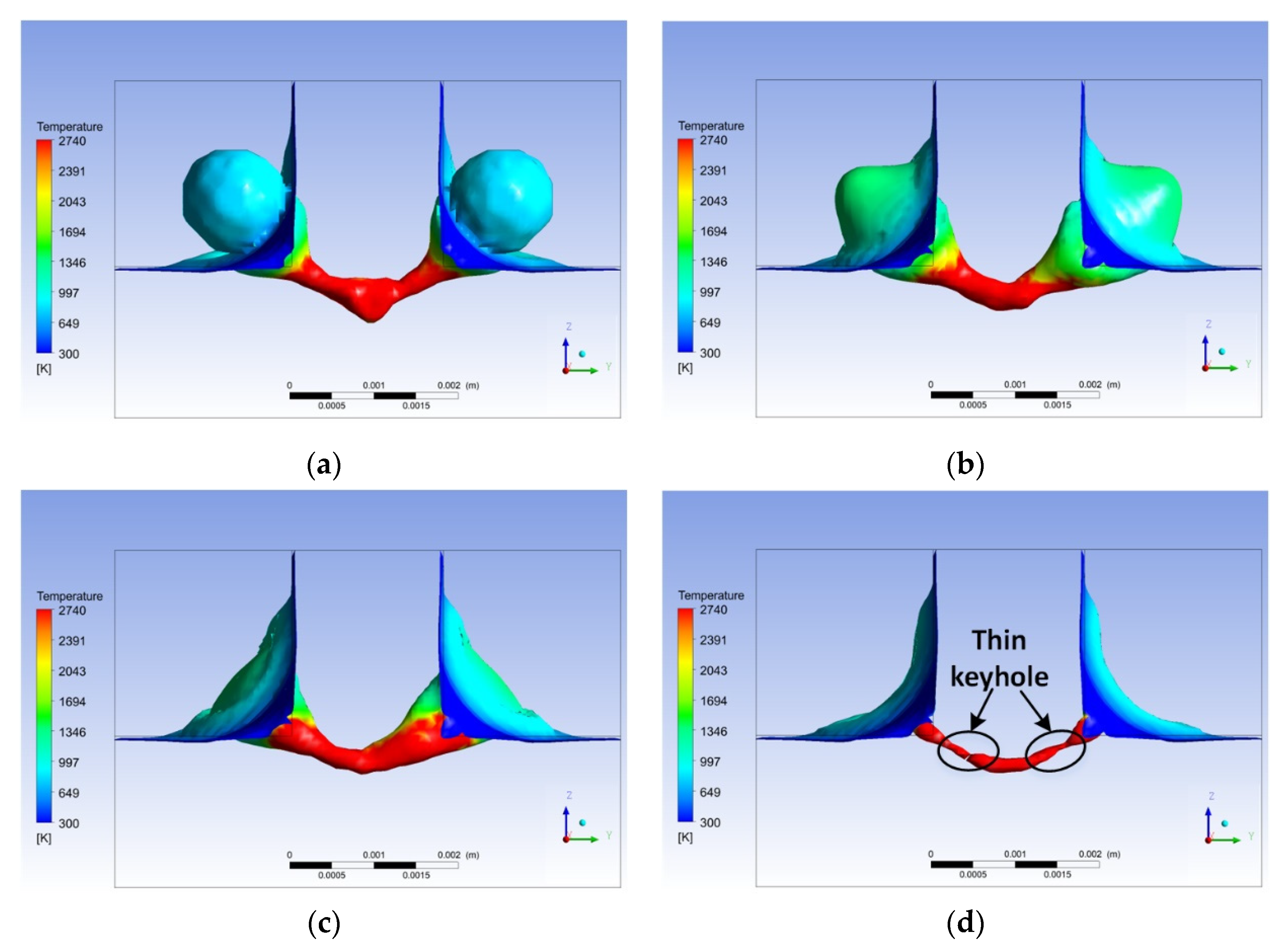
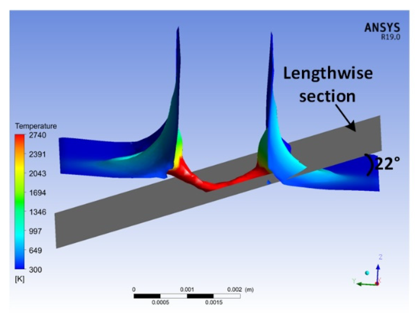
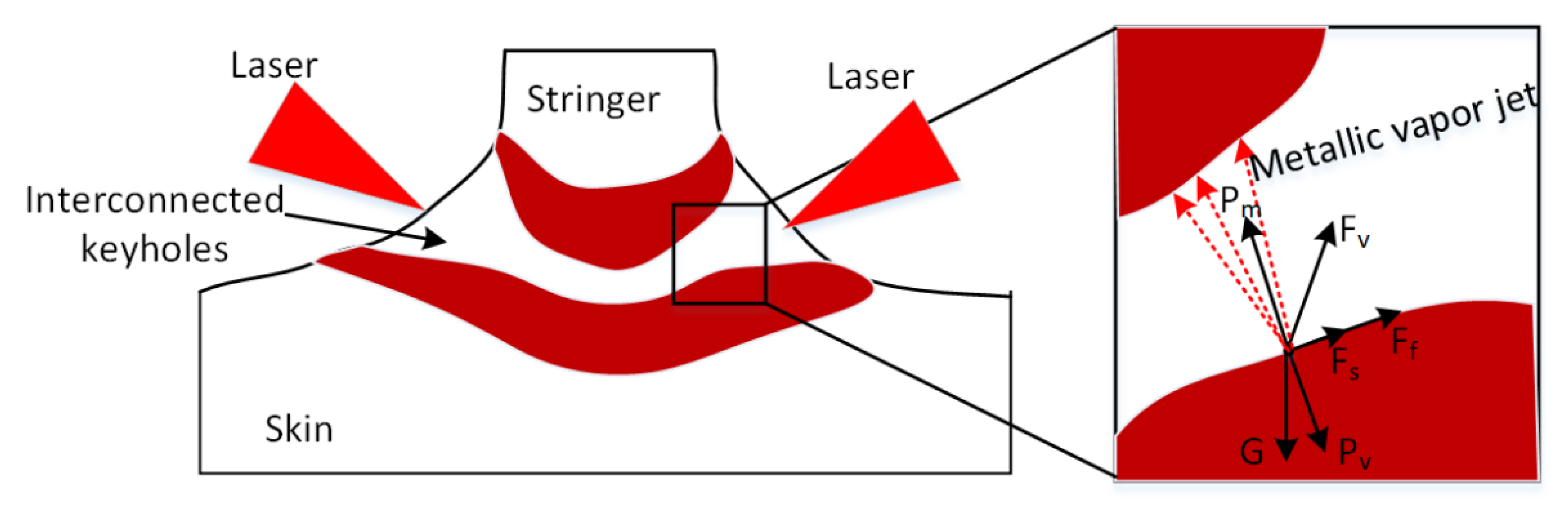
3.2. Dynamic Behavior of the Keyhole

The 3D simulation model of droplet filling position during DSLBW of T-joints is presented in Figure 3. L represents the distance between the stringer and the center of the droplet. M represents the distance between the skin and the center of the droplet. N represents the distance between the center of the keyhole and the center of the droplet. In this paper, N1 = 1 mm, N2 = 1 mm.
Figure 4 shows the three-dimensional morphology of the droplet filling mode during DSLBW of T-joints. As shown in Figure 4a, L1 = L2 = 1.0 mm, M1 = M2 = 1.1 mm, and the droplet filling mode was a free transition. As shown in Figure 4b, L1 = L2 = 0.8 mm, M1 = M2 = 0.9 mm, and the droplet filling mode was a slight contact transition. As shown in Figure 4c, L1 = L2 = 0.7 mm, M1 = M2 = 0.8 mm, and the droplet filling mode was a contact transition.
Figure 5, Figure 6 and Figure 7 show the three-dimensional transient behavior of the keyhole with droplet filling modes of free transition, slight contact transition, and contact transition, respectively.
The different transition methods of the droplet entering the molten pool affected the stability of the keyhole in different ways. The free and slight contact transition filling modes had a greater impact on the keyhole than contact transition; the middle-upper part of the interconnected keyholes became thinner, as shown in Figure 5c and Figure 6c. At the later stage of the droplet entering the molten pool, the keyhole collapsed at the position where the keyhole became thinner, as shown in Figure 5d and Figure 6d. However, during contact transition, at the later stage of the droplet entering the molten pool, the middle-upper part of the interconnected keyholes became thinner but did not collapse, as shown in Figure 7d. The droplet impacted the keyhole after entering the molten pool, affected the stability of the keyhole, and even caused the collapse of the interconnected keyholes. After the keyhole collapsed, the generated bubbles did not escape from the molten pool before the solidification of the molten pool, resulting in porosity defects in the weld. At present, the relevant literature only studied the reason for the high porosity of DSLBW of T-joints from the perspective of the molten pool flow field, without considering the influence of the dynamic fluctuation of the keyhole under droplet filling on weld porosity defects [30].
Figure 8, Figure 9 and Figure 10 show the three-dimensional flow fields of the keyhole with droplet filling modes of free transition, slight contact transition, and contact transition, respectively. As shown in Figure 8, Figure 9 and Figure 10, the flow direction at the opening of the keyhole was from the center of the keyhole to the outside of the keyhole, which was mainly caused by the Marangoni-driven flow [31,32,33]. The melt flow direction of the droplet entering the molten pool was opposite to the flow direction at the opening of the keyhole, which affected the melt flow velocity and the stability of the keyhole wall. At the later stage of the droplet entering the molten pool, the maximum flow velocity of the keyhole wall was 5.33 m/s, 4.57 m/s, and 2.99 m/s, when the droplets entered via free, slight contact, and contact transitions, respectively. This also shows that compared with contact transition, the free transition and slight contact transition filling modes reduced the stability of the keyhole.

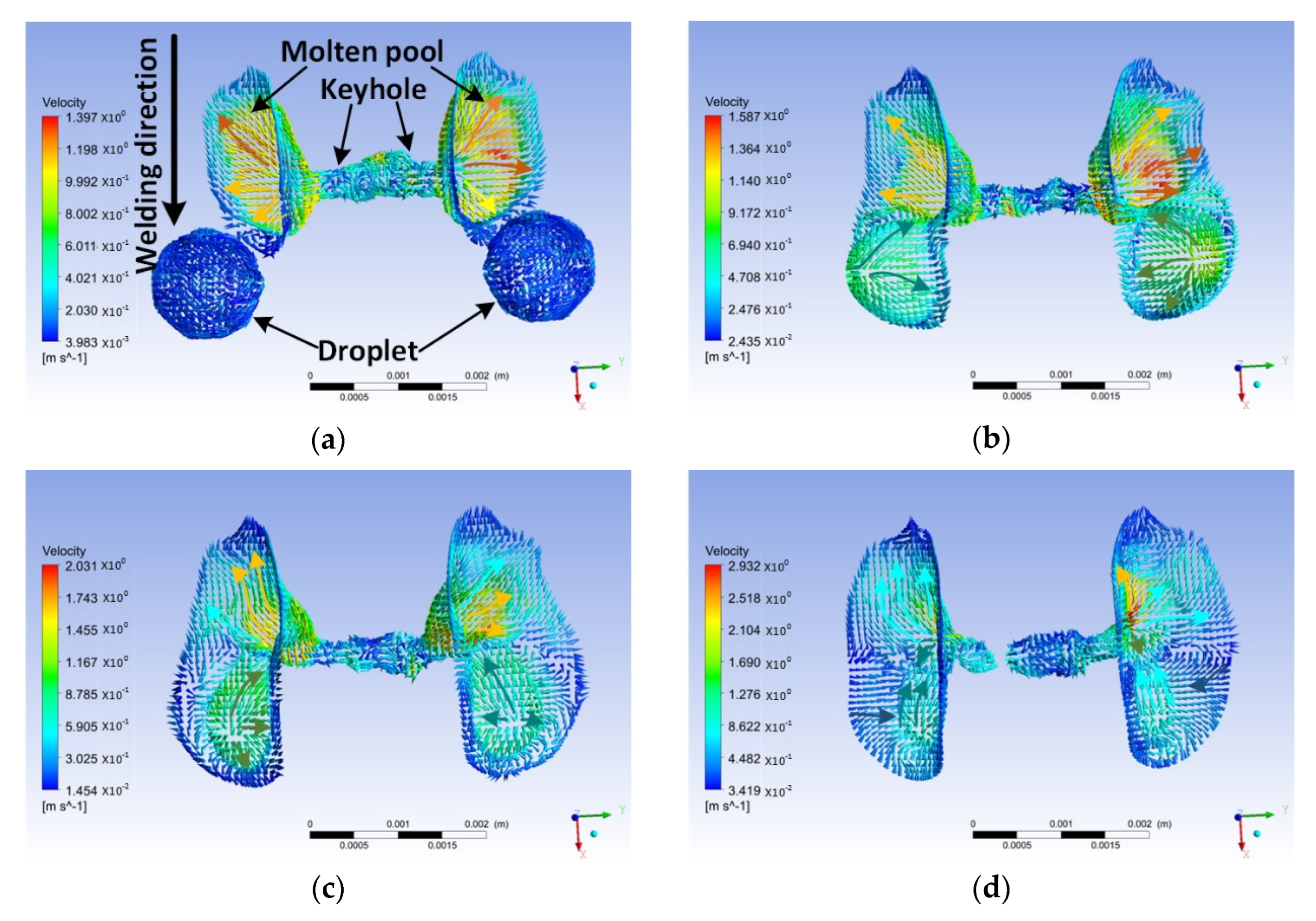
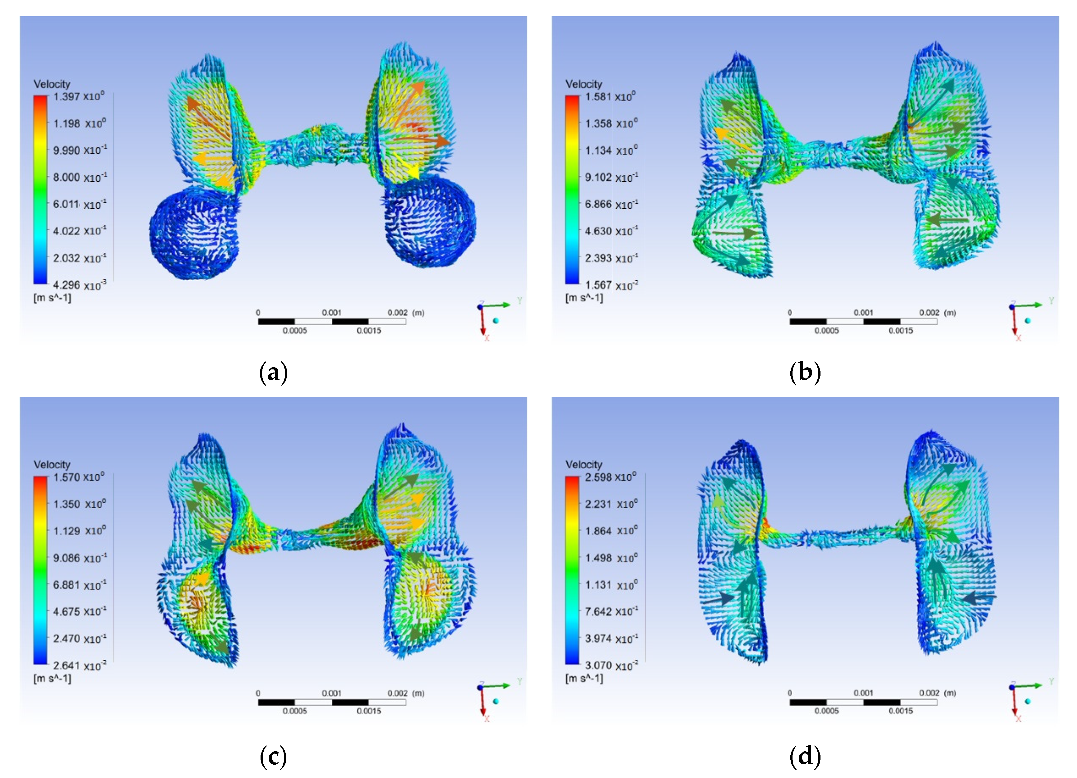
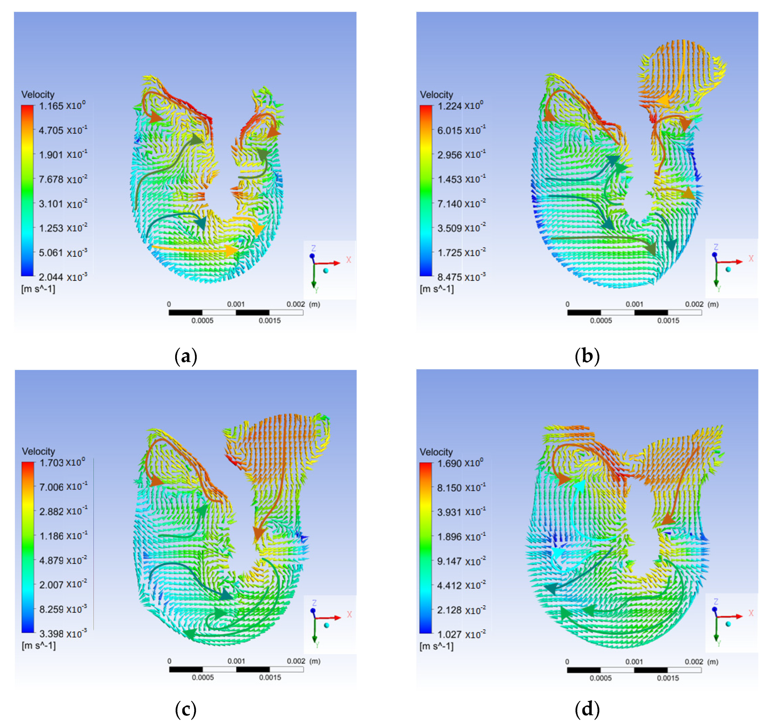
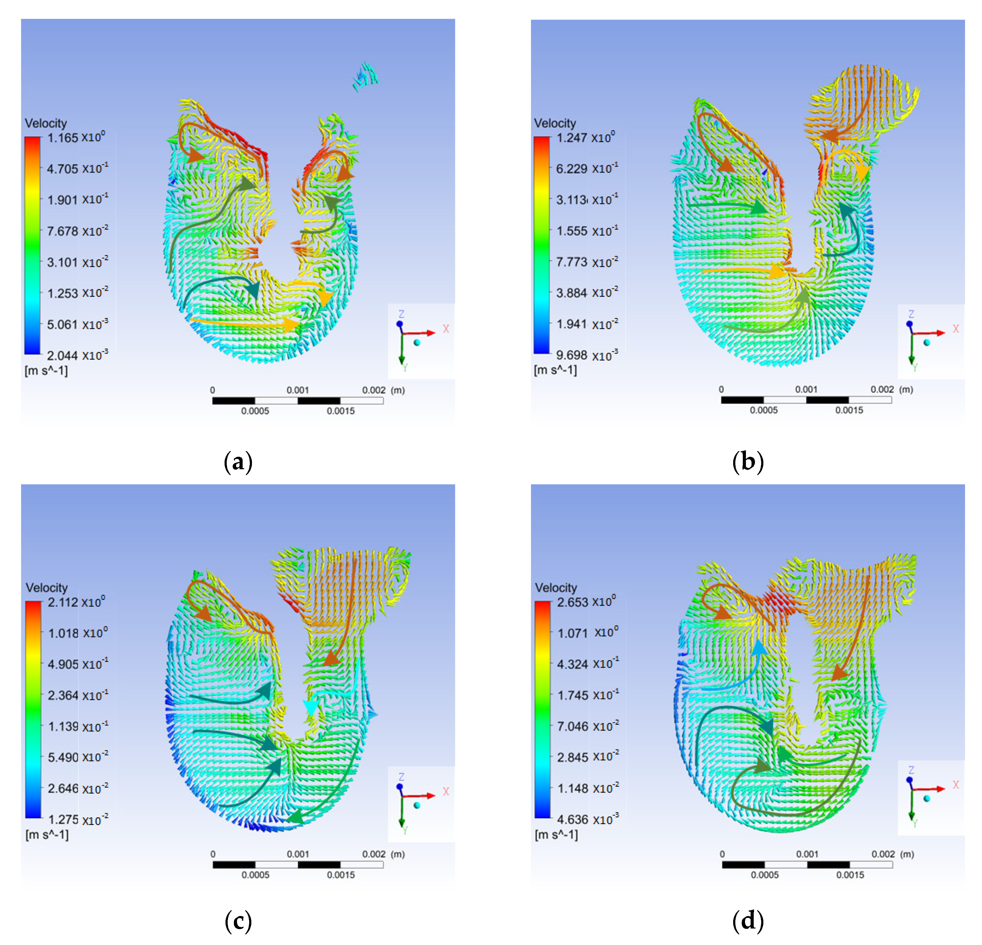
3.3. Melt Flow of the Molten Pool

Figure 11 shows the intercept position of the longitudinal section flow field during the DSLBW process for T-joints. The gray surface was a section, as shown in Figure 11.
Figure 12 shows the longitudinal section flow field during the DSLBW process for T-joints with the droplet transition in the form of free transition, slight contact transition, and contact transition, respectively.
When a droplet enters the molten pool, it affects the flow field of the molten pool. In the early stage of the droplet entering the molten pool, the melt at the bottom of the keyhole flowed from the rear to the front of the molten pool, as shown in Figure 12a,b, Figure 13a,b and Figure 14a,b. At the later stage of the droplet entering the molten pool, the melt flowed from the front to the rear of the molten pool, as shown in Figure 12d, Figure 13d and Figure 14d.
At the early stage of the droplet entering the molten pool, the flow vortex caused by the Marangoni-driven flow appeared in the front and the rear of the keyhole opening in the longitudinal section of the molten pool, as shown in Figure 12a,b, Figure 13a,b and Figure 14a,b. At the later stage of the droplet entering the molten pool, the flow vortex caused by the Ma-rangoni-driven flow disappeared in front of the keyhole opening in the longitudinal sec-tion of the molten pool, as shown in Figure 12d, Figure 13d and Figure 14d.
At the later stage of the droplet entering the molten pool via free transition, the flow vortex at the bottom of the keyhole disappeared, and the melt at the bottom of the keyhole flowed to the rear of the molten pool. When the droplet filling mode was a slight contact transition or contact transition, the vortex at the bottom of the keyhole remained.
Table 2 shows the schematic representation of the flow field in the longitudinal section of the molten pool when the droplets entered the molten pool via the three different filling modes.
The pressure on the keyhole wall during the DSLBW process for T-joints is shown in Figure 15. The pressures acting on the wall of the keyhole included friction force (Ff), hydrostatic pressure (Pm), recoil pressure (Pv), surface tension (Fs), and hydrodynamic pressure (Fv). In the process of the DSLBW, the keyhole was relatively stable when it was in dynamic equilibrium. By using a high-speed camera, Tao et al. [34] studied the influence of the welding wire on the weld pool during the DSLBW process for T-joints. They found that the mode by which the filler wire entered the molten pool after melting had an effect on the weld porosity. When the front end of the filler wire was melted and the liquid metal entered the molten pool via contact transition, the porosity of the weld was low. In our paper, during the later stage of the droplet entering the molten pool via contact transition, the middle-upper part of the interconnected keyholes became thinner but did not collapse. When the keyhole was less prone to collapse, the weld porosity was lower. However, when the droplet entered the molten pool via free transition or slight contact transition, the keyhole collapsed at the later stage. This was because free transition and slight contact transition had a greater impact on the front wall of the keyhole than contact transition. Furthermore, the uniformity of the laser energy density distribution in the keyhole irradiated by the laser beam was affected, which in turn further affected the evaporation of metal elements in the keyhole. In the area irradiated by the laser beam, the vapor recoil force of metal vaporization increased. In the area that could not be irradiated by the laser beam, the vapor recoil force of the metal vaporization would be reduced, which would further cause severe fluctuation of the keyhole.

4. Conclusions

When droplets entered the molten pool via free transition or slight contact transition, the stability of metal flow on the keyhole wall was reduced. At the later stage of the droplet entering the molten pool, the maximum flow velocity of the keyhole wall was 5.33 m/s, 4.57 m/s and 2.99 m/s for free transition, slight contact transition, and contact transition, respectively.
The keyhole collapsed at the later stage of the droplet entering the molten pool via free transition or slight contact transition. However, when the droplet entered via contact transition, the middle-upper part of the interconnected keyholes became thinner but did not collapse.
When a droplet enters the molten pool, it affects the flow field of the molten pool. We found that the melt at the bottom of the keyhole flowed from the rear to the front of the molten pool in the early stage of a droplet entering the molten pool, and that the reverse occurred in the later stage.
A greater impact on the longitudinal section flow field of the molten pool was observed during free transition of droplets into the molten pool. At the later stage, the flow vortex at the bottom of the keyhole disappeared, and the keyhole flowed to the rear of the molten pool. The vortex remained during contact and slight contact transition of the droplets into the molten pool.

Author Contributions

Conceptualization, J.P. and X.Y.; methodology, J.P.; software, J.P.; validation, J.P., Z.Y.; formal analysis, J.P., X.W. and J.L.; investigation, J.P., P.H. and J.L.; resources, J.P.; data curation, J.P.; writing—original draft preparation, J.P.; writing—review and editing, J.P.; visualization, J.P., S.L. and Z.Y.; supervision, J.P., X.Y. and J.G.; project administration, J.P.; funding acquisition, J.P. and X.Y. All authors have read and agreed to the published version of the manuscript.

Funding

This research was supported by the National Natural Science Foundation of China (52071165) the National Natural Science Foundation of China (51771083) the Henan Province Key R & D and Promotion Project (Science and Technology Research) (222102220082), Henan Postdoctoral Research Project (202003076), the Henan Excellent Youth Fund Project (202300410268), the Scientific and technological innovation talents in Colleges and universities in Henan Province (22HASTIT026), Special support for high-level talents in Henan Province “Central Plains Talent Program—top young talents in Central Plains” (ZYBJ202126).

Institutional Review Board Statement

Not applicable.

Informed Consent Statement

Not applicable.

Data Availability Statement

Not applicable.

Conflicts of Interest

The authors declare no conflict of interest.

References

  1. Chen, S.; Zhan, X.; Zhao, Y.; Wu, Y.; Liu, D. Influence of laser power on grain size and tensile strength of 5a90 al–li alloy t-joint fabricated by dual laser-beam bilateral synchronous welding. Met. Mater. Int. 2019, 27, 1671–1685. [Google Scholar] [CrossRef]
  2. Tan, C.; Su, J.; Liu, Y.; Feng, Z.; Song, X.; Wang, X.; Chen, B.; Xia, H. Enhanced interfacial bonding strength of laser bonded titanium alloy/cfrtp joint via hydrogen bonds interaction. Compos. Part B Eng. 2022, 239, 109966. [Google Scholar] [CrossRef]
  3. Wang, Y.; Jiang, P.; Zhao, J.; Geng, S.; Xu, B. Effects of energy density attenuation on the stability of keyhole and molten pool during deep penetration laser welding process: A combined numerical and experimental study. Int. J. Heat Mass Transf. 2021, 176, 121410. [Google Scholar] [CrossRef]
  4. Ai, Y.; Jiang, P.; Wang, C.; Mi, G.; Geng, S. Experimental and numerical analysis of molten pool and keyhole profile during high-power deep-penetration laser welding. Int. J. Heat Mass Transf. 2018, 126, 779–789. [Google Scholar] [CrossRef]
  5. Janasekaran, S.; Jamaludin, M.F.; Muhamad, M.R.; Yusof, F.; Abdul Shukor, M.H. Autogenous double-sided t-joint welding on aluminum alloys using low power fiber laser. Int. J. Adv. Manuf. Technol. 2016, 90, 3497–3505. [Google Scholar] [CrossRef]
  6. Sun, X.; Shehab, E.; Mehnen, J. Knowledge modelling for laser beam welding in the aircraft industry. Int. J. Adv. Manuf. Technol. 2012, 66, 763–774. [Google Scholar] [CrossRef]
  7. Dittrich, D.; Standfuss, J.; Liebscher, J.; Brenner, B.; Beyer, E. Laser beam welding of hard to weld al alloys for a regional aircraft fuselage design—first results. Phys. Procedia 2011, 12, 113–122. [Google Scholar] [CrossRef]
  8. Oliveira, A.C.; Siqueira, R.H.M.; Riva, R.; Lima, M.S.F. One-sided laser beam welding of autogenous t-joints for 6013-t4 aluminium alloy. Mater. Des. 2015, 65, 726–736. [Google Scholar] [CrossRef]
  9. Enz, J.; Khomenko, V.; Riekehr, S.; Ventzke, V.; Huber, N.; Kashaev, N. Single-sided laser beam welding of a dissimilar aa2024–aa7050 t-joint. Mater. Des. 2015, 76, 110–116. [Google Scholar] [CrossRef]
  10. Han, B.; Tao, W.; Chen, Y.; Li, H. Double-sided laser beam welded t-joints for aluminum-lithium alloy aircraft fuselage panels: Effects of filler elements on microstructure and mechanical properties. Opt. Laser Technol. 2017, 93, 99–108. [Google Scholar] [CrossRef]
  11. Zhao, Y.; Zhan, X.; Chen, S.; Bai, M.; Gong, X. Study on the shear performance and fracture mechanism of t-joints for 2219 aluminum alloy by dual laser-beam bilateral synchronous welding. J. Alloys Compd. 2020, 847, 156511. [Google Scholar] [CrossRef]
  12. Badini, C.; Pavese, M.; Fino, P.; Biamino, S. Laser beam welding of dissimilar aluminium alloys of 2000 and 7000 series: Effect of post-welding thermal treatments on t joint strength. Sci. Technol. Weld. Join. 2013, 14, 484–492. [Google Scholar] [CrossRef]
  13. Zou, J.L.; Wu, S.K.; He, Y.; Yang, W.X.; Xu, J.J.; Xiao, R.S. Distinct morphology of keyhole wall during high power fibre laser deep penetration welding. Sci. Technol. Weld. Join. 2015, 20, 655–658. [Google Scholar] [CrossRef]
  14. Kawahito, Y.; Mizutani, M.; Katayama, S. High quality welding of stainless steel with 10 kw high power fibre laser. Sci. Technol. Weld. Join. 2009, 14, 288–294. [Google Scholar] [CrossRef]
  15. Yang, Z.; Zhao, X.; Tao, W.; Jin, C. Effects of keyhole status on melt flow and flow-induced porosity formation during double-sided laser welding of aa6056/aa6156 aluminium alloy t-joint. Opt. Laser Technol. 2019, 109, 39–48. [Google Scholar] [CrossRef]
  16. Yang, Z.; Tao, W.; Li, L.; Chen, Y.; Shi, C. Numerical simulation of heat transfer and fluid flow during double-sided laser beam welding of t-joints for aluminum aircraft fuselage panels. Opt. Laser Technol. 2017, 91, 120–129. [Google Scholar] [CrossRef]
  17. Yang, Z.; Tao, W.; Zhao, X.; Chen, Y.; Shi, C. Numerical modelling and experimental verification of thermal characteristics and their correlations with mechanical properties of double-sided laser welded t-joint. Int. J. Adv. Manuf. Technol. 2017, 92, 1609–1618. [Google Scholar] [CrossRef]
  18. Chen, S.; Zhao, Y.; Tian, S.; Gu, Y.; Zhan, X. Study on keyhole coupling and melt flow dynamic behaviors simulation of 2219 aluminum alloy t-joint during the dual laser beam bilateral synchronous welding. J. Manuf. Processes 2020, 60, 200–212. [Google Scholar] [CrossRef]
  19. Yu, Y.; Wang, C.; Hu, X.; Wang, J.; Yu, S. Porosity in fiber laser formation of 5a06 aluminum alloy. J. Mech. Sci. Technol. 2010, 24, 1077–1082. [Google Scholar] [CrossRef]
  20. Salminen, A.; Kujanpaa, V. Effect of wire feed position on laser welding with filler wire. J. Laser Appl. 2003, 15, 2–10. [Google Scholar] [CrossRef]
  21. Ohnishi, T.; Kawahito, Y.; Mizutani, M.; Katayama, S. Butt welding of thick, high strength steel plate with a high power laser and hot wire to improve tolerance to gap variance and control weld metal oxygen content. Sci. Technol. Weld. Join. 2013, 18, 314–322. [Google Scholar] [CrossRef]
  22. Salminen, A.; Kujanpaa, V.; Moisio, T. Interactions between laser beam and filler metal. Weld. J. 1996, 75, 9s–13s. [Google Scholar]
  23. Peng, J.; Li, L.; Lin, S.; Zhang, F.; Pan, Q.; Katayama, S. High-speed x-ray transmission and numerical study of melt flows inside the molten pool during laser welding of aluminum alloy. Math. Probl. Eng. 2016, 2016, 1409872. [Google Scholar] [CrossRef]
  24. Hirt, C.; Nichols, B. Volume of fluid (VOF) method for the dynamics of free boundaries. J. Comput. Phys. 1981, 39, 201–225. [Google Scholar] [CrossRef]
  25. Li, X.; Lu, F.; Cui, H.; Tang, X.; Wu, Y. Numerical modeling on the formation process of keyhole-induced porosity for laser welding steel with t-joint. Int. J. Adv. Manuf. Technol. 2014, 72, 241–254. [Google Scholar] [CrossRef]
  26. Mishra, S.; Chakraborty, S.; DebRoy, T. Probing liquation cracking and solidification through modeling of momentum, heat, and solute transport during welding of aluminum alloys. J. Appl. Phys. 2005, 97, 094912. [Google Scholar] [CrossRef]
  27. Voller, V.; Swaminathan, C. General source-based method for solidification phase change. Numer. Heat Transf. Part B Fundam. 1991, 19, 175–189. [Google Scholar] [CrossRef]
  28. Zhao, H.; Niu, W.; Zhang, B.; Lei, Y.; Kodama, M.; Ishide, T. Modelling of keyhole dynamics and porosity formation considering the adaptive keyhole shape and three-phase coupling during deep-penetration laser welding. J. Phys. D Appl. Phys. 2011, 44, 485302. [Google Scholar] [CrossRef]
  29. Peng, J.; Xu, H.; Yang, X.; Wang, X.; Li, S.; Long, W.; Zhang, J. Numerical simulation of molten pool dynamics in laser deep penetration welding of aluminum alloys. Crystals 2022, 12, 873. [Google Scholar] [CrossRef]
  30. Tao, W.; Yang, Z.; Shi, C.; Dong, D. Simulating effects of welding speed on melt flow and porosity formation during double-sided laser beam welding of aa6056-t4/aa6156-t6 aluminum alloy t-joint. J. Alloys Compd. 2017, 699, 638–647. [Google Scholar] [CrossRef]
  31. Ribic, B.; Tsukamoto, S.; Rai, R.; DebRoy, T. Role of surface-active elements during keyhole-mode laser welding. J. Phys. D Appl. Phys. 2011, 44, 485203. [Google Scholar] [CrossRef]
  32. Wu, C.S.; Zhang, T.; Feng, Y.H. Numerical analysis of the heat and fluid flow in a weld pool with a dynamic keyhole. Int. J. Heat Fluid Flow 2013, 40, 186–197. [Google Scholar] [CrossRef]
  33. Zhang, D.; Wang, M.; Shu, C.; Zhang, Y.; Wu, D.; Ye, Y. Dynamic keyhole behavior and keyhole instability in high power fiber laser welding of stainless steel. Opt. Laser Technol. 2019, 114, 1–9. [Google Scholar] [CrossRef]
  34. Tao, W.; Yang, Z.; Chen, Y.; Li, L.; Jiang, Z.; Zhang, Y. Double-sided fiber laser beam welding process of t-joints for aluminum aircraft fuselage panels: Filler wire melting behavior, process stability, and their effects on porosity defects. Opt. Laser Technol. 2013, 52, 1–9. [Google Scholar] [CrossRef]
Figure 1. The calculation region of DSLBW of T-joints.
Crystals 12 01268 g001
Figure 2. Comparison of the weld profiles obtained by experiment and numerical simulation during DSLBW of T-joints.
Crystals 12 01268 g002
Figure 3. The 3D simulation model of droplet filling position during DSLBW of T-joints: (a) the 3D simulation model, (b) the front view of Figure 3a, (c) the vertical view of Figure 3a.
Crystals 12 01268 g003
Figure 4. Three-dimensional morphology of the droplet filling mode during DSLBW of T-joints: (a) droplet filling mode: free transition, (b) droplet filling mode: slight contact transition, (c) droplet filling mode: contact transition.
Crystals 12 01268 g004
Figure 5. The keyhole shape with free transition of the droplet during DSLBW of T-joints: (a) t = 12.0 ms, (b) t = 15.2 ms, (c) t = 15.8 ms, (d) t = 16.2 ms.
Crystals 12 01268 g005
Figure 6. The keyhole shape with slight contact transition of the droplet during DSLBW of T-joints: (a) t = 12.0 ms, (b) t = 13.4 ms, (c) t = 14.0 ms, (d) t = 14.2 ms.
Crystals 12 01268 g006
Figure 7. The keyhole shape with contact transition of the droplet during DSLBW of T-joints: (a) t = 12.0 ms, (b) t = 13.2 ms, (c) t = 13.4 ms, (d) t = 13.8 ms.
Crystals 12 01268 g007
Figure 8. Three−dimensional flow field of the keyhole with free transition of the droplet during DSLBW of T-joints: (a) t = 12.0 ms, (b) t = 15.2 ms, (c) t = 15.8 ms, (d) t = 16.2 ms.
Crystals 12 01268 g008
Figure 9. Three−dimensional flow field of the keyhole with slight contact transition of the droplet during DSLBW of T-joints: (a) t = 12.0 ms, (b) t = 13.4 ms, (c) t = 14.0 ms, (d) t = 14.2 ms.
Crystals 12 01268 g009
Figure 10. Three−dimensional flow field of the keyhole with contact transition of the droplet during DSLBW of T-joints: (a) t = 12.0 ms, (b) t = 13.2 ms, (c) t = 13.4 ms, (d) t = 13.8 ms.
Crystals 12 01268 g010
Figure 11. Schematic diagram of the lengthwise section during the DSLBW process for T-joint.
Crystals 12 01268 g011
Figure 12. Variation in melt flow of the lengthwise section with droplet free transition during DSLBW of T-joints: (a) t = 12.0 ms, (b) t = 15.2 ms, (c) t = 15.8 ms, (d) t = 16.2 ms.
Crystals 12 01268 g012
Figure 13. Variation in melt flow of the lengthwise section with droplet slight contact transition during DSLBW of T-joints: (a) t = 12.0 ms, (b) t = 13.4 ms, (c) t = 14.0 ms, (d) t = 14.2 ms.
Crystals 12 01268 g013
Figure 14. Variation in melt flow of the lengthwise section with droplet contact transition during DSLBW of T-joints: (a) t = 12.0 ms, (b) t = 13.2 ms, (c) t = 13.4 ms, (d) t = 13.8 ms.
Crystals 12 01268 g014
Figure 15. Schematic diagram of the pressure on the keyhole wall during the DSLBW process for T-joints.
Crystals 12 01268 g015
Table 1. The thermophysical parameters of 6056 aluminum alloy.
PropertySymbolUnitValue
Solid densityρskg/m−32720
Liquid densityρlkg/m−32590
Solidus temperatureTsK860
Liquidus temperatureTLK917
Boiling temperatureTgK2740
Thermal expansion coefficientβkK−11.92 × 10⁻⁵
Convective heat transfer coefficienth0W/K−1m−215
Surface tensionδ0N/m−10.914
Surface tension gradientAδN/m−1K−1−3.5 × 10−4
Radiation emissivityε---0.08
Ambient temperatureTrefK300
Table 2. Schematic representation of the flow field in the longitudinal section of the molten pool when the droplets entered the molten pool via the three different filling modes.
Filling ModeEarly Stage of Droplet Entering the Molten PoolLater Stage of Droplet Entering Molten Pool
Free transition Crystals 12 01268 i001 Crystals 12 01268 i002
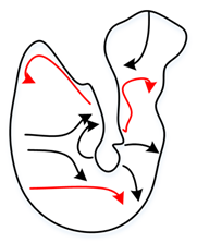
Slight contact transition
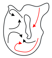
 Crystals 12 01268 i003 Crystals 12 01268 i004
Contact transition Crystals 12 01268 i005 Crystals 12 01268 i006
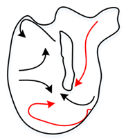
Publisher’s Note: MDPI stays neutral with regard to jurisdictional claims in published maps and institutional affiliations.

