Article

Numerical Studies of Batch and Inline High Shear Melt Conditioning Technology Using Different Rotors

by
Gerard Serge Bruno Lebon
*,
Jayesh B. Patel
and
Zhongyun Fan
Brunel Centre for Advanced Solidification Technology (BCAST), Brunel University London, Uxbridge UB8 3PH, UK
*
Author to whom correspondence should be addressed.
Crystals 2022, 12(9), 1299; https://doi.org/10.3390/cryst12091299
Submission received: 18 August 2022 / Revised: 12 September 2022 / Accepted: 13 September 2022 / Published: 14 September 2022
(This article belongs to the Special Issue Phase Transition in External Fields)

Abstract

:
When casting aluminum alloy billets, high shear melt conditioning (HSMC) technology refines the resulting grain size, reduces the number of defects, and improves mechanical properties without the need to add polluting and expensive chemical grain refiners. These resultant improvements spring from the high shear rates that develop in the rotor–stator gap and the stator holes facing the leading edge of the rotor. Despite the growing literature on rotor–stator mixing, it is unclear how the different rotor–stator parameters affect the performance of high shear treatment. To upscale this technology and apply it to processes that involve large melt volumes, an understanding of the performance of the rotor–stator design is crucial. In this paper, we present the results of computational fluid dynamics (CFD) studies of high shear melt conditioning in continuous and batch modes with different rotor designs. These studies build upon our earlier work by studying the effect of rotor variation in a stator design consisting of rows of small apertures at different rotor speeds spanning from 1000 to 10,000 revolutions per minute. While no clear-cut linear pattern emerges for the rotor performance (as a function of the design parameters), the rotor geometry is found to affect the distributive mixing of microparticles, but it is insignificant with regards to their disintegration.

1. Introduction

Because light weighing reduces CO2 emissions and increases fuel efficiency, this practice is important for the automotive and aerospace industries. These industries therefore use light alloys (based on aluminum and magnesium), which can provide both high strength and light weight [1]. However, they also need cast billets with the fewest possible defects and a homogenous composition. During the casting of these light alloys, inclusions, such as gas (bubbles) and oxides, conventionally worsen the melt quality and, in turn, that of the resulting cast [2].
Various technologies are used to treat the melt, refine the as-cast microstructure, and reduce the defects in the cast billet, thereby improving the mechanical properties and increasing the performance of the resulting components. Treatment methods using external fields include ultrasonic melt treatment using a sonotrode [3,4], which has been proven on the industrial scale to be effective for degassing, filtration, and grain refinement of light ally melts [5]. More recent research exploits the resonance frequencies of containing vessels for contactless acoustic treatment using a top electromagnetic coil, paving the way for the treatment of reactive melts, such as titanium [6,7].
High shear melt conditioning technology [8,9] proposes an efficient melt alternative by using “harmful” oxides and other inclusions to strengthen the resulting cast upon treatment [10,11,12]. Intensive mixing deagglomerates the metallic inclusions and redistributes them throughout the melt, thereby reducing the defects in the resulting cast [13,14]. Melt conditioning also modifies the flow pattern in the sump of direct-chill (DC) casting with the increased heat transfer and temperature homogenization around the rotor–stator mixer resulting in finer, equiaxed grains [13,15]. These beneficial effects and the concomitant improvement of thermomechanical properties all occur without chemical inoculation, thereby increasing the recyclability of the cast or wrought alloy. A successful application of HSMC is the deironing of highly contaminated aluminum alloy melts, where intensive shearing reduces the sedimentation time and leads to faster iron removal [16,17,18].
The mechanism behind high shear melt conditioning is deceivingly simple: a high-speed rotor rotates at speeds of ~1000–10,000 RPM inside a stator. The rapid revolutions of the rotor blades entrain fluid into the stator volume and, due to fluid continuity, eject this entrained fluid back into the liquid bulk. Deagglomeration of solid inclusions occurs within the rotor–stator clearance—the small gap between the rotor and the stator—and the large velocity gradients developing on the stator hole walls that face the leading edges of the rotor [19]. The power number of batch rotor–stator mixers is independent of the Reynolds number in the turbulent flow regime that is of interest for HSMC [20]. Despite this operational simplicity, the flow pattern around mixers is complicated, and a universal scaling law for mixers still eludes researchers [21].
Numerical modeling has been extensively used in the literature to understand and assess the operation of rotor–stator devices [22,23]. Numerical studies of the stator geometry have determined that a larger fraction of energy dissipation occurs in smaller stator openings compared with larger ones [24,25]. Stator geometries that maximize the volume of the pseudo-cavern have also been studied [26]. The authors’ earlier numerical study specifically assessed the efficacy of the different stator designs that are used in high shear melt conditioning [25] in batch mode. This stator study followed earlier CFD work on the pseudo-cavern in melt conditioning using Reynolds-Averaged Navier–Stokes (RANS) turbulence models [27]. The study revealed that the degradation in shearing performance upon changing the operation of mixers with small stator holes from batch to continuous mode is less severe than that occurring when enlarging the stator holes.
In this study, the influence of the rotor geometry on the flow pattern, turbulence dissipation, shear rate, volume flow rate, and power draw are analyzed. The mixers run in batch mode—in a closed bottom cylinder—and in continuous (or inline) mode—with melt flowing through the cylindrical domain at an average speed of 0.1 m s−1, corresponding to a ‘bulk’ Reynolds number of 8000. The stator geometry is fixed and corresponds to the 42 mm diameter stator (Mixer A) from an earlier study [25]; the mixer head consists of four rows, each with 18 small round holes of a diameter of 2.5 mm each. The predicted fields are discussed, and their implication for rotor design is outlined in the following sections.

2. Method

2.1. Numerical Method

The open-source computational fluid dynamics (CFD) software library OpenFOAM 7 [28] was used to solve the continuity and momentum conservation equations using the finite volume method. The 2003 version of the k–ω shear stress transport (SST) model [29] was used to provide turbulence closure:
k t + u k = D k k + G 2 3 k u β * ω k + S k      
ω t + u ω = D ω ω + γ G ν 2 3 γ ω u β ω ω 2 F 1 1 C D k ω + S ω  
where k is the turbulent kinetic energy; ω is the dissipation rate, and the default model coefficients are retained [29].
An implicit Euler first-order differencing scheme was used for time discretization. Convective terms were treated with the second-order linear-upwind scheme. The selected implementation of the pressure–velocity coupling was the PIMPLE algorithm, which is a combination of the PISO [30] and SIMPLE [31] algorithms, with the SIMPLE algorithm being used within every time step and the iterations being outer corrections. For numerical stability, an adaptive time step was used, where a maximum Courant number of 1.0 was enforced. An additional constraint on the time step size was the imposition of a maximum of a 1 degree turn of the rotor; this restriction was required as the more liberal condition of 1/30th of the rotation time reported elsewhere [23] led to a divergence in the numerical solution. These restrictions resulted in a maximum time step of 0.32 ms in the case of 1000 RPM. Each simulation was run for a minimum of 65 full revolutions of the rotor mesh zone before the results could be analyzed, as the flow was fully developed by then.

2.2. Geometry

This paper assesses the performance of the three rotor designs that are shown in Figure 1. All rotors are of a height of 21 mm and a diameter of 30 mm. Rotor A consists of four blades of a width of 7 mm. Rotor B consists of two blades of a width of 7 mm. Rotor C has a petal design made from cutting four cylinders of a diameter of 10 mm from a larger cylinder of a diameter of 30 mm. Rotors A and C were chosen for this CFD study as they are available for future water validation experiments in our laboratory. Rotor B is the first design of a planned parametric study assessing the effect of the number of blades on shearing performance.
The rotor–stator mixer was immersed in a cylindrical pipe of diameter 80 mm filled with fluid. The boundary conditions are listed in Table 1. Only the inlet boundary conditions differ between the batch and inline cases. For the batch case, the prescribed velocity at the inlet was 0 m s−1, identical to a wall no-slip boundary. For the inline mode, an inbound flow of 0.1 m s−1 normal to the inlet surface was prescribed. Standard outflow conditions (zero normal gradient for velocity and fixed pressure value) were imposed at the outlet. The mesh density was fine enough at the walls to employ the selected turbulence models. The liquid properties were set to those of water with a density of ρ = 1000 kg m−2 and a kinematic viscosity of ν = 1.0 × 10 6 m2 s−1. Turbulence was prescribed using an estimate of the turbulence intensity and a mixing length obtained from the wetted diameter of the pipe.
The liquid properties were set to those of water, as water is a good physical analogue to aluminum [32,33] and the flow can be readily visualized in experiments. The cases were run with a rotor speed of 1000 RPM. The unstructured meshes were generated with the finite element mesher SALOME 9.4 [34]. The sliding mesh method [35] was used to implement the rotation of the rotor mesh volume.

3. Results and Discussion

3.1. Mesh Independence

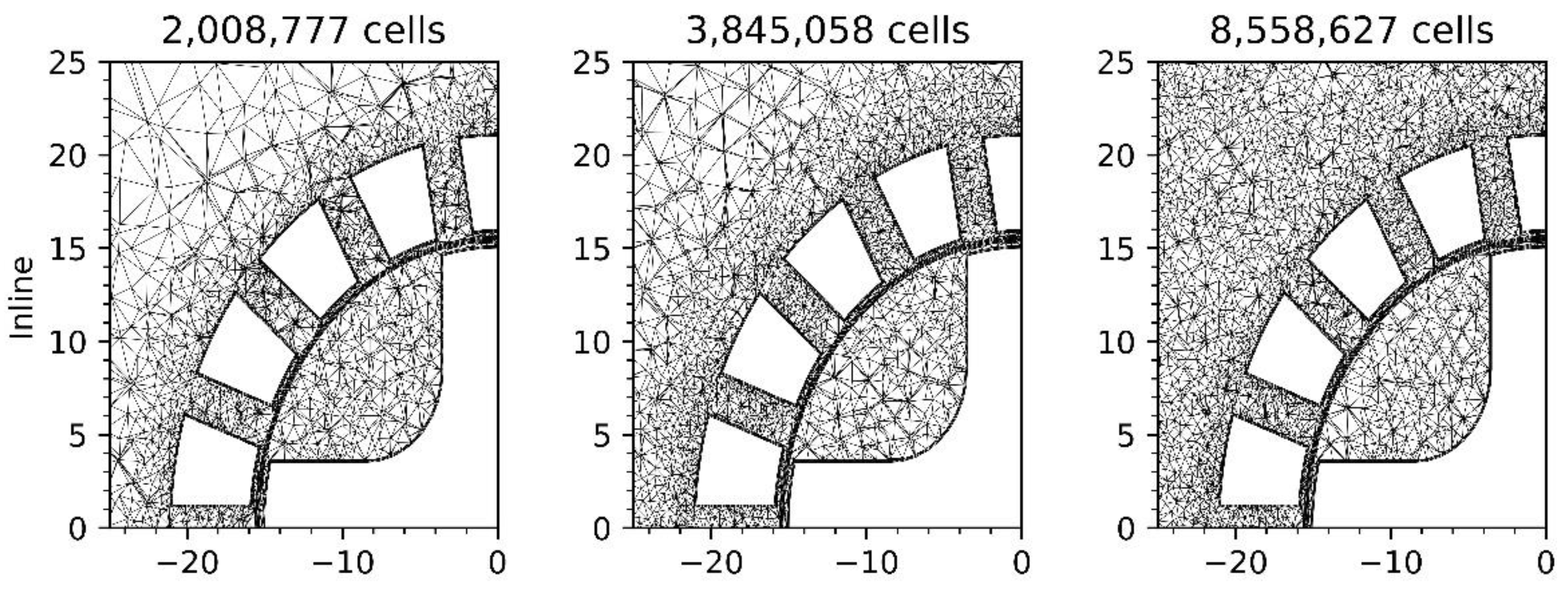
According to a previous RANS study from Utomo et al. [23], doubling the grid size from 500,000 to 1 million cells (together with time step refinement from 1/30 to 1/60 rotor revolution time) does not significantly improve the flowrate and time-averaged jet radial velocity predictions for a 25 mm mixer. This claim has been used as justification in subsequent CFD studies of rotor–stator designs using the same RANS model (the k-ε model) [24,36]. This effect was investigated in this study using the k-ω SST model in the present cases using the meshes shown in Figure 2. As shown in Table 2, the predicted power number does not deviate significantly across the studied grid sizes. Therefore, meshes of a few million cells are considered as converged for this study.

3.2. Validation with Experimental Data

The methodology that was used in this paper was validated by comparing its predictions with the measured power number of Padron [37] for an L4RT square head mixer with 4 blade rotors and 4 alternate stator holes rows, each having 23 holes. In this validation study, the rotor speed was 4000 RPM, and the rotor diameter D was 28.2 mm. The operating fluid was water. The power number P o was calculated using [38]
P o = P ρ N 3 D 5 ,  
where the power P that is required to maintain the rotor rotation was calculated as
P = 2 π N T ,  
where T is the torque on the total rotor surface, and N is the rotor speed in revolutions per second. The results were also compared with other CFD simulations using the k- ε model [24] and an LES model [36], for which the water mass flow rate through the mixer was also available. The results are presented in Table 3. The power number and the mass flow rates are in good agreement with the other CFD studies from the literature. The predicted power number is also in very good agreement with the experimental work of Padron [37]. These results therefore validate the numerical approach followed in this manuscript.

3.3. Flow Field

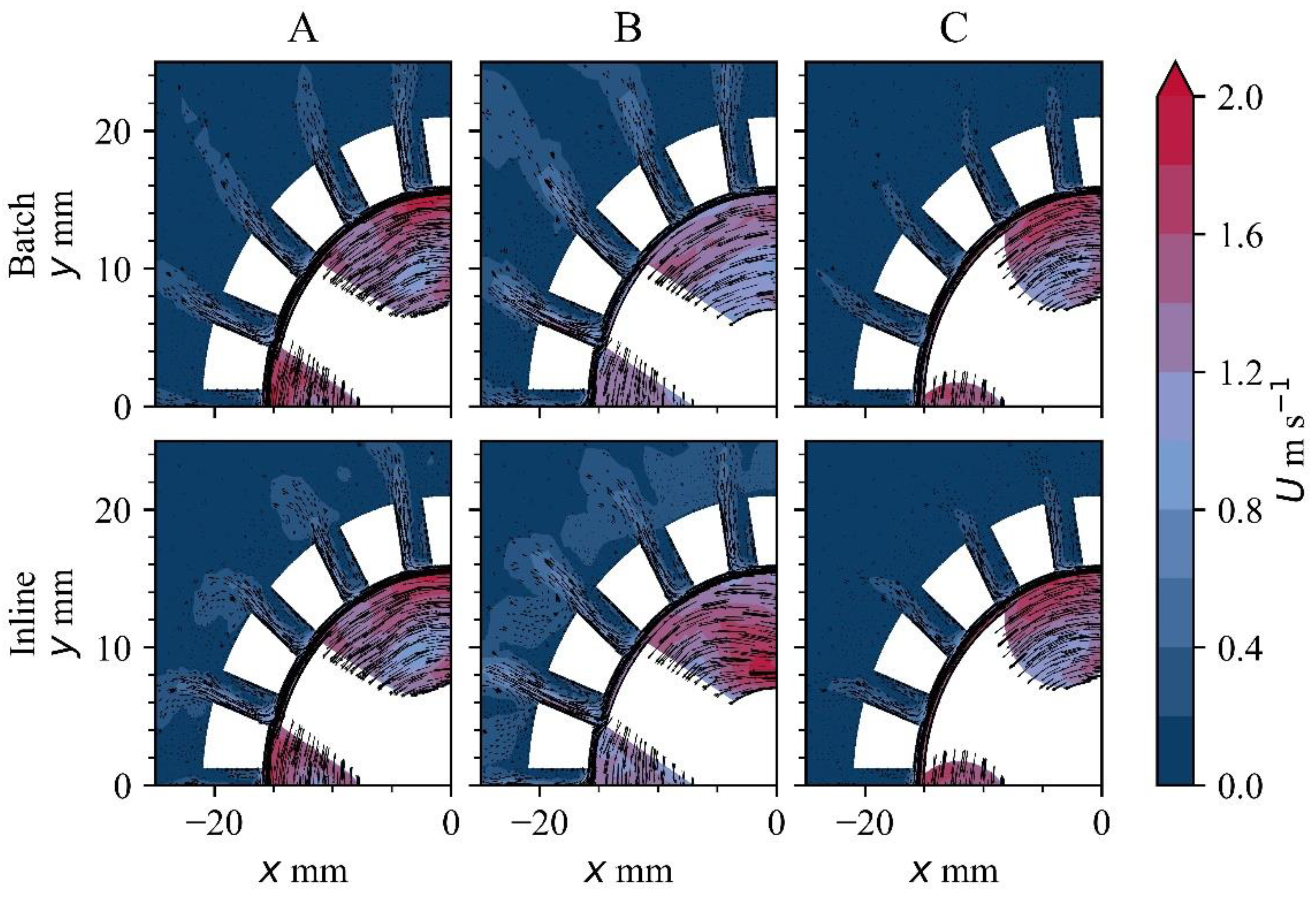
Figure 3 shows instantaneous snapshots of the flow field around the mixers after 65 full rotor revolutions. Figure 4 shows a closer view of the rotor–stator region and the pseudo-cavern for each case. The velocity magnitude contours are colored using the same scale. The flow gradient is similar for rotor designs A and C, with the largest velocity gradients confined to the volume within the stator cup in both cases. However, rotor design B with fewer blades shows the largest difference with a large flow gradient developing inside the empty area within the stator cup. The fluid is also forced out at a higher speed outside the mixer with rotor designs A and B; however, for design C, the exit jets were almost indiscernible in this contour scale. This could be a consequence of the large outer surface area of each rotor blade overlapping three stator holes at a time.
While strong jets are desirable for enhanced mixing, they can result in a larger recirculation zone below the mixer as shown in Figure 5; this is disadvantageous for DC casting as the large rotary flow along the mould axis leads to the emergence of a segregation ring at the center of a cast billet [15]. In this case, a design such as rotor C would be preferable provided it provides an acceptable shear rate.

3.4. Turbulence Kinetic Viscosity

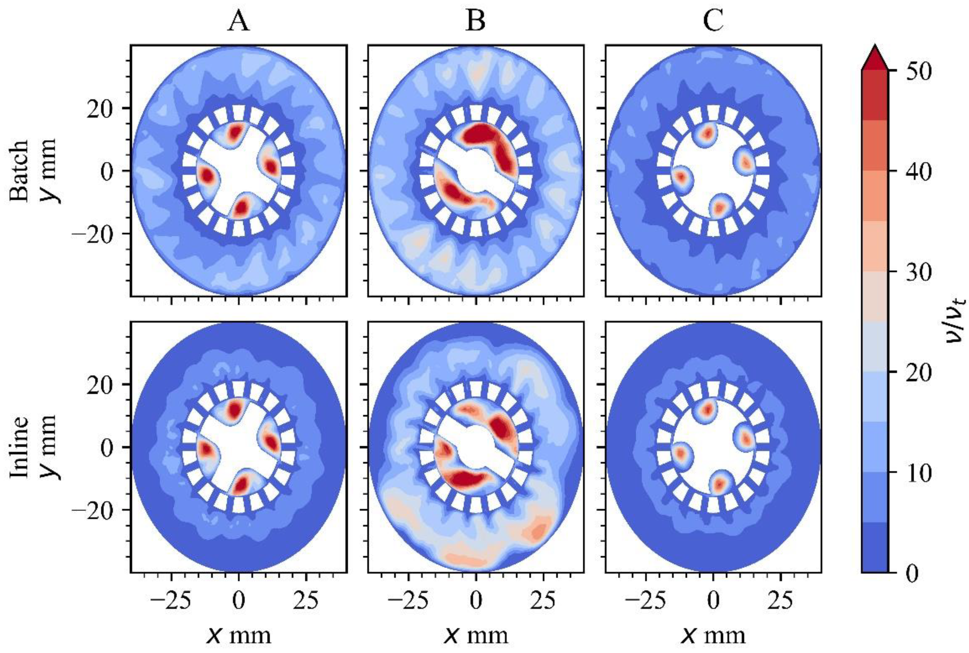
Figure 6 shows the corresponding kinetic turbulent viscosity ratio for each case. This ratio was obtained by dividing the kinetic turbulent viscosity field by the laminar viscosity of the fluid and shows where distributive mixing is expected to occur. Two main observations arise from these contours: (a) As in the previous mixer design study [25], the overall mixing effect is not severely degraded by operating the mixer in inline mode as the turbulent viscosity values between both operating modes are comparable; this shows that a continuous melt treatment of slow-moving melt is possible, and the melt conditioning technology can readily be transferred to launders or conduits of melt following the tundish. (b) The effect of the rotor choice is more consequential on the mixing performance that any degradation that would arise by switching melt conditioning from a batch treatment mode to a continuous treatment mode.

3.5. Strain Rate

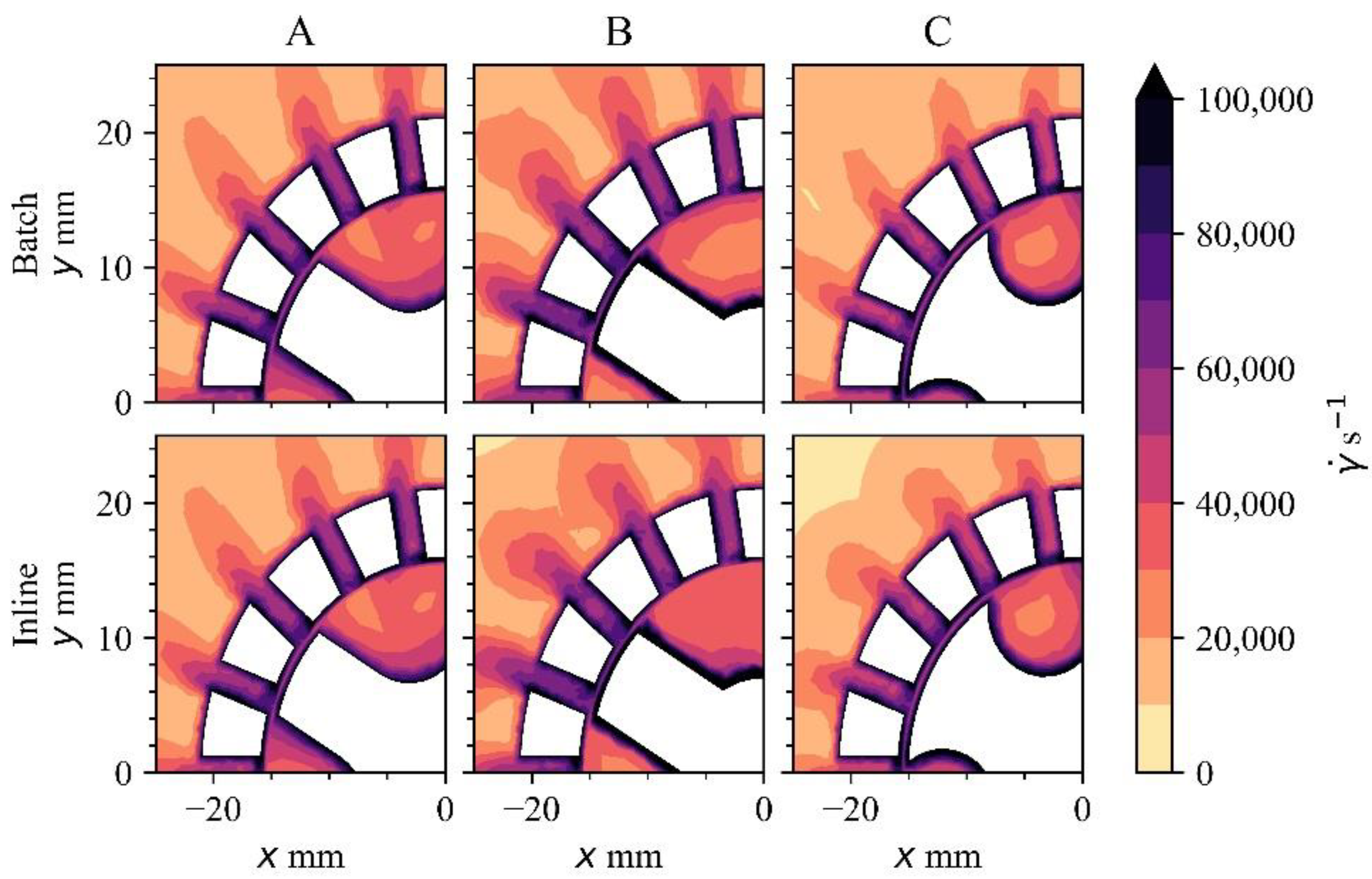
Figure 7 shows the shear rate contours. In all six cases, the shear rates offer the same deagglomeration performance with shear rates larger than 105 s−1 inside the rotor–stator clearance and the stator holes, an observation consistent with earlier findings [27]. This prediction is interesting because it surmises that the rotor design is inconsequential for the deagglomeration of solid inclusions. It is therefore possible to use a rotor design that is easier to clean, thereby increasing the portability of the rotor–stator mixer unit along different processes in a casting plant. Since rotor C does not result in a large rotary flow under the mixer, it can potentially be used in DC casting where HSMC will still disintegrate particle agglomerations while attenuating any segregation band in the center of the billet.

3.6. Volume Flow Rate

Table 4 shows a comparison of the predicted volume flow rates through each rotor–stator mixer, given a different rotor design. The volume flow (pumping) rate through the mixer was affected by the rotor design, with rotor C forcing less melt through the stator holes. This can be attributed to the smaller interblade volume in this rotor design. The melt flow rate was not severely degraded by switching from a batch treatment mode to an inline mode, with the melt flow rates for each design within a standard deviation of each other for rotors A and B and three standard deviations for rotor C.

3.7. Power Number

The predicted power number for each rotor design is shown in Table 5. Rotor B, having the largest power draw (the working fluid, mixer diameter, and rotor speed being the same in all cases) to shear the melt is less effective; i.e., it will require more power to provide the same disintegration rate (shown in Figure 7) as the other designs. As noted in the volume flow rate section, the power draw of each rotor is not severely affected by switching between batch and inline modes, with only a slightly significant increase when switching to inline treatment.

4. Conclusions

A numerical study of three rotor designs was conducted, and their performance for melt conditioning in batch and continuous modes was assessed. The rotor design occupying the smallest volume in the stator cup showed the largest variation in flow pattern and mixing in the mixer zone. However, this design is not recommended for DC casting as the recirculation that is generated below the mixer will lead to a segregation band in the middle of the billet. The deagglomeration effect was not altered with any rotor design. The choice of the rotor is therefore inconsequential for the disintegration of particles but matters for distributive mixing. This paves the way for the exploration of simpler rotor designs that can be used in bulk high shear melt conditioning.

Author Contributions

Conceptualization, G.S.B.L.; methodology, G.S.B.L.; software, G.S.B.L.; validation, G.S.B.L.; formal analysis, G.S.B.L.; investigation, G.S.B.L.; resources, G.S.B.L.; data curation, G.S.B.L.; writing—original draft preparation, G.S.B.L.; writing—review and editing, J.B.P. and Z.F.; visualization, G.S.B.L.; supervision, J.B.P. and Z.F.; project administration, J.B.P. and Z.F.; funding acquisition, Z.F. All authors have read and agreed to the published version of the manuscript.

Funding

Financial support from the Engineering and Physical Sciences Research Council (EPSRC), UK, under Grant Number EP/N007638/1, is gratefully acknowledged. We are grateful to the UK Materials and Molecular Modelling Hub for computational resources, which is partially funded by EPSRC (EP/P020194/1 and EP/T022213/1).

Data Availability Statement

The processed data required to reproduce these findings are available to download from https://doi.org/10.17633/rd.brunel.21080746.

Conflicts of Interest

The authors declare no conflict of interest.

References

  1. Polmear, I.; St. John, D.; Nie, J.F.; Qian, M. Light Alloys: Metallurgy of the Light Metals, 5th ed.; Butterworth-Heinemann: Oxford, UK, 2017; ISBN 9780080994307. [Google Scholar]
  2. Campbell, J. An Overview of the Effects of Bifilms on the Structure and Properties of Cast Alloys. Metall. Mater. Trans. B Process Metall. Mater. Process. Sci. 2006, 37, 857–863. [Google Scholar] [CrossRef]
  3. Eskin, D.G.; Tzanakis, I.; Wang, F.; Lebon, G.S.B.; Subroto, T.; Pericleous, K.; Mi, J. Fundamental Studies of Ultrasonic Melt Processing. Ultrason. Sonochem. 2019, 52, 455–467. [Google Scholar] [CrossRef] [PubMed]
  4. Vatansever, F.; Ertürk, A.T.; Karabay, S. Improving Mechanical Properties of AlSi10Mg Aluminum Alloy Using Ultrasonic Melt Treatment Combined with T6 Heat Treatment. Kov. Mater. 2019, 57, 33–43. [Google Scholar] [CrossRef]
  5. Eskin, G.I.; Eskin, D.G. Ultrasonic Treatment of Light Alloy Melts, 2nd ed.; CRC Press: Boca Raton, FL, USA, 2014. [Google Scholar]
  6. Tonry, C.E.H.; Djambazov, G.; Dybalska, A.; Griffiths, W.D.; Beckwith, C.; Bojarevics, V.; Pericleous, K.A. Acoustic Resonance for Contactless Ultrasonic Cavitation in Alloy Melts. Ultrason. Sonochem. 2020, 63, 104959. [Google Scholar] [CrossRef]
  7. Dybalska, A.; Caden, A.; Griffiths, W.D.; Nashwan, Z.; Bojarevics, V.; Djambazov, G.; Tonry, C.E.H.; Pericleous, K.A. Enhancement of Mechanical Properties of Pure Aluminium through Contactless Melt Sonicating Treatment. Materials 2021, 14, 4479. [Google Scholar] [CrossRef]
  8. Patel, J.; Zuo, Y.; Fan, Z. Liquid Metal Engineering by Application of Intensive Melt Shearing. In Proceedings of the International Symposium on Liquid Metal Processing and Casting 2013, LMPC 2013, Austin, TX, USA, 22–25 September 2013; Krane, M.J.M., Jardy, A., Williamson, R.L., Beaman, J.J., Eds.; Springer International Publishing: Cham, Switzerland, 2013; pp. 291–299, ISBN 9781510814400. [Google Scholar]
  9. Patel, J.B.; Yang, X.; Mendis, C.L.; Fan, Z. Melt Conditioning of Light Metals by Application of High Shear for Improved Microstructure and Defect Control. JOM 2017, 69, 1071–1076. [Google Scholar] [CrossRef]
  10. Fan, Z.; Wang, Y.; Xia, M.; Arumuganathar, S. Enhanced Heterogeneous Nucleation in AZ91D Alloy by Intensive Melt Shearing. Acta Mater. 2009, 57, 4891–4901. [Google Scholar] [CrossRef]
  11. Jones, S.; Prasada Rao, A.K.; Fan, Z. Melt Conditioned Direct Chill (MC-DC) Casting of Al Alloys. Trans. Indian Inst. Met. 2013, 66, 117–121. [Google Scholar] [CrossRef]
  12. Men, H.; Jiang, B.; Fan, Z. Mechanisms of Grain Refinement by Intensive Shearing of AZ91 Alloy Melt. Acta Mater. 2010, 58, 6526–6534. [Google Scholar] [CrossRef]
  13. Li, H.T.; Zhao, P.; Yang, R.; Patel, J.B.; Chen, X.; Fan, Z. Grain Refinement and Improvement of Solidification Defects in Direct-Chill Cast Billets of A4032 Alloy by Melt Conditioning. Metall. Mater. Trans. B Process Metall. Mater. Process. Sci. 2017, 48, 2481–2492. [Google Scholar] [CrossRef] [Green Version]
  14. Zhang, Y.; Patel, J.B.; Lazaro-Nebreda, J.; Fan, Z. Improved Defect Control and Mechanical Property Variation in High-Pressure Die Casting of A380 Alloy by High Shear Melt Conditioning. JOM 2018, 70, 2726–2730. [Google Scholar] [CrossRef]
  15. Lebon, G.S.B.; Li, H.T.; Patel, J.B.; Assadi, H.; Fan, Z. Numerical Modelling of Melt-Conditioned Direct-Chill Casting. Appl. Math. Model. 2020, 77, 1310–1330. [Google Scholar] [CrossRef]
  16. Lazaro-Nebreda, J.; Patel, J.B.; Chang, I.T.H.; Stone, I.C.; Fan, Z. Solidification Processing of Scrap Al-Alloys Containing High Levels of Fe. In Proceedings of the Joint 5th International Conference on Advances in Solidification Processes (ICASP-5) & 5th International Symposium on Cutting Edge of Computer Simulation of Solidification, Casting and Refining (CSSCR-5), Salzburg, Austria, 17–21 June 2019; IOP Publishing: Bristol, UK, 2019; Volume 529. [Google Scholar]
  17. Lazaro-Nebreda, J.; Patel, J.B.; Scamans, G.M.; Fan, Z. Multi-Purpose High Shear Melt Conditioning Technology for Effective Melt Quality and for Recycling of Al Alloy Scrap. In Proceedings of the 16th International Aluminium Alloys Conference (ICAA16), Montreal, QC, Canada, 17–21 June 2018; p. 401623. [Google Scholar]
  18. Al-Helal, K.; Lazaro-Nebreda, J.; Patel, J.B.; Scamans, G.M. High-Shear de-Gassing and de-Ironing of an Aluminum Casting Alloy Made Directly from Aluminum End-of-Life Vehicle Scrap. Recycling 2021, 6, 66. [Google Scholar] [CrossRef]
  19. Utomo, A. Flow Patterns and Energy Dissipation Rates in Batch Rotor-Stator Mixers. Ph.D. Thesis, The University of Birmingham, Birmingham, UK, 2009. [Google Scholar]
  20. Doucet, L.; Ascanio, G.; Tanguy, P.A. Hydrodynamics Characterization of Rotor-Stator Mixer with Viscous Fluids. Chem. Eng. Res. Des. 2005, 83, 1186–1195. [Google Scholar] [CrossRef]
  21. Håkansson, A. Rotor-Stator Mixers: From Batch to Continuous Mode of Operation-A Review. Processes 2018, 6, 32. [Google Scholar] [CrossRef]
  22. Barailler, F.; Heniche, M.; Tanguy, P.A. CFD Analysis of a Rotor-Stator Mixer with Viscous Fluids. Chem. Eng. Sci. 2006, 61, 2888–2894. [Google Scholar] [CrossRef]
  23. Utomo, A.T.; Baker, M.; Pacek, A.W. Flow Pattern, Periodicity and Energy Dissipation in a Batch Rotor-Stator Mixer. Chem. Eng. Res. Des. 2008, 86, 1397–1409. [Google Scholar] [CrossRef]
  24. Utomo, A.; Baker, M.; Pacek, A.W. The Effect of Stator Geometry on the Flow Pattern and Energy Dissipation Rate in a Rotor-Stator Mixer. Chem. Eng. Res. Des. 2009, 87, 533–542. [Google Scholar] [CrossRef]
  25. Lebon, G.S.B.; Lazaro-Nebreda, J.; Patel, J.B.; Fan, Z. Numerical Assessment of in-Line Rotor–Stator Mixers in High-Shear Melt Conditioning (HSMC) Technology. JOM 2020, 72, 4092–4100. [Google Scholar] [CrossRef]
  26. Vikash; Deshawar, D.; Kumar, V. Hydrodynamics and Mixing Characterization in a Novel High Shear Mixer. Chem. Eng. Process. Process Intensif. 2017, 120, 57–67. [Google Scholar] [CrossRef]
  27. Tong, M.; Patel, J.B.; Stone, I.; Fan, Z.; Browne, D.J. Identification of Key Liquid Metal Flow Features in the Physical Conditioning of Molten Aluminium Alloy with High Shear Processing. Comput. Mater. Sci. 2017, 131, 35–43. [Google Scholar] [CrossRef]
  28. Weller, H.G. OpenFOAM. 2022. Available online: https://openfoam.org/download/7-source/ (accessed on 12 September 2022).
  29. Menter, F.R.; Kuntz, M.; Langtry, R. Ten Years of Industrial Experience with the SST Turbulence Model. Turbul. Heat Mass Transf. 2003, 4, 625–632. [Google Scholar]
  30. Issa, R.I. Solution of the Implicitly Discretised Fluid Flow Equations by Operator-Splitting. J. Comput. Phys. 1986, 62, 40–65. [Google Scholar] [CrossRef]
  31. Caretto, L.S.; Gosman, A.D.; Patankar, S.V.; Spalding, D.B. Two Calculation Procedures for Steady, Three-Dimensional Flows with Recirculation. In Proceedings of the Third International Conference on Numerical Methods In Fluid Mechanics; Lecture Notes in Physics. Cabannes, H., Temam, R., Eds.; Springer: Berlin/Heidelberg, Germany, 1973; Volume 19. [Google Scholar] [CrossRef]
  32. Tzanakis, I.; Lebon, G.S.B.; Eskin, D.G.; Pericleous, K.A. Characterizing the Cavitation Development and Acoustic Spectrum in Various Liquids. Ultrason. Sonochem. 2017, 34, 651–662. [Google Scholar] [CrossRef]
  33. Dybalska, A.; Eskin, D.G.; Patel, J.B. Optimal Stator Design for Oxide Films Shearing Found by Physical Modelling. In Minerals, Metals and Materials Series; Lambotte, G., Lee, J., Allanore, A., Wagstaff, S., Eds.; Springer International Publishing: Cham, Switzerland, 2019; pp. 181–192. ISBN 9783030057275. [Google Scholar]
  34. Ribes, A.; Caremoli, C. Salomé Platform Component Model for Numerical Simulation. In Proceedings of the International Computer Software and Applications Conference, Beijing, China, 24–27 July 2007; Volume 2. [Google Scholar]
  35. Murthy, J.; Mathur, S.; Choudhary, D. CFD Simulation of Flows in Stirred Tank Reactors Using a Sliding Mesh Technique. In Proceedings of the 8th European Conference of Mixing, Cambridge, UK, 21–23 September 1994; Volume 136, pp. 155–162. [Google Scholar]
  36. Vikash; Kumar, V. Turbulent Statistics of Flow Fields Using Large Eddy Simulations in Batch High Shear Mixers. Chem. Eng. Res. Des. 2019, 147, 561–569. [Google Scholar] [CrossRef]
  37. Padron, G.A. Measurement and Comparison of Power Draw in Batch Rotor-Stator Mixers. Master’s Thesis, University of Maryland, College Park, MD, USA, 2001. [Google Scholar]
  38. Murthy, S.; Jayanti, S. CFD Study of Power and Mixing Time for Paddle Mixing in Unbaffled Vessels. Chem. Eng. Res. Des. 2002, 80, 482–498. [Google Scholar] [CrossRef]
Figure 1. Rotor designs used in this study. The feature edges of the stator are in the top row of figures. The origin O denotes the coordinate (0, 0, 0). The bottom of the mixer is at z = 0 mm, with the z axis coincident with the axis of the rotor.
Crystals 12 01299 g001
Figure 2. Zoom on the rotor–stator mixer meshes that were used for the grid independence analysis. The slice corresponds to z = 13 mm (confer Figure 1 for the frame of reference).
Crystals 12 01299 g002
Figure 3. Velocity contours along the plane cutting through the third row of holes in the mixer, corresponding to z = 13 mm (confer Figure 1 for the frame of reference) for a rotor speed of 1000 RPM predicted using the k-ω SST turbulence model. The top row of contours corresponds to batch mode and the bottom row to continuous mode. The rotor moves anticlockwise.
Crystals 12 01299 g003
Figure 4. Quarter plot of the velocity contours along the plane z = 13 mm, zooming onto the rotor–stator mixer and surrounding area. The arrows represent the direction of the flow field.
Crystals 12 01299 g004
Figure 5. Velocity contours and arrows along a slice 1 mm below the mixer, corresponding to z = −1 mm.
Crystals 12 01299 g005
Figure 6. Kinematic turbulent viscosity ratio contours along the plane z = 13 mm.
Crystals 12 01299 g006
Figure 7. Quarter plot of the shear rate contours along the plane z = 13 mm.
Crystals 12 01299 g007
Table 1. Boundary conditions for both batch and inline simulations.
VariableInletOutletWalls and StatorRotor Blades
Velocity u Dirichlet boundary condition with a fixed value of
Batch mode: (0, 0, 0) m s−1
Inline mode: (0, 0, 0.1) m s−1
Neumann boundary condition (zero normal gradientNo slip boundary u = 0 m s−1Moving wall velocity set to 0 m s−1 relative to the rotating frame of reference
Pressure p Neumann boundary conditionDirichlet boundary condition with a fixed value of 0 PaNeumann boundary conditionNeumann boundary condition
Turbulent kinetic energy k Turbulent intensity I = 4 %Neumann boundary conditionNeumann boundary conditionNeumann boundary condition
Turbulent dissipation rate ω Mixing length l = 0.0056 mNeumann boundary condition ω wall function [29] ω wall function
Turbulent viscosity ratio ν t Calculated (not prescribed)Calculated (not prescribed) ν t wall function [28] ν t wall function [28]
Table 2. Comparison of predicted power number and volume flow rates with rotor A for three different grid sizes computed in inline mode with rotor speed 1000 RPM.
Mesh Size (Number of Cells)Power Number (Po)Power Number Standard DeviationMelt Flow Rate Through Mixer (kg s−1)Melt Flow Rate Standard Deviation
2,008,7770.3946 × 10−30.3360.006
3,845,0580.3864 × 10−30.3860.004
8,558,6270.3870.030.3860.006
Table 3. Comparison of predicted power number and volume flow rates for an L4RT square head mixer.
CasePower Number (Po)Mass Flow Rate through Mixer (kg s−1)
Experimental work [37]2.3Not available
k- ε model [24]2.050.389
LES model [36]2.20.418
Present methodology2.1 ± 0.10.35 ± 0.01
Table 4. Comparison of the predicted volume flow rate for the different rotors operating in batch and inline modes with rotor speed 1000 RPM.
Operating ModeRotorMelt Flow Rate through Mixer (kg s−1)Melt Flow Rate Standard Deviation
BatchA0.3820.004
InlineA0.3860.004
BatchB0.4340.04
InlineB0.4880.02
BatchC0.2380.002
InlineC0.2540.002
Table 5. Comparison of predicted power number for the different rotors operating in batch and inline modes with rotor speed 1000 RPM.
Operating ModeRotorPower Number (Po)Power Number Standard Deviation
BatchA0.3744 × 10−3
InlineA0.3864 × 10−3
BatchB0.474 × 10−2
InlineB0.523 × 10−2
BatchC0.282 × 10−3
InlineC0.292 × 10−3
Publisher’s Note: MDPI stays neutral with regard to jurisdictional claims in published maps and institutional affiliations.