Article

Stress Analysis of KDP Single Crystals Caused by Thermal Expansion Mismatch during Traditional Growth

1
College of Mechanical Engineering, University of South China, Hengyang 421001, China
2
School of Resource Environment and Safety Engineering, University of South China, Hengyang 421001, China
3
State Key Laboratory of Crystal Materials, Shandong University, Jinan 250100, China
*
Authors to whom correspondence should be addressed.
Crystals 2022, 12(9), 1323; https://doi.org/10.3390/cryst12091323
Submission received: 27 August 2022 / Revised: 9 September 2022 / Accepted: 13 September 2022 / Published: 19 September 2022

Abstract

:
To further elucidate the relationship between the growth stress and cracking of KDP (KH2PO4, potassium dihydrogen phosphate) crystals of different sizes, a three-dimensional finite element calculation was conducted to analyze the growth stress of KDP single crystals grown from Z-plate seeds with varying cooling rates. The mismatch in the coefficient of thermal expansion (CTE), between the cap region and its close vicinity, and among the transparent region, was taken into account. The results indicate that when the cap region is a solid region (when the seed was regenerated with a cooling rate of 0.1 °C/day), the difference in material properties between the cap region and its close vicinity, especially the CTE mismatch along the a-axis, is the main reason of the high stresses. When the cap region is a box-like structure filled with solution (when the seed was regenerated with a cooling rate of 0.3 °C/day), the calculated stress is in proportion to the CTE gradient of the transparent region. Under both models, the stresses induced from an incremental CTE value (from the cap region to the growth front) are greater than those calculated from a diminishing CTE value, implying that the impurities reduce the CTE of KDP crystals, causing the crystals to crack more easily. Despite the maximum stresses inside the crystals changing slightly with an increase in crystal size, the decreased fracture stress of large brittle crystals leads to a higher cracking risk in a large-sized crystal.

1. Introduction

KDP (KH2PO4, potassium dihydrogen phosphate) crystals, which are the nonlinear crystals used for electro-optic switches and frequency converters in inertial confinement fusion technology [1], are required to be on a large scale, with linear dimensions in the 50–100 cm range [2]. Traditional slow-cooling growth is still the dominant method for producing such large crystals. During the conventional growth process, the cap region forms after the regeneration of a Z-plate seed of KDP crystal, that is, a solid region or a box-like structure, depending on the temperature reduction rate in the early stages of crystal growth [3]. The cracking of a large KDP crystal sometimes occurs during the growth process, especially after the regeneration of a Z-plate seed of KDP crystal is complete. Cracks mainly start from the apex of the cap region, as seen in Figure 1. At larger sizes of crystal seeds, the possibility of cracking is even higher.
KDP crystal growth, using the traditional method, requires a slow cooling process, with a growth cycle exceeding one to two years [2]. Over such a long period, the material properties of the transparent crystal region will probably change. Liu [4] reported that when the KDP crystal growth finished as it cooled from 50 °C to 30 °C, the CTE along the x-axis and z-axis fluctuated by 3.7% and 4.8%, respectively. Furthermore, different impurity ion types adversely affect the CTE of KDP crystals. Mg2+, Al3+, and ClO4- doping reduces the CTE of KDP crystals, and the CTE reduction is more dramatic along the x-axis than the z-axis [5]. Na+ and SO42- ions increase the CTE of KDP crystals, and the maximum increase amplitude is 12% along the x-axis [6,7]. Thus, inevitable impurities in the KDP growth solution exacerbate the thermal expansion mismatch in the transparent region, resulting in the cracking potential increasing.
Guo et al. [8] reported that a mismatch in the CTE of the substrate and “3D single crystals” (stacks of crystalline lamellae that have a uniquely oriented hexagonal shape) led to cracks during quenching as it dropped from the crystallization temperature to room temperature. Yu et al. [9] demonstrated that the mismatch in the thermal expansion coefficients between the SiC seed crystal and a graphite seed shaft induced residual stresses in the grown crystal during top-seeded solution growth. Liu et al. [10] concluded that the thermal-mismatch-stress between primary-carbide and austenite led to the austenite plastic-deformation zone near the primary-carbide prisms. The CTE anisotropy of austenite caused different deformation phenomena.
The previously mentioned studies show the critical effect of mismatch in the CTE between different sections in a solid and the cracking of brittle materials. However, the mismatch of CTE was not taken into account in previous research with respect to the stress and cracking of KDP crystals [11,12,13].
In this study, a series of simulations were conducted to calculate the three-dimensional growth stress in a traditionally grown large-sized KDP crystal. The material property difference between the cap region and transparent region, and the thermal expansion misfit in the transparent region, were both considered. Simultaneously, the effect of variation trend, the variable range of CTE, and the KDP crystal size on principal stress are discussed. Moreover, the relationship between thermal stress and crystal cracking is demonstrated.

2. Simulation

2.1. Physical Model

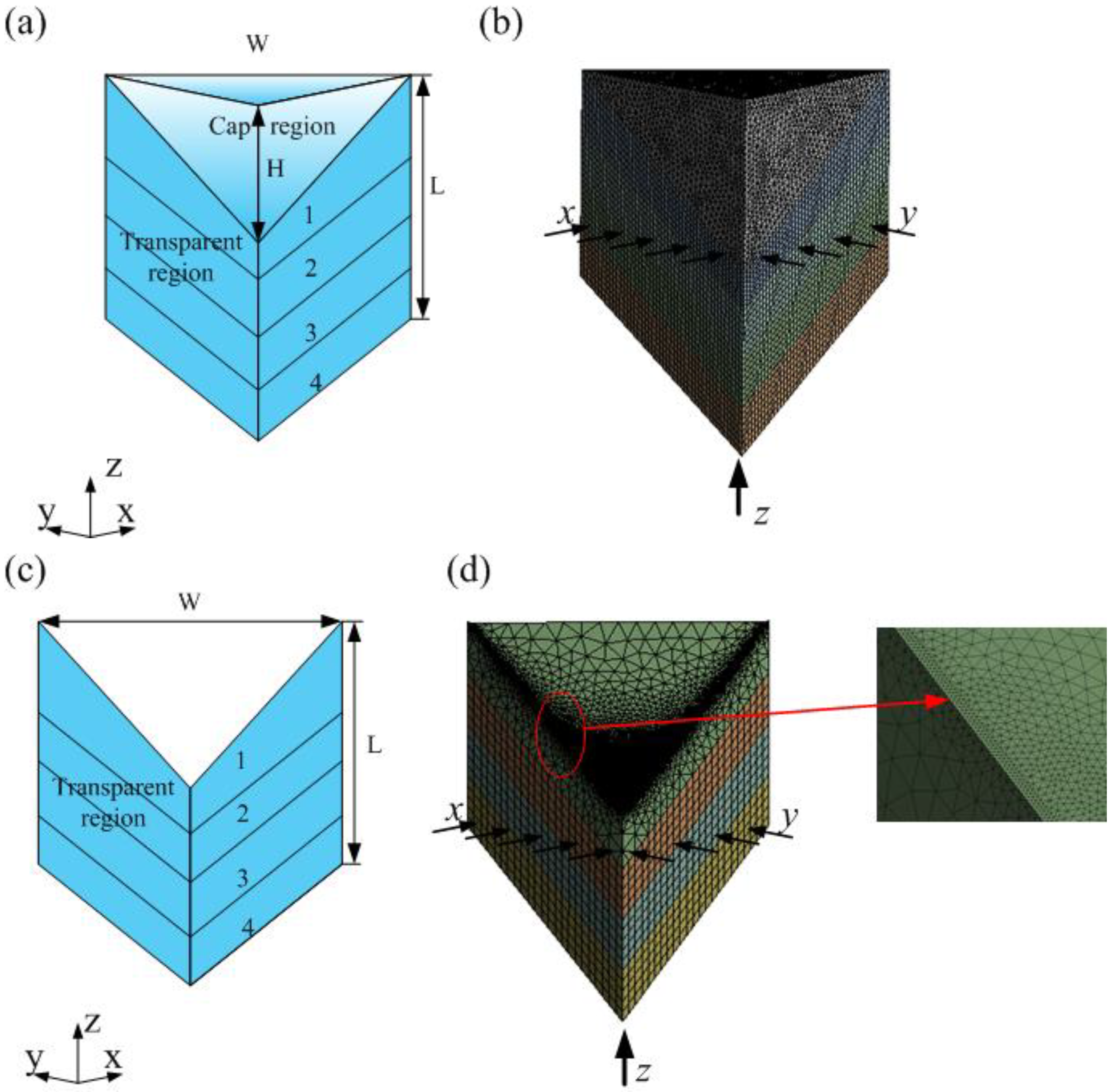
As seen in Figure 1, the cracking mainly occurs after the cap region was complete, during the conventional growth process. A simulation model was needed that includes the cap region and a certain length of the transparent region, from which crystals grown with a 10 °C temperature reduction from a saturated temperature of 60 °C are selected. One quadrant of the crystal geometry was used as the simulation domain because of its four-fold symmetry, as shown in Figure 2. Two structure features were taken into account in this simulation because of the temperature reduction rate difference in the seed regeneration stage. When the regeneration was carried out with a constant 0.1–0.15 °C/day temperature reduction rate, the cap region was almost a solid region with inclusions, cracks, and milky regions. In this case, the cap region was set as a solid region with material properties different from the pure KDP crystal, as displayed in Figure 2a. When the cap was restored via the procedure demonstrated by Guohui Li [3], with a temperature decrease rate of 0.3 °C/day, the cap was a box-like structure filled with the growth solution. Therefore, no cap region was included in the calculation model, as shown in Figure 2c, because of the negligible stress produced from the solution to the bulk KDP crystal. As seen in Figure 2a,c, W is the radial dimension, H is the height of the cap region, and L is the height of the transparent region. In the next section, W changed at 20 cm, 30 cm, 40 cm, and 50 cm to investigate the influence of crystal size on thermal stress. Accordingly, H and L changed with W. The length L of the transparent region was divided into four parts, with step-changing CTE values to simplify the mismatch of CTE in the transparent region. The tetrahedral and hexahedral structures were used to mesh the cap and transparent regions, respectively, as shown in Figure 2b. Some regions were refined for the second scenario, as seen in Figure 2d. The mesh design was fine enough to achieve a grid-independent solution. In the calculation of the stress field, a constant temperature of 50 °C was applied to the whole model.

2.2. Thermoelastic Stress Analysis

Growth stress induced by the thermal mismatch in KDP crystals was calculated using the finite-element method in ANSYS Mechanical. We assumed the crystal has a linear elastic behavior, as described by Hooke’s law:
σ = C[ε − α(T − Tref)]
where σ is the stress tensor, ε is the elastic strain, α is the thermal expansion coefficient, and T is the solid body temperature. Tref is the reference temperature, which is the saturation temperature of 60 °C in this calculation. C is the elasticity matrix, which is given as follows [14]:
C = [ C 11 C 12 C 13 0 0 0 C 12 C 11 C 13 0 0 0 C 13 C 13 C 33 0 0 0 0 0 0 C 44 0 0 0 0 0 0 C 44 0 0 0 0 0 0 C 66 ]
where C11 = 71.2, C12 = −5, C13 = 14.1, C33 = 56.8, C44 = 12.6, and C66 = 6.22 (in units of GPa).
In addition, the strain, ε, in Equation (1) is computed based on the displacement field, and can be described by the formula as follows:
{ ε x = u x ε y = v y ε z = w z   γ yz = w y + v z γ xz = u z + w x γ xy = v x + u y }
where εx, εy, εz, γxy, γyz, and γzx are the strain, and u, v, and w are the displacements in the x, y, and z directions, respectively.
The structure constraint was applied to the calculation domain, as shown in Figure 2b,d. Two displacement constraints, ux = 0 and vy = 0, were applied to the symmetry plane of (100) and (010), respectively. Here, wz = 0 was used in the intersection of two symmetry planes. The effects of gravity and buoyancy on the stress in KDP crystals was ignored because of the insignificant stress increase induced by gravity and buoyancy [13,15]. The material properties involved in the simulation are summarized in Table 1. The a- and c-axes correspond to the x- and z-axes, respectively. The KDP crystals belong to a tetragonal crystal system.

3. Results

3.1. Stress in KDP Crystals including the Cap Region

3.1.1. Effect of the Thermal Expansion Coefficient Variation Trend

As indicated in the previous work by our group [5,7], different impurities have diverse effects on the CTE of KDP crystals. Ions such as Mg2+, Al3+, and ClO4 that are used for doping reduce the CTE of KDP crystals, while Na+ and SO42− ions have adverse effects. For KDP crystals grown by the conventional cooling method, impurity concentrations in the solution decrease gradually with the growth moving forward, resulting in a reduction in impurities content in the crystals. Therefore, incremental and diminishing CTE variation tendencies exist, from the cap region to the apex of the transparent region. According to the CTE value of pure KDP crystals and the maximum variable range of 12% induced by impurities [4,7], CTE values in four parts of the transparent region are listed in Table 2. Thermal stress calculations were conducted with a 50 cm KDP crystal. The total height, L, of the crystal is 63 cm, and the height of the cap region, H, is 29 cm. These height values are obtained from the solubility curve of KDP crystals and the actual experiment observation, according to the 10 °C decrease from a saturated temperature of 60 °C.
Figure 3 shows the stress distribution corresponding to the maximum principal stress, σ1, inside the KDP crystal under two change trends of the CTE. The positive and negative stress values demonstrate that the crystal is in tension and compression, respectively. The maximum stress value is listed in Table 2. In case 1 of incremental CTE from the cap region to the growth front, the maximum stress of 5.71 MPa is at the edge of the outside surface, as denoted by the small red flag labeled “Max” in Figure 3a. High stresses occur in the cap region and the crystal periphery. The stress is very small, even for compressive stress in the interior of the transparent region. In case 2, the maximum stress is 3.97 MPa, located at the edge of the cap region; this location is consistent with the actual crack initiation position, as seen in Figure 1. High stresses are also distributed in the cap region. Nevertheless, stresses inside the pure crystal are larger than those in case 1, and no compressive stress occurs.
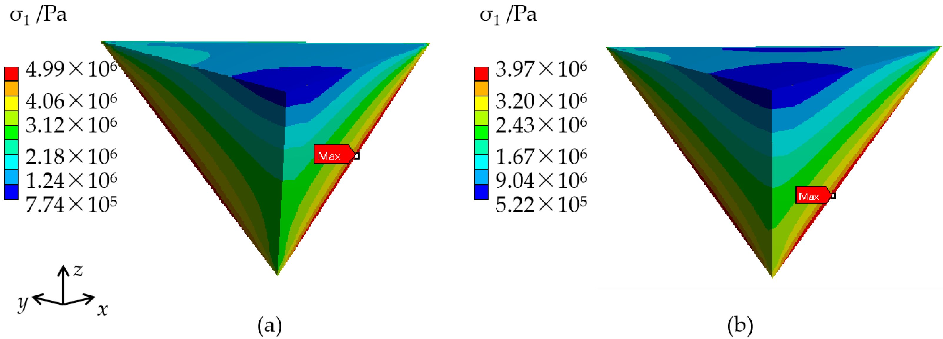
Figure 4 shows a quite similar stress distribution in the cap region under two conditions; one slight difference is that the maximum stress is larger for case 1. It is reasonable to deduce that the gradually increased CTE (case 1) has a higher risk of triggering crystal cracking.

3.1.2. Effect of the Thermal Expansion Coefficient Changing Range

The relatively magnified CTE variation range of 12% applied in the above section is produced by a high-concentration (1000 ppm) doping of SO42− impurities [7]. However, the raw materials used for KDP crystal growth do not reach such a high ion concentration without extra dopants. As Liu [4] measured for a practically grown large-size KDP crystal, the maximum CTE difference is 3.7% and 4.8%, respectively, along the x-axis and z-axis. These values are far different from the CTE variation range of 12%; thus, it is meaningful to further investigate the effects of a small CTE gradient on the growth stress of KDP crystals. A variable CTE based on the narrow range of 3.7% and 4.8% is listed in Table 3.
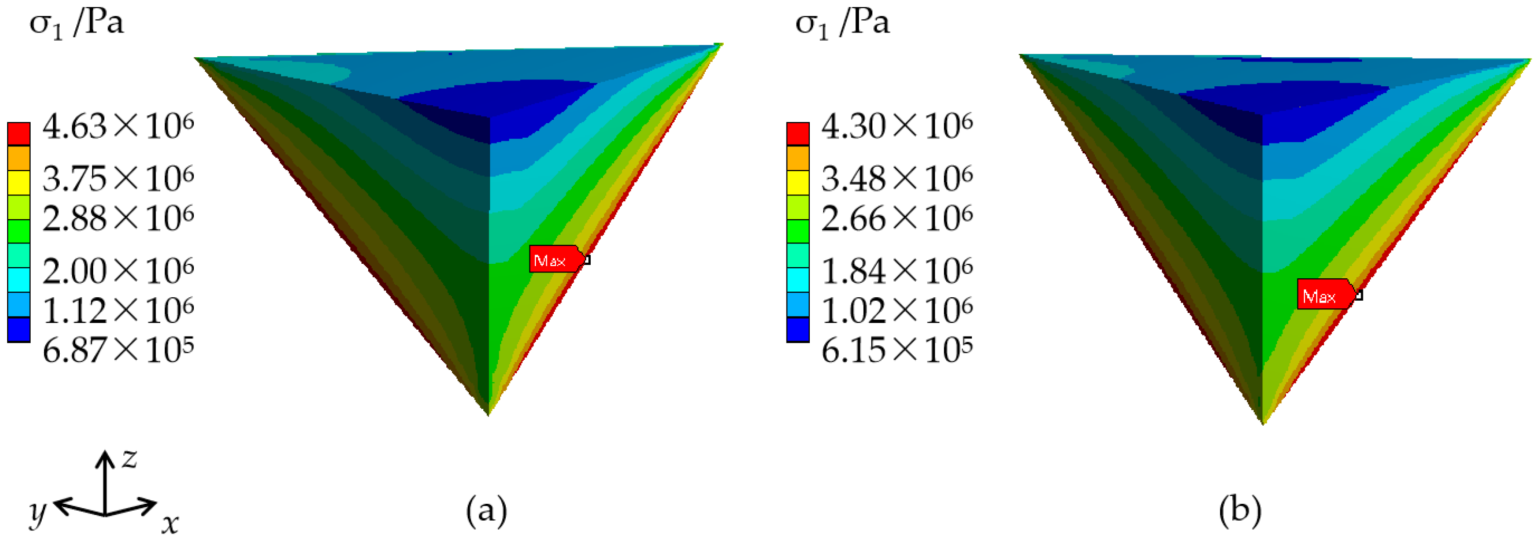
Figure 5 displays the stress distribution of the KDP crystals’ cap region, calculated from the lower difference in CTE under two scenarios. The maximum stress values are listed in Table 3. The results indicate that for case 1 (where CTE gradually increases from the cap region to the growth front), the decreased CTE gradient reduces the maximum stress of the cap region, from 4.99 MPa to 4.63 MPa. It is worth noting that for case 2 (where CTE gradually decreases from the cap region to the growth front), the maximum stress of 4.30 MPa of the cap region, calculated from the low CTE gradient, is larger than the stress of 3.97 MPa that was obtained from the high CTE gradient. This phenomenon may be explained by the fact that material property difference, especially the CTE difference between the cap region and its close vicinity (transparent region 1, marked in Figure 2a) plays a decisive role in the stress value of the edge of the cap region. The CTE difference between the cap region and transparent region 1 from Table 3 (a-axis: 48.94–27.1, c-axis: 48.94–46.7) is larger than that from Table 2 (a-axis: 48.94–29.1, c-axis: 48.94–50.0); herein, the calculated stress (4.30 MPa) from CTE in Table 3 is higher than that (3.97 MPa) from Table 2.

3.1.3. Effect of the Thermal Expansion Coefficient Variation in One Direction

As an anisotropic material, the KDP crystal presents different CTE variations along the x-axis (radial direction) and z-axis (vertical direction). To provide a qualitative conclusion regarding CTE nonuniformity, to establish along which direction the leading cause of high stresses will appear, it is necessary to analyze the effect of the CTE variation along one direction. The CTE of the four parts of the transparent region is listed in Table 4. From the cap region toward the growth front, diminishing values with a varied range of 12% are used.
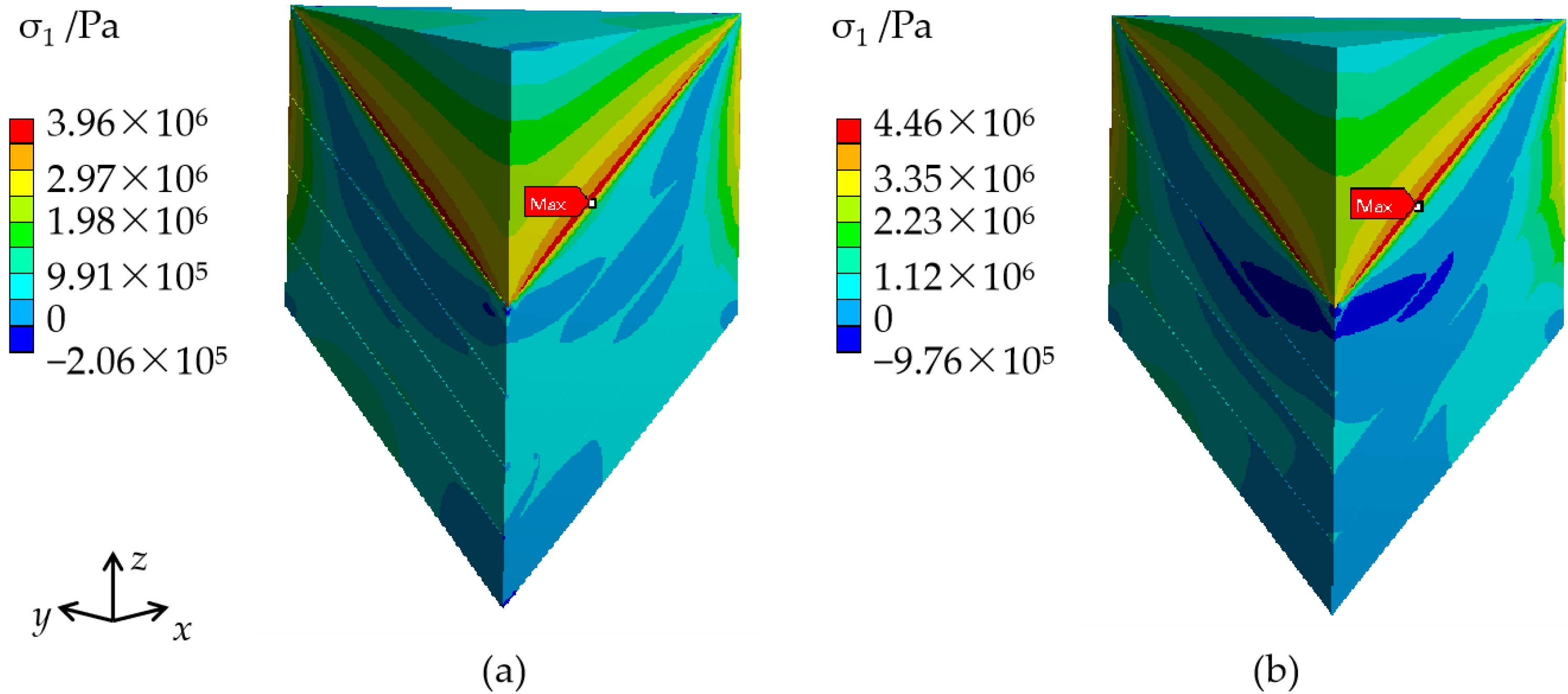
Figure 6 shows the stress distribution of KDP crystals calculated from the corresponding CTE values in Table 4. From Figure 6a, it can be seen that the CTE variation only along the radial direction produces maximum stress of 3.96 MPa, which is similar to the value of 3.97 MPa in Figure 4b. However, when the CTE gradient only exists along the vertical direction, the maximum stress is 4.46 MPa (seen in Figure 6b).
As discussed before, the stress at the edge of the cap region is significantly influenced by the CTE difference between the cap region and its close vicinity (transparent region 1). A CTE values comparison of transparent region 1 in Table 4 (case 2-a, 29.1⊥c, 44.6//c) and in Table 2 (case 2, 29.1⊥c, 50.0//c) indicate a mismatch of CTE along the c-axis. The CTE difference in the cap region along the c-axis in Table 4 (44.6–48.94) increases compared to that in Table 2 (50–48.94). However, this difference does not induce a stress change (from 3.97 MPa to 3.96 MPa). Similarly, the difference in CTE values along the a-axis between the cap region and transparent region 1 increases in Table 4 (case 2-b, 48.94–26.1) compared to that in Table 2 (case 2, 48.94–29.1), combining the maximum stress increase at the edge of cap region; from this, it is reasonable to deduce that the CTE difference along the a-axis has more significant effects on the stress at the edge of cap region.

3.1.4. Effect of Crystal Size

When the KDP crystal has cooled by 10 °C from the saturated temperature, the height of cap region H and the length of transparent region L change, depending on the cross-section of the KDP crystals. Table 5 lists the exact dimension values. A diminishing CTE (case 2, as listed in Table 2) is used in this section because of the similar stress distribution in the cap region produced from an incremental or diminishing CTE variation.
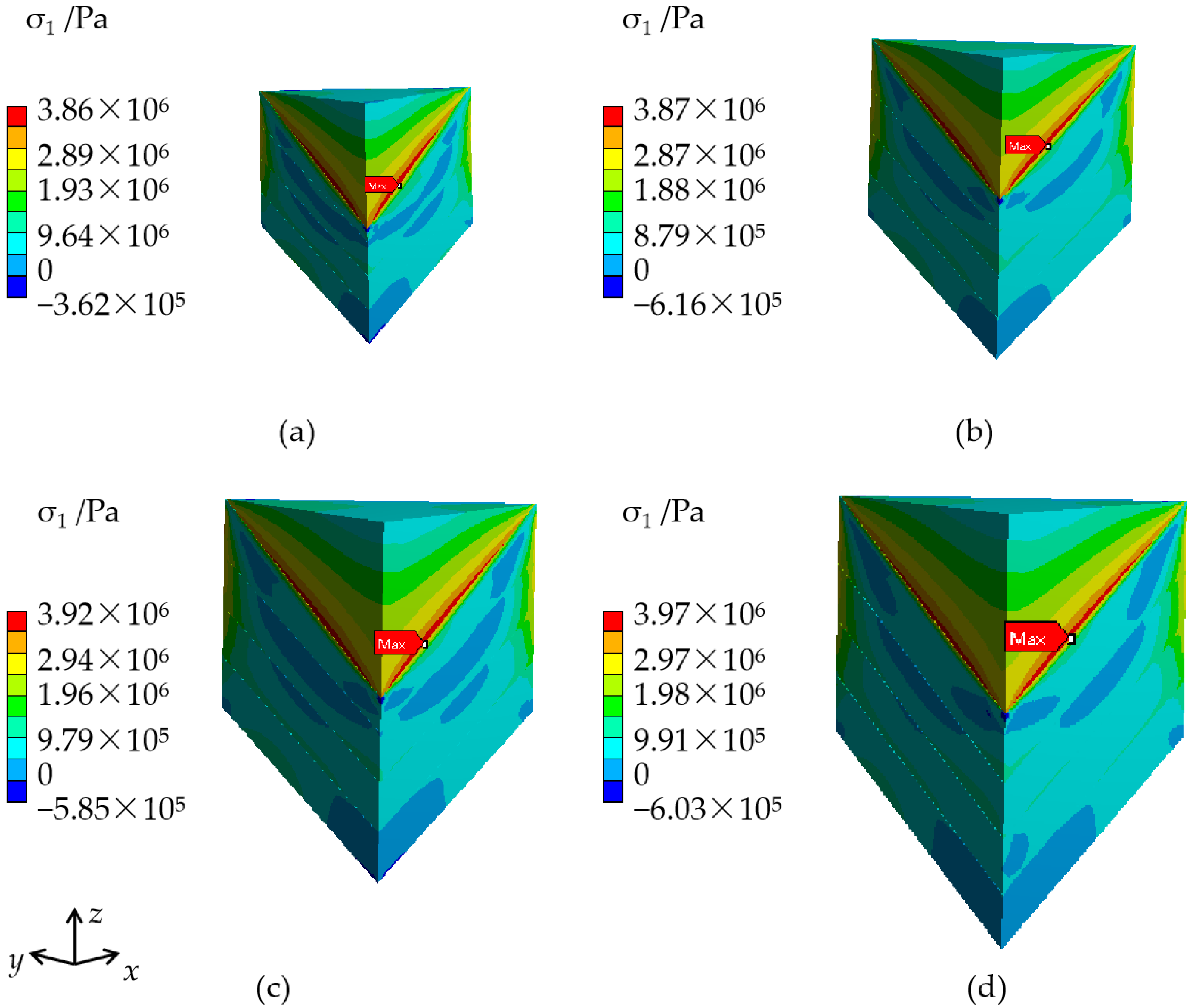
Figure 7 shows the stress distribution inside KDP crystals of different sizes. It can be seen that the stress distribution is barely affected by the size. The slightly increased maximum stress values according to crystal size are listed in Table 5.

3.2. Stress in KDP Crystals without including the Cap Region

3.2.1. Effect of the Thermal Expansion Coefficient Variation Trend

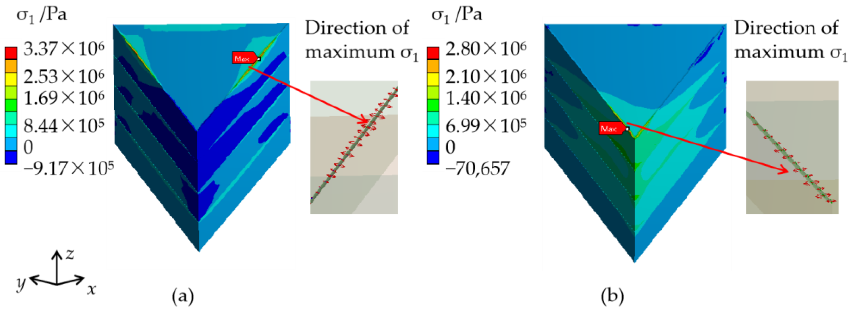
On the basis of the CTE values listed in Table 2, the stress distribution calculated for 50 cm KDP crystals without including the cap region is displayed in Figure 8. The maximum stress information, such as the values, position, and direction of stresses are listed in Table 6. As seen in Figure 8, the maximum stress is at the edge of the interface of the cap region and transparent region. The maximum stress of case 1 (where CTE gradually increases from the cap region to the growth front) is 3.37 MPa, located near the outside surface. Low stresses, even compressive stresses with values less than zero, are present in the central part. In case 2 (where CTE gradually decreases from the cap region to the growth front), the largest stress value of 2.8 MPa is distributed in the interior near the apex of the cap region. Moreover, a noticeable difference from case 1 is that the high stresses of case 2 occur at the inside of the KDP crystal, while the low stresses occur at the periphery. The directions of the maximum σ1 under the two scenarios are vertical to the planes of (010) and (100), respectively; it is easy to produce cracks parallel to the c-axis, and this phenomenon is consistent with the practical observations. From the comparison of the maximum stress position in case 1 and case 2, the position in case 2 is closer to the actual crack initiation position in Figure 1, implying that there is a higher risk of crystal cracking. Therefore, the CTE setting of case 2 is more dangerous.

3.2.2. Effect of the Decreased Thermal Expansion Coefficient Changing Range

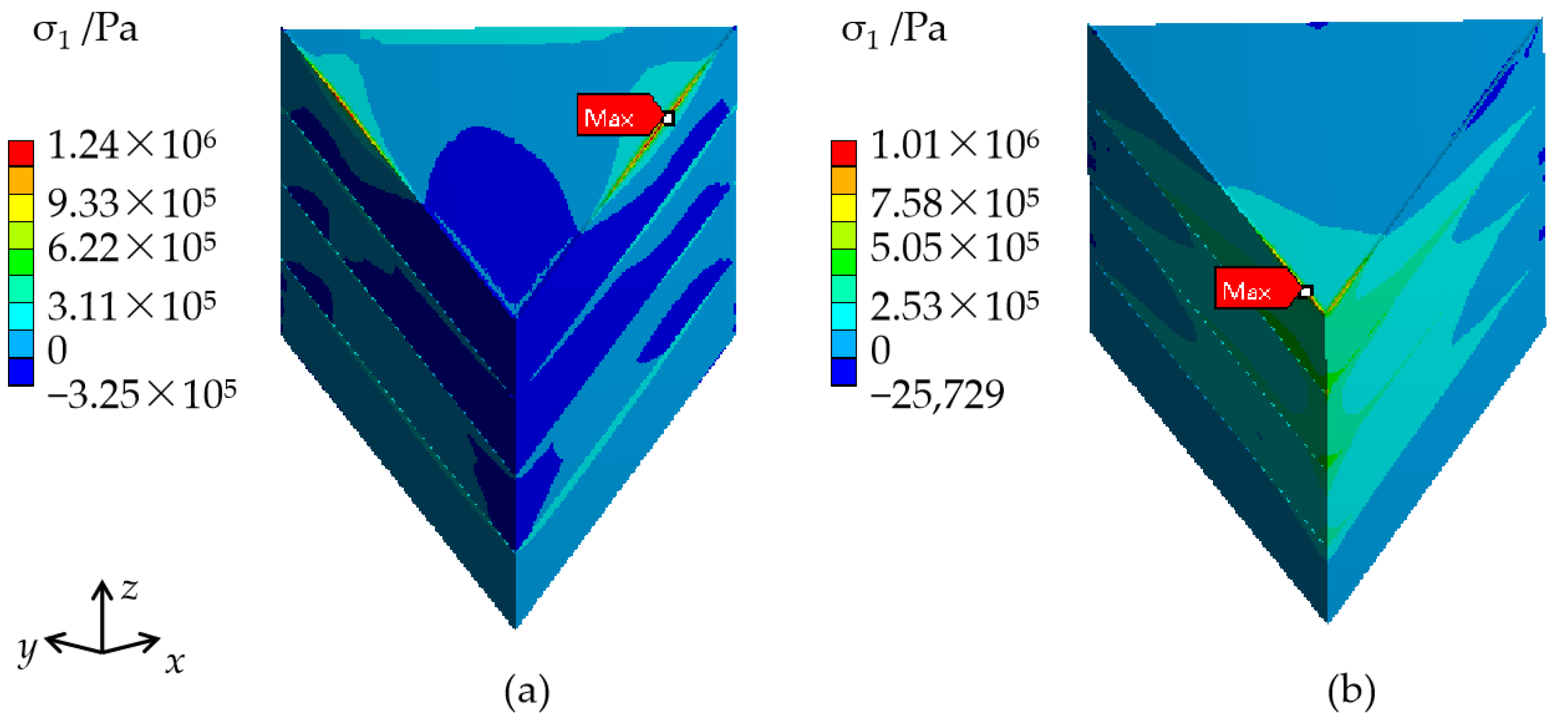
Figure 9 shows the stress distribution in a 50 cm KDP crystal, calculated from the CTE design in Table 3 without including the cap region. The stress distribution is similar to that in Figure 8. Nevertheless, compared to Figure 8, the decreased CTE gradient produces a lower maximum σ1, from 3.37 MPa to 1.24 MPa for case 1, and from 2.80 MPa to 1.01 MPa for case 2. The stress change is in proportion to the variations in CTE.

3.2.3. Effect of the Thermal Expansion Coefficient Variation along One Direction

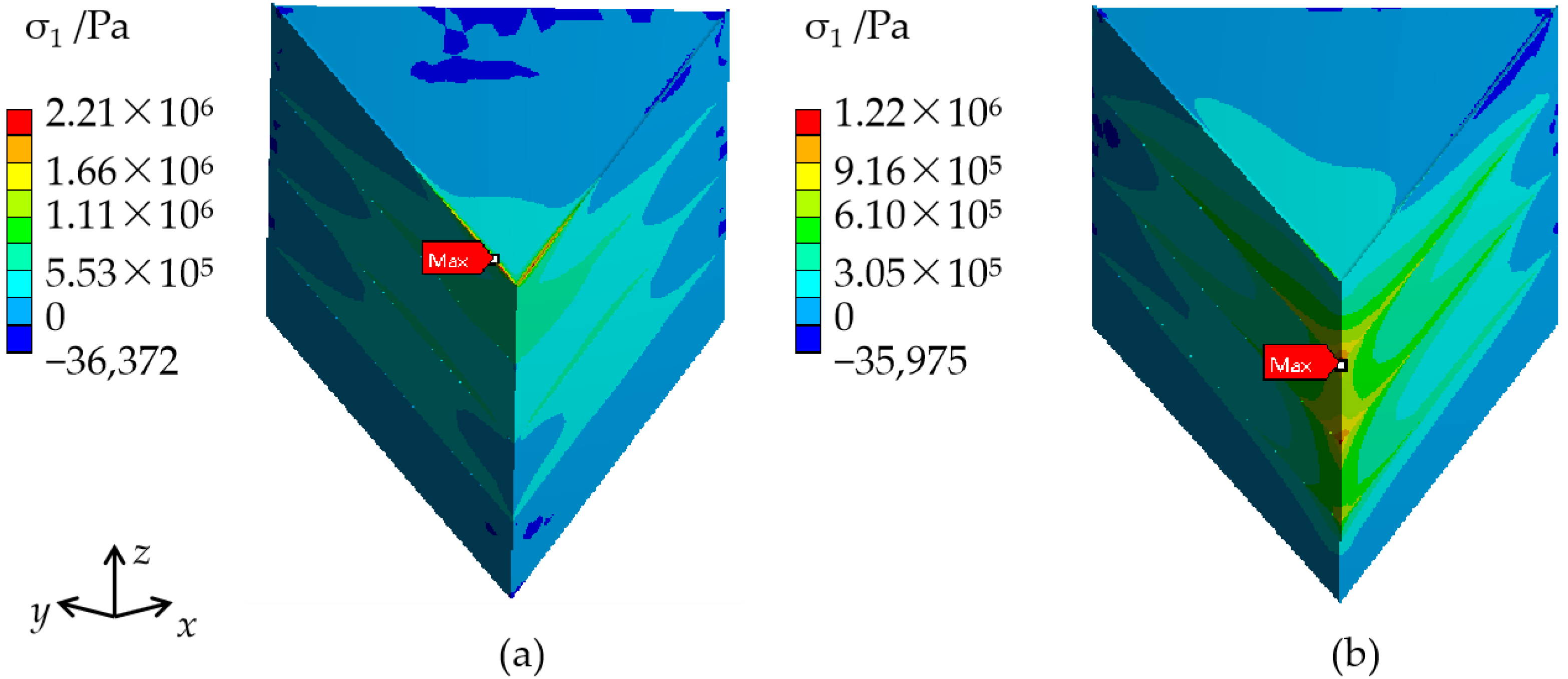
Figure 10 shows the stress distribution inside a 50 cm KDP crystal, calculated from the CTE setting in Table 4 without including the cap region. When the CTE only changes along the x-axis, the computed maximum σ1 position shown in Figure 10a is the same as in Figure 8b, and the maximum σ1 value slightly decreases from 2.8 MPa to 2.21 MPa. When the CTE only changes along the z-axis, high stresses concentrate on the junction points of the two parts of the transparent region, which is different from the actual crystal cracking position, as seen in Figure 1. Moreover, the maximum σ1 value is less than that in Figure 10a. Therefore, it is rational to demonstrate that the mismatch of CTE along the x-axis is the main reason for the crystal stress.

3.2.4. Effect of Crystal Size

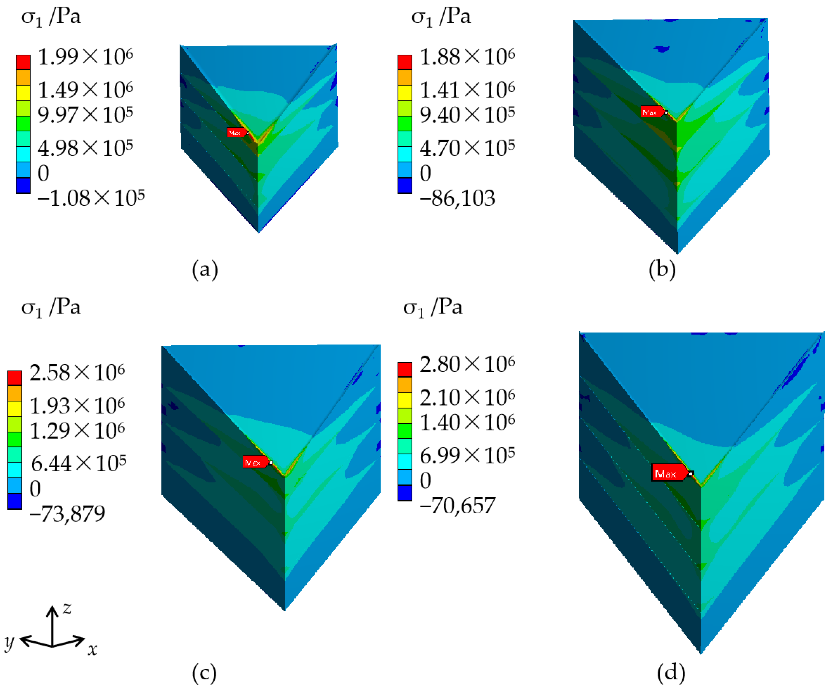
The stress distribution in the KDP crystals of various dimensions, without including the cap region, is displayed in Figure 11. The transparent height, H, and CTE settings involved are based on the values in Table 4 and Table 2 (case 2), respectively. Table 7 lists the maximum stress values. It can be seen from the results that the stress distribution is not affected by the size change. High stresses are located in the interior, and stresses in the periphery are low. The maximum stress increases gradually with the size enlargement. When the crystal size changes from 30 cm to 40 cm, the largest stress values increase drastically, at a ratio of 37%; this may explain the significantly increased cracking potential of KDP crystals when the dimension is larger than 40 cm, during the actual growth process.

4. Discussion

For KDP crystals grown by the traditional method at a low cooling rate (where the cap region forms a solid region), the material property difference between the cap region and its close vicinity (part 1 of the transparent region) is the leading cause of high stresses. Significantly, the CTE difference along the x-axis between the cap region and its close vicinity plays a major role in stresses over the z-axis. A small CTE difference between the cap region (48.94 × 10⁻⁶ (K−1)) and its close vicinity (about 26.1 × 10⁻⁶ (K−1)⊥c 44.6 × 10⁻⁶ (K−1)//c) is necessary to reduce the growth stress of KDP crystals. Therefore, impurities from ions such as Mg2+, Al3+, and ClO4 that decrease the CTE of KDP crystals need to be eliminated in the raw material for KDP crystal growth. Similarly, impurities from ions such as Cs+, Mg2+, ClO4-, and SO42− that produce a more significant effect on CTE along the x-axis than on the z-axis also need to be removed from the raw material [5].
Furthermore, the structure feature of a large-sized traditionally grown crystal cap region is another reason for crystal cracking, except for the high stresses in the cap region and its close vicinity. Typically the region occupied by the regenerated seed and its close vicinity has many structural defects, which give rise to a large number of dislocations in the adjacent growing crystal [2], causing a high risk of cracking.
When the cap region is a box-like structure filled with solution (without including the cap region in the calculation), a mismatch of CTE in the transparent region is the main reason for high stresses; an increased CTE gradient results in a stress increase.
The calculated stresses in this work are generally less than the fracture strength of 6.67 MPa [17] and the fracture stress of 7.69 MPa [12] of a small KDP crystal. However, the cracking of large-sized crystals sometimes occurs in a practical experimental observation. This phenomenon may be explained by the size effect. Generally speaking, the fracture strength of a brittle material is dominated by the defects in it; the strength varies greatly with the defect size. With an increase in crystal size, the appearance probability of a large-sized defect also increases [18]. The Weibull weakest-link model leads to a strength dependency on specimen size, which can be described as in [19]:
σ 1 σ 2 = ( V E 2 V E 1 ) 1 / m
where σ1 and σ2 are the mean fracture stress of type 1 and type 2 specimens, which may have different sizes, VE1 and VE2 are the effective volumes, and m is the Weibull modulus [20,21].
On the basis of Equation (4) and a fracture stress of 7.69 MPa [12] in a traditionally grown small KDP crystal, its height-width ratio is similar to that of crystals used in this work. The predicted fracture stress values in the different sizes of crystals are listed in Table 7. The Weibull modulus of 5.05 was obtained from the bending strength measurement of the KDP crystals [22]. It can be seen from Table 7 that the estimated fracture stress decreases with the crystal size. When the crystal size reaches 40 cm and 50 cm, the calculated stresses under the conditions of including (3.92 MPa, 3.97 MPa) and not including the cap region (2.58 MPa, 2.80 MPa) are both larger than the estimated fracture stress (1.72 MPa, 1.50 MPa) for the corresponding sizes of crystals, indicating a high cracking potential.
The present study suggests that understanding the stress induced by the mismatch of CTE is essential. To successfully grow a large-sized KDP crystal that satisfies its applications as an electro-optic switch and as frequency converters in ICF engineering, it is crucial to purify the raw materials to decrease the impurity effect, accelerate the cooling rate in the seed regeneration for the formation of a box-like structure, and keep a steady thermal field so as to reduce the defect sizes.

5. Conclusions

Numerical simulations were conducted to investigate the growth stresses of KDP crystals of different sizes after cooling by 10 °C from a saturated temperature of 60 °C. Factors that produce stresses were taken into account, such as the difference in material properties between the cap region and transparent region, and the mismatch of CTE in the transparent region. Results indicate that: (1) in the case including the cap region (where the cap region forms a solid region, with a cooling rate of about 0.1 °C/day), the CTE difference, especially that along the x-axis, between the cap region and its close vicinity dominates the high stresses at the edge of the cap region. (2) In the case that does not include the cap region (the cap region regenerates as a box-like structure, with a cooling rate of about 0.3 °C/day), the growth stresses of KDP crystals increase with the CTE gradient in the transparent region. (3) With the crystal sizes increasing, the maximum stress inside the crystal increases slightly. Meanwhile, the fracture stress values that trigger the crystal cracking decrease gradually, meaning that there is a higher cracking potential for a larger crystal. (4) When the mismatch of CTE in the transparent region reaches 12%, crystals with a dimension larger than 0.4 m are in danger of cracking. (5) To decrease the cracking potential of KDP crystals during the growth process, it is important to purify the raw material, accelerate the cooling rate in the initial growth stage, and keep a controlled growth environment.

Author Contributions

Conceptualization, Z.H. and S.W.; methodology, P.H. and S.W.; software, Z.H. and P.H.; validation, Z.H., P.H. and S.W.; formal analysis, Z.H.; investigation, Z.H.; resources, Z.H.; data curation, Z.H.; writing—original draft preparation, Z.H.; writing—review and editing, M.L. and D.H.; visualization, Z.H.; supervision, Z.H.; project administration, S.W.; funding acquisition, S.W. All authors have read and agreed to the published version of the manuscript.

Funding

This research was funded by the Natural Science Foundation of Hunan Province, grant numbers 2021JJ40463 and 2020JJ5463; the project was approved by the Provincial Education Department of Hunan Province, grant numbers 19C1581, 19A425, and 19A420.

Data Availability Statement

Not applicable.

Conflicts of Interest

The authors declare no conflict of interest.

References

  1. Pang, Q.; Shu, Z.; Kuang, L.; Xu, Y. Effect of actual frequency features generated in machining process on the temperature and thermal stress of potassium dihydrogen phosphate crystal. Mater. Today Commun. 2021, 29, 102984. [Google Scholar] [CrossRef]
  2. Zaitseva, N.; Carman, L. Rapid growth of KDP-type crystals. Growth Charact. Mater. 2001, 43, 1–118. [Google Scholar] [CrossRef]
  3. Li, G. Rapid Z-plate seed regeneration of large size KDP crystal from solution. J. Cryst. Growth 2008, 310, 36–39. [Google Scholar] [CrossRef]
  4. Liu, L.; Wang, S.; Liu, G.; Wang, D.; Li, W.; Ding, J. Research on Thermal Expansion Coefficient of Large-aperture KDP/DKDP Crystals. J. Synth. Cryst. 2015, 44, 1443–1447. (In Chinese) [Google Scholar]
  5. Liu, L. Study on the Thermal Property and Uniformity of Large KDP/DKDP Crystals. M.D. Thesis, Shandong University, Shandong, China, 2015. [Google Scholar]
  6. Sun, Y.; Wang, S.; Jiang, T.; Gu, Q.; Wang, B.; Sun, S.; Xu, X.; Ding, J.; Liu, W. Effect of Na+ on the thermal expansion and hardness of KDP crystals. J. Funct. Mater. 2013, 44, 1768–1771. (In Chinese) [Google Scholar]
  7. Sun, Y. Study on the Mechanical Properties and Cracking Phenomenon of KDP Crystal. Ph.D. Thesis, Shandong University, Shandong, China, 2012. [Google Scholar]
  8. Guo, Z.; Yan, S.; Reiter, G. Formation of Stacked Three-Dimensional Polymer “Single Crystals”. Macromolecules 2021, 54, 4918–4925. [Google Scholar] [CrossRef]
  9. Yu, Y.-J.; Byeon, D.-S.; Shin, Y.-J.; Choi, S.-H.; Lee, M.-H.; Lee, W.-J.; Jeong, S.-M. Residual stress analysis of 4H-SiC crystals obtained by a top-seeded solution growth method. CrystEngComm 2017, 19, 6731–6735. [Google Scholar] [CrossRef]
  10. Liu, S.; Wang, Z.; Guo, J.; Shi, Z.; Ren, X.; Yang, Q. Thermal-mismatch-stress induced deformation zone on primary-carbide/austenite interface. Mater. Lett. 2019, 248, 55–59. [Google Scholar] [CrossRef]
  11. Huang, P.; Wang, S.; Wang, D.; Liu, H.; Liu, G.; Xu, L. Study on the cracking of a KDP seed crystal caused by temperature nonuniformity. CrystEngComm 2018, 20, 3171–3178. [Google Scholar] [CrossRef]
  12. Huang, P.; Wang, D.; Li, W.; Liu, H.; Liu, G.; Wang, S. Crack of KDP Crystals Caused by Temperature-nonuniformity. J. Chin. Ceram. Soc. 2018, 46, 929–937. (In Chinese) [Google Scholar]
  13. Huang, P.; Wang, S.; Ding, J.; Wang, D.; Wang, B.; Liu, H.; Xu, L.; Zhang, L.; Li, X.; Liu, Y. Study on the thermal stress evolution in large scale KDP crystals during the crystal extraction process. RSC Adv. 2019, 9, 20706–20714. [Google Scholar] [CrossRef] [PubMed]
  14. Su, R.; Liu, H.; Liang, Y.; Yu, F. Residual thermal stress of a mounted KDP crystal after cooling and its effects on second harmonic generation of a high-average-power laser. Opt. Laser Technol. 2017, 87, 43–50. [Google Scholar] [CrossRef]
  15. Zhang, N.; Zhang, Q.; Wang, S.; Sun, Y. Numerical Simulation Analysis of mechanical effect of large size KDP crystals during the extraction process. J. Funct. Mater. 2011, 42, 2133–2136. (In Chinese) [Google Scholar]
  16. Zhang, Q.; Zhang, N.; Wang, S.; Liu, D. Scale Effect Analysis of Growth Cracking in Large Size KDP Crystals. J. Funct. Mater. 2009, 40, 1584–1587, 1590. (In Chinese) [Google Scholar]
  17. Zhang, Q.; Liu, D.; Wang, S.; Zhang, N.; Mu, X.; Sun, Y. Mechanical Parameters Test and Analysis for KDP Crystals. J. Synth. Cryst. 2009, 38, 1313–1319. [Google Scholar]
  18. Miyazaki, N.; Koizumi, N. Analysis of cracking of lithium tantalate (LiTaO3) single crystals due to thermal stress. J. Mater. Sci. 2006, 41, 6313–6321. [Google Scholar] [CrossRef]
  19. Quinn, G.D. Weibull Strength Scaling for Standardized Rectangular Flexure Specimens. J. Am. Ceram. Soc. 2003, 86, 508–510. [Google Scholar] [CrossRef]
  20. Torres, Y.; Bermejo, R.; Gotor, F.J.; Chicardi, E.; Llanes, L. Analysis on the mechanical strength of WC-Co cemented carbides under uniaxial and biaxial bending. Mater. Des. 2014, 55, 851–856. [Google Scholar] [CrossRef]
  21. Farahani, F.; Gholamipour, R. Statistical weibull analysis of compressive fracture strength of (Zr55Cu30Al10Ni5)99Nb1 bulk metallic glass. J. Alloy. Compd. 2017, 695, 2740–2744. [Google Scholar] [CrossRef]
  22. Huang, P.; Liu, H.; Zhang, L.; Li, X.; Wang, S. Dependence of bending strength on orientations of KDP crystals. CrystEngComm 2022, 24, 1738–1743. [Google Scholar] [CrossRef]
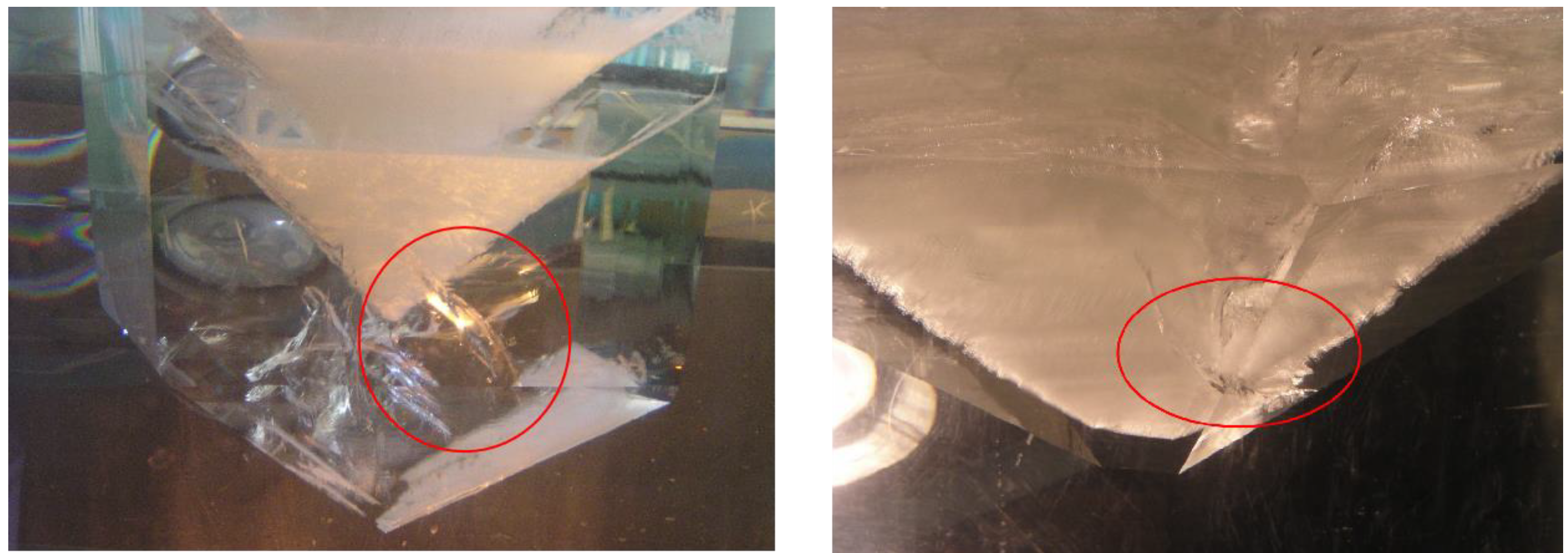
Figure 1. Cracking of KDP (KH2PO4, potassium dihydrogen phosphate) crystals (with an aperture of about 50 cm) during the growth process; the cracks are marked by the red circle.
Crystals 12 01323 g001
Figure 2. (a) Schematic diagram of the calculation model, including the cap region; (b) stress computation grids applied with structure constraints; (c) schematic diagram of the calculation model without including the cap region; (d) stress computation grids applied with structural constraints.
Crystals 12 01323 g002
Figure 3. Stress distribution and the direction of maximum σ1 of KDP crystals in two scenarios: (a) case 1 (CTE gradually increases from the cap region to the growth front); (b) case 2 (CTE gradually decreases from the cap region to the growth front).
Crystals 12 01323 g003
Figure 4. Stress distribution in the cap region of KDP crystals in two scenarios: (a) case 1 (CTE gradually increases from the cap region to the growth front); (b) case 2 (CTE gradually decreases from the cap region to the growth front).
Crystals 12 01323 g004
Figure 5. Stress distribution in the cap region of KDP crystals with a decreased CTE gradient in two scenarios: (a) case 1 (CTE gradually increases from the cap region to the growth front); (b) case 2 (CTE gradually decreases from the cap region to the growth front).
Crystals 12 01323 g005
Figure 6. Stress distribution inside KDP crystals calculated from CTE setting in Table 4: (a) CTE-only changes along the a-axis; (b) CTE-only changes along the c-axis.
Crystals 12 01323 g006
Figure 7. Stress distribution in KDP crystals of various sizes, with the diminishing CTE setting, following case 2: (a) 20 cm, (b) 30 cm, (c) 40 cm, (d) 50 cm.
Crystals 12 01323 g007
Figure 8. Stress distribution and the direction of maximum σ1 in KDP crystals without including the cap region: (a) case 1 (CTE gradually increases from the cap region to the growth front), (b) case 2 (CTE gradually decreases from the cap region to the growth front).
Crystals 12 01323 g008
Figure 9. Stress distribution in a 50 cm KDP crystal, calculated from a decreased CTE gradient: (a) case 1 (CTE gradually increases from the cap region to the growth front), and (b) case 2 (CTE gradually decreases from the cap region to the growth front).
Crystals 12 01323 g009
Figure 10. The stress distribution in KDP crystals with a CTE change only along one direction, without including the cap region: (a) CTE only changes along the x-axis, (b) CTE only changes along the z-axis.
Crystals 12 01323 g010
Figure 11. Stress distribution in KDP crystals of various sizes, calculated from the diminishing CTE setting, following case 2 without including the cap region: (a) 20 cm, (b) 30 cm, (c) 40 cm, (d) 50 cm.
Crystals 12 01323 g011
Table 1. Material properties involved in the simulation (* means that the datum was measured in experiments) [13,16].
MaterialDensity (kg·m−3)Heat Conductivity (W·m−1·K−1)Thermal Expansion Coefficient (K−1)Young’s Modulus
(GPa)
Poisson’s Ratio
KDP crystal23381.34⊥c 1.21‖cList in the next table according to different casesRepresented by Equation (2)
Cap region2200 *1.09 *4.894e−5 *19.630.06
Table 2. Thermal expansion coefficient values ×10−6 (K−1), with different variation trends in four parts of the transparent region and the cap region, and the maximum stress inside the crystal.
1234Cap RegionThe Maximum σ1 (MPa)
Case123.1⊥c
39.2//c
24.1⊥c
41.0//c
25.1⊥c
42.8//c
26.1⊥c
44.6//c
48.94
(isotropy)
5.71
Case229.1⊥c
50.0//c
28.1⊥c
48.2//c
27.1⊥c
46.4//c
26.1⊥c
44.6//c
48.94
(isotropy)
3.97
Table 3. Thermal expansion coefficient values ×10−6 (K−1) with a narrow range variation in the transparent region, cap region, and maximum stress in the crystal.
1234Cap RegionMaximum σ1 of the Cap Region (MPa)
Case 125.1⊥c
42.5//c
25.5⊥c
43.2//c
25.8⊥c
43.9//c
26.1⊥c
44.6//c
48.94
(isotropy)
4.63
Case 227.1⊥c
46.7//c
26.7⊥c
46.0//c
26.4⊥c
45.3//c
26.1⊥c
44.6//c
48.94
(isotropy)
4.30
Table 4. Diminishing CTE values, varied along one direction ×10−6 (K−1).
1234
Case2-a
(CTE change along the radial direction)
29.1⊥c
44.6//c
28.1⊥c
44.6//c
27.1⊥c
44.6//c
26.1⊥c
44.6//c
Case2-b
(CTE change along the vertical direction)
26.1⊥c
50.0//c
26.1⊥c
48.2//c
26.1⊥c
46.4//c
26.1⊥c
44.6//c
Table 5. Exact growth height of KDP crystals of different sizes when the KDP growth temperature has been lowered by 10 °C from the saturated temperature, along with the maximum σ1 values inside the KDP crystals.
Radial Dimension of KDP Crystals (cm)The Height of the Cap Region (cm)The Height of the Transparent Region (cm)The Maximum σ1 (MPa)
2012133.86
3017213.87
4023273.92
5029343.97
Table 6. The maximum σ1 of the KDP crystals under the two scenarios of the CTE setting.
The Maximum σ1 (MPa)Position of the Maximum σ1Direction of the Maximum σ1
Case 13.37Edge of the interface of the cap region and the transparent region near the outside of the crystalVertical to the (010) plane
Case 22.80Edge of the interface of the cap region and the transparent region close to the apex of the cap regionVertical to the (100) plane
Table 7. Comparison of estimated fracture stress to the calculated maximum stress from the CTE setting of case 2, in different sizes of crystals.
Crystal Dimensions (cm)Estimated Fracture Stress σW
(MPa)
The Maximum Stress of Crystals, including the Cap Region(MPa)The Maximum Stress of Crystals, without including the Cap Region (MPa)
3.2 × 3.2 × 4.07.69----
20 × 20 × 252.593.861.99
30 × 30 × 382.033.871.88
40 × 40 × 501.723.922.58
50 × 50 × 631.503.972.80
Publisher’s Note: MDPI stays neutral with regard to jurisdictional claims in published maps and institutional affiliations.