Article

Off-Axis Polarization Volume Lens for Diffractive Waveguide

Joint International Research Laboratory of Information Display and Visualization, School of Electronic Science and Engineering, Southeast University, Nanjing 210096, China
*
Author to whom correspondence should be addressed.
Crystals 2023, 13(3), 390; https://doi.org/10.3390/cryst13030390
Submission received: 2 February 2023 / Revised: 14 February 2023 / Accepted: 22 February 2023 / Published: 24 February 2023
(This article belongs to the Section Liquid Crystals)

Abstract

:
In augmented reality diffractive waveguide technology, the light field needs to be collimated before being transmitted into the diffractive waveguide. Conventional schemes usually require additional collimating optics to collimate the light from the micro-image source and guide it into the waveguide in-coupling elements. In order to meet the needs of head-mounted devices and further miniaturize the equipment, this paper proposes a waveguide device that combines collimation and coupling by using a reflective polarization volume lens (PVL). A related model is also established and simulated to calculate the diffraction and transmission characteristics of the PVL element, and is then improved to fit the experiment. The diffraction lens studied in this paper has high diffraction efficiency with a large off-axis angle, which can fold the optical path and reduce considerably the volume of the optical system when applied to the waveguide system.

1. Introduction

In the field of head-mounted augmented reality (AR) displays, optical waveguide technology has become the mainstream choice in recent years [1,2,3,4]. Diffraction elements are widely used as optical coupling devices in optical waveguide technology solutions, such as Pancharatnam–Berry phase lenses (PBLs) [5,6,7], volume holographic gratings (VHGs) [8], polarization volume gratings (PVGs) [9,10,11,12,13], etc. Among them, PVG has been widely used in optical waveguide technology in recent years. This is because PVG has a significant advantage over other technological solutions. As a liquid crystal grating, PVG has is characterized by a circular polarization response, high diffraction efficiency, wide response bandwidth, large diffraction angle, and high transmittance to ambient light, adapted to the request of waveguide technology. Currently, a refractive lens group is used as collimated optics when PVG is applied to the system. However, because of the large size and the complexity of the glass collimated optics, which need improvement, there may be better solutions. Therefore, a polarization volume lens (PVL) simulated model was built as a new type of diffractive element to improve the system’s performance by simplifying the structure, combining the collimating optics and coupling elements, which has a potential application value in near-eye displays.
Specifically, PVL is a proposed liquid crystal lens based on the PVG structure. It not only has the characteristics of PVG’s polarization selectivity and single-order high-efficiency diffraction, but can also converge the incident circularly polarized light with a larger off-axis diffracted angle. Theoretically, due to the elastic free energy of liquid crystals, the liquid crystal molecules in PVL have similar tilt characteristics to PVG [14,15]. Compared to PVGs, the main structural difference of PVLs is that PVL is an aperiodic structure, which means its refractive index planes are curled regularly to change its optical phase, utilizing its characteristic plane off-axis diffraction element to improve space utilization. The reflective PVL, which is based on the off-axis lens structure, has the advantages of small size and light weight. Made of liquid crystal material, the PVL is based on the Bragg diffraction effect. Its Bragg period is a function of the spatial position. This inspiring structure makes PVL produce a convergence effect on the incident left-handed or right-handed circularly polarized light. This paper mainly focuses on the reflective characters of PVL, along with the application of polarization selectivity. The different polarized PVL layers can be combined for variable applications. As a traditional solution, the regular holographic optical elements have already been simulated in multi-aspect. However, PVL is based on liquid crystals with anisotropic permittivity, which leads to the differences between PVL and regular holographic lenses, and thus needs simulations.
The PVL structure has been experimentally prepared and optimized. In 2020, Yin et al. experimentally prepared a PVL with a fixed central diffraction angle of 45° and a 0.825 f-number [16], which can improve the field of view (FOV) of the waveguide system. In 2021, the same research group proposed a scheme to improve FOV by stacking PVLs [17,18]. In 2022, they proposed the application of increasing viewpoints based on the polarization characteristics of PVL [19]. At present, PVL-related works are mainly based on experiments, while the results of simulations of PVL structures have not yet been reported. However, limited by the material used in the experiment, the preparation environment, and other possible limitations of technique, the performance of the PVL structure may not be evaluated thoroughly. However, the simulation work helps further evaluate the performance of the PVL structure comprehensively and theoretically, without the limitations of experimental conditions.
In this paper, the PVL was modeled, and the simulated diffraction performance was calculated according to the structure of PVL and the experimental preparation process under both ideal and the non-ideal conditions. Based on the axisymmetric structural characteristics of PVL, two-dimensional modeling of PVL was carried out, whose diffraction efficiency, focus position, and the curve of change in incident angle were calculated by simulation. The applications for waveguides were proposed and polarization multiplexing simulation diagrams were displayed. Our work may be instructive to the design of PVL and would help reduce the volume of the optical system and the complexity of the collimated optical path.

2. Methods and Results

Two reflective PVL structures were modeled and simulated in this paper, respectively under ideal conditions and non-ideal conditions. Under the ideal condition, where the longitudinal period varies by the spatial position, the diffractive properties of PVL as a lens can be clearly exhibited. By contrast, under non-ideal conditions, the longitudinal period of the material is constant in one liquid crystal layer, which is closer to real situations. The modeled structures achieved good focusing characteristics while maintaining a large diffraction angle and high diffraction efficiency under both conditions.

2.1. The Ideal PVL Model

Since the model structure of PVL is a three-dimensional axisymmetric off-axis lens, in order to simplify the modeling calculation, we took the plane passing through its symmetry axis (i.e., the optical axis of the PVL) as the 2D model. If the symmetry axis is set as the y-axis, the center of the incident beam can be in the x–y plane, and the center of the optical path of the corresponding diffracted beam is also located in this plane.
In the space system mentioned above, it is assumed that the plane where the PVL contacts the waveguide material is the x–z plane, and the focus coordinates of the PVL are designed to be ( x 0 , y 0 ) . If the light beam incident on the point ( x , y ) has a diffraction angle φ o , then according to the geometric relationship, it should have:
φ o = tan 1 ( x x 0 y y 0 ) .
According to the geometric relationship of the reflection after the incidence, the relationship between the tilt angle θ of the refractive index plane at the ( x , y ) point inside the PVL should be:
θ = 1 2 tan 1 ( x x 0 y y 0 ) .
According to Bragg’s theorem [10], for a beam of normal incidence, the Bragg period Λ B of PVL can be calculated by:
2 n eff Λ B cos θ = λ 0 .
where λ 0 is the vacuum Bragg wavelength of the PVL. If n o and n e are the ordinary and extraordinary refractive indices, respectively, the average refractive index n eff of an anisotropic medium is defined as follows [10]:
n eff = n e 2 + 2 n o 2 3 .
Additionally, according to the geometric relationship, the relationship between the lateral period Λ x , the longitudinal period Λ y , the Bragg period Λ B , and the inclination angle θ of the refractive index plane are expressed as:
{ Λ x = Λ B sin θ Λ y = Λ B cos θ ,
Λ B ( x , y ) = λ 0 2 n eff cos θ   ,
Λ x ( x , y ) = λ 0 n eff sin 2 θ ,
Λ y ( x , y ) = λ 0 2 n eff cos 2 θ .
By combining Equations (2), (7), and (8), the optical axis phase formula of PVL (left-handed) can be obtained:
α = π n eff λ 0 ( ( x x 0 ) 2 + ( y y 0 ) 2 y ) .
The inclination angle of the reflective PVL’s refractive index plane ranges from 0 to nearly 45°. Meanwhile, a high diffraction efficiency can be maintained theoretically.
According to the above modeling, the diffraction characteristics of PVL were simulated and analyzed based on the commercial finite element software COMSOL. When designing and constructing a PVL model (hereinafter also called the ideal PVL model) with a central wavelength of 550 nm in a vacuum responding to left-handed circular polarization, the PVL model will diffract and converge the incident 550 nm left-handed circularly polarized light, while the incident right-handed circularly polarized light will directly pass through because of the polarization selectivity of the PVL structure. The polarization selectivity of PVL is inherited from the properties of PVG [10]. The simulation of this model is mainly based on the diffraction characteristics of PVL near the optical axis of the lens.
Figure 1 is a section view of the PVL optical axis rotation phase. The ordinary refractive index of the liquid crystal is no = 1.5 and the extraordinary refractive index is ne = 1.7. The mesh size was set to be small for the convenience of simulation calculation, so the model was scaled down.
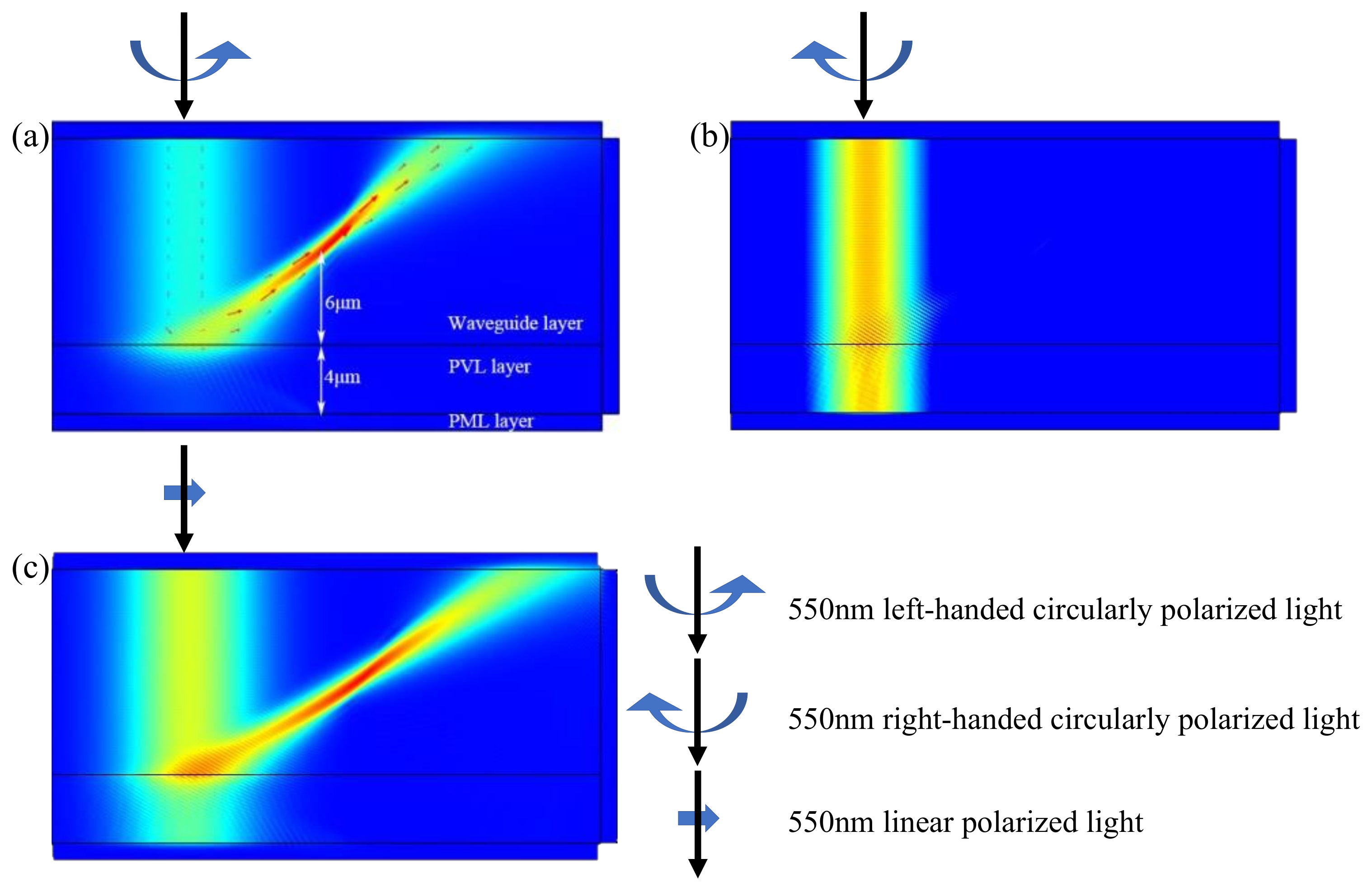
In this simulation, the focus was set to 6 μm above the contact plane between the PVL and the waveguide material. That is, the focal length was 6 μm (shown in Figure 2). The PVL thickness was set to 4 μm, so the PVL region was [−4, 0] μm. The upper part of this region is the waveguide dielectric region, and the lower part is the perfectly matched layer region. Cases of the left-handed polarized light incident, right-handed polarized light incident, and linearly polarized light incident were simulated and are shown in Figure 2. The incident light had a wavelength of 550 nm in all these cases. The polarization selectivity of the PVL structure can be seen. The 550 nm left-handed circularly polarized light was diffracted and converged, while the right-handed circularly polarized light directly passed through.
As a holographic lens, PVL has wavelength selectivity and angle selectivity to diffraction efficiency, which is similar to PVG. By setting the vicinity of the axisymmetric center in the PVL structure as the incident area, the diffraction efficiency curve changing with wavelength and the incident angle were obtained by simulation. When the beam is vertically incident on the center of the PVL structure, the wavelength bandwidth of the diffraction efficiency of PVL exhibits similar characteristics to that of PVG. That is, the diffraction efficiency remains high within the bandwidth around the central wavelength (550 nm in this paper), while outside this range, the diffraction efficiency is low and has obvious wavelength selectivity. When the incident angle varies from about −10° to 10°, the diffraction efficiency of PVL remains at a high level. However, with the increase in the absolute value of the incident angle, the diffraction efficiency of PVL decreases, showing angle selectivity.
When the light is perpendicularly incident on the center of the PVL structure, the wavelength bandwidth of the diffraction efficiency exhibits similar characteristics to that of PVG. That is, the diffraction efficiency is kept high in a certain bandwidth around the center wavelength (550 nm in this paper), showing apparent wavelength selectivity. When the incident angle varies from about −10° to 10°, the diffraction efficiency of PVL remains at a high level. However, as the absolute value of the incident angle increases, the diffraction efficiency of PVL decreases significantly, which shows angular selectivity.
By changing the wavelength of the vertically incident light, the focus position change curve and diffraction efficiency curve of the PVL model can be obtained, as shown in Figure 3 (the focal length is 6 μm). The theoretical focus lengths in the figure were obtained by paraxial approximation according to the structural characteristics of PVL when the light beam is perpendicular to the structural center of PVL.
When the incident angle is approximately −10° to 10°, the convergence phenomenon of light can clearly be seen in the simulated image. The simulation also shows that the diffraction efficiency of the beam is high in this range. In this interval, the ordinate of the focus remains basically unchanged, while the abscissa of the focus varies with the incident angle. The theoretical value is used as a reference shown in the figure, which agrees with the simulated experimental value.
Due to the non-periodicity of PVL, it is difficult to quantify the diffraction efficiency of the whole PVL. In this paper, the PVL incident area was divided into several blocks according to the diffraction direction, and their respective diffraction efficiencies were measured. The curves of diffraction efficiency as a function of the center diffraction angle were obtained (the focal length was 6 μm). With an incidence at a position closer to the center of the structure (the abscissa was 0), the diffraction efficiency is maintained at a high level close to 1. However, the diffraction efficiency decreases as it moves away from the center of the structure. Based on the PVL model, changing the preset diffraction angle (or incident position) of the incident beam, and measuring the actual focus of the PVL model on the focal plane, the trend of the actual focus abscissa can be obtained, as shown in Figure 3a.
When the beam moves from the position of the optical axis to both sides, the position of the actual focus gradually tends to move away from the preset focus. Figure 3b shows the relationship between the diffraction efficiency and the incident position. It can be seen that diffraction efficiency decreases with the deviation of the incident position from the optical axis. In Figure 3b, the incident position changes from the middle to the side (the diffraction angle changes from small to large). This shows that, when the focal length remains unchanged, although the diffraction efficiency of PVL is not limited by the diffraction angle, the beam still needs to be incident within a certain range (the central diffraction angle should be less than about 70°) to have a better convergence effect.

2.2. The Non-Ideal PVL Model

The PVL’s dispersion equation is inherited from PVG as follows:
sin ( φ o ) = m λ n g l Λ x + s i n φ i n g l .
In this formula, φ i is the incidence angle from air to PVL and φ o is the diffraction angle. m is the diffraction order, and the main diffraction order in PVL and PVG is +1. n g l is the refractive index of the glass and λ is the vacuum wavelength of the incident light. According to the above formula, the PVL designed based on the vacuum Bragg wavelength λ0 has a certain wavelength bandwidth around λ0. In the corresponding wavelength bandwidth, when the beam is vertically incident ( φ i = 0), the diffraction angle φ o is only related to the wavelength and the lateral period of each point inside the PVL or on the surface. The diffraction efficiency decreases as the offset value of the wavelength from λ0 increases. Meanwhile, it can be known that the focal position of PVL at the same wavelength does not vary with the longitudinal period when the horizontal period distribution remains the same.
Accordingly, the PVL model shown above can also be simplified, which is more conducive to the preparation and application of PVL in practical scenarios. The PVL model is reduced to one where the longitudinal period Λ y equals everywhere in space. The Λ y of the non-ideal PVL model does not change with the depth of the PVL (y-axis direction), nor does it change in the x-direction. According to Equation (10), since the diffraction angle of the vertically incident light only changes with the change in the lateral period, Λ x changes regularly on the surface of PVL, and the beam can still be converged. When applied in practice, due to the small thickness of the PVL layer, the effect of the thickness can be ignored when the focal length has larger orders of magnitude relative to the thickness of the PVL layer. The structure of the non-ideal PVL model can be obtained through the general preparation process, which is convenient for preparation and production. This model was simplified for further experiments because the longitudinal period of the material is constant in one liquid crystal layer.
The tilted angle θ s of the refractive index plane in the non-ideal PVL model is:
θ s = 1 2 tan 1 ( x x 0 y i y 0 ) .
To simplify the modeling of PVL, it is necessary to approximate Equation (2). y i is the y-coordinate of the beam center incident on the PVL surface, which is 0 in this model. Ignoring the effect of PVL thickness, the formula for Λ x in the non-ideal model can be obtained:
Λ x ( x ) = λ 0 n eff sin 2 θ s .
Meanwhile, to keep Λ y constant, the formula of Λ y should be independent of the spatial coordinates. Accordingly, it can be known that the non-ideal PVL model should regulate the central diffraction angle. Light will also have a smaller diffraction angle range compared to the ideal model. To further simplify θ s to θ s 2 , θ s 2 should be a constant:
θ s 2 = 1 2 tan 1 ( x i x 0 y i y 0 ) .
In this formula, x i is the x-coordinate of the incident beam center on the PVL surface. The formula for the constant Λ y in the non-ideal model can be obtained:
Λ y = λ 0 2 n eff cos 2 θ s 2 .
The liquid crystal optical axis phase formula of the non-ideal PVL (left-handed) is obtained:
α = π n e f f λ 0 ( ( x x 0 ) 2 + ( y i y 0 ) 2 ) + π Λ y y .
In the simulation, the central angle θ s 2 of diffraction was taken as 30°, and the focal length was still 6 μm. Then, the non-ideal PVL model was calculated.
Since the longitudinal period of the non-ideal PVL model is a constant, compared to the ideal PVL model, the wavelength bandwidth curve presents a relatively narrow peak, and the corresponding response bandwidth to the wavelength range is slightly narrowed, as shown in Figure 4a,b. However, the change in the longitudinal period has little effect on the angular bandwidth of the diffraction efficiency.
The simulated focal length of the non-ideal PVL model is shown as the red scatter data, and the simulated focal length of the ideal PVL model is shown as the green scatter point data, matching well with the theoretical curve calculated according to the Bragg diffraction formula and the PVL dispersion equation shown in Figure 4c,d.

3. Discussion

Based on the two models discussed above, the material model of PVL can simply be rotated in space and parameterized, and its variants can be obtained:
1. The spherical wave emitted by the point light source enters the PVL and is diffracted to obtain a parallel beam that is inclined at a certain angle. This can be applied to the in-coupling system in the optical waveguide, which can help to omit the use of collimating optics (compared to Figure 5a) and may be able to assist collimation and reduce the system volume.
In the actual optical system, the light source is not in direct contact with the waveguide, but passes through a collimation system and has a certain distance from the surface of the waveguide. The non-ideal model in the simulation is that the light emitted by the screen directly enters the waveguide, and each pixel on the screen is regarded as a point light source, as a point light source matrix, as shown in Figure 5c. The field of view (FOV) of the system has no clear relationship with the design focal length. Therefore, the focal length can be designed to be small, which is convenient for simulation. The FOV formula for one side is:
FOV = tan 1 ( d h ) .
In this formula, d is the distance from the farthest incident point on one side that maintains more than 50% diffraction efficiency to the design focus in this application, that is, the image source radius that can maintain good diffraction characteristics of PVL. Additionally, h is the focal length. In Figure 5c, d l and d r are the image source radii on the left and right, respectively. When the incident position changes, the diffracted light will deviate from the preset central diffraction angle.
A simulation experiment was carried out on this structure. In the simulation, the center position (focus) of the light source was set to be 8 μm above the contact plane between the PVL and the waveguide material (the focal length was 8 μm), and the central diffraction angle was 60°. The PVL thickness was set to 4 μm. The upper part of this area was the waveguide medium area, and the lower part was the perfect matching layer area.
Figure 5d shows the relationship between the diffraction efficiency and the incident position when the incident point moves on a plane passing through the focus and parallel to the PVL surface. The incident position referring to the abscissa is the distance from the incident light source position to the focus. According to the simulation experiment, when the diffraction efficiency is above 50% of the maximum value, the image point distance on the same plane is between −1 and 1.3 μm. According to Equation (16), the calculated field angle is about 16.4°. The simulation diagram is shown in Figure 6a.
2. The obliquely incident parallel beam is diffracted by PVL and can converge to a point. This can be applied to the out-coupling system in the optical waveguide, which may be able to correct vision and assist imaging (shown in Figure 6b).
3. In addition, as with PVG, PVL has polarization multiplexing characteristics for circular polarization. The left-handed circularly polarized PVL and the right-handed circularly polarized PVL can be stacked and multiplexed. If their focuses are set to the same, when linearly polarized light is incident, the overall efficiency of the optical system will be greatly improved (shown in Figure 6c). If the focal points are different, when the polarization state of the incident light changes, the light energy distribution at the two focal points can be freely adjusted (shown in Figure 6d).
As to the problem of chromatic dispersion caused by the dispersion of the focal point according to the wavelength. Though the introduction of PVL itself cannot solve it, there are several options to solve this problem. One is to use three single-wavelength image sources to project images from different angles. Another is to generate RGB separation pre-compensation patterns at the picture generation unit (PGU) to compensate for the chromatic dispersion caused by PVLs.
It should be noted that there is no potential high order diffraction that could be present due to the material thickness. The efficiency of ±1st order diffraction and transmission as a function of material thickness is shown in Figure 7. As can be seen, the sum of the efficiency of ±1st order diffraction and transmission stay close to 1, only slightly disturbed by the material thickness.

4. Conclusions

As a significant component of augmented reality technology, the polarized volume holographic optical element can increase the integration of the system. They will also increase the overall aesthetics and practicability of the system. In conventional optical waveguide technology, a collimating optical system needs to be added between the image source and the in-coupling element, while PVL can realize the combination of collimation and in-coupling. In this paper, by modeling and simulating the structure of reflective PVL with its diffraction characteristics, the off-axis convergence performance, wavelength selectivity, angular selectivity, high diffraction efficiency, and large angular bandwidth of PVL are verified.
The simulation experiment results provide a theoretical basis for PVL as part of the in-coupling and out-coupling structure in optical waveguide technology. Two liquid-crystal-based models are simulated. The first one was to simulate the ideal structure of holographic lenses, while the second one was closer to real situations. The ideal PVL model has a wide incidence range, whose diffraction angle of the incident beam ranges from −70 degrees to 70 degrees, and shows a large wavelength bandwidth of diffraction efficiency. Meanwhile, the non-ideal model is more suitable for actual preparation. In this paper, the central diffraction angle of the non-ideal PVL model is 30 degrees, maintaining good performance as the ideal PVL model.
According to the experimental conclusions of the ideal PVL model, both the diffraction efficiency and the degree of light convergence show slight anti-correlation with the design center diffraction angle of the non-ideal PVL. Relying on the diffraction performance of PVL, the space utilization rate can be improved, the degree of space folding can be increased, and the complexity of the collimation optical path in the optical waveguide system can be simplified. This model can be mainly used as an in-coupling element with a relatively considerable FOV. It is a new type of foldable optical system and it offers head-mounted near-eye display devices based on optical waveguides with broad application prospects.

Author Contributions

Conceptualization, L.Z.; Data curation, L.Z. and Y.W.; Formal analysis, R.W. and C.W.; Funding acquisition, Y.W. and Y.Z.; Investigation, Y.G. and C.H.; Methodology, L.Z., Y.W. and Y.G.; Resources, L.Z.; Supervision, Y.Z.; Validation, L.Z., Y.W. and R.W.; Writing— original draft, L.Z.; Writing—review and editing, L.Z., Y.W. and Y.Z. All authors have read and agreed to the published version of the manuscript.

Funding

The authors want to acknowledge the funding received from National Natural Science Foundation of China (62105060); Basic Research Program of Jiangsu Province (BK20212006) and National Natural Science Foundation of China (6210031456).

Data Availability Statement

The data presented in this study are available on request from the corresponding and first author.

Conflicts of Interest

The authors declare no conflict of interest.

References

  1. Amitai, Y.; Friesem, A.A.; Weiss, V. HOLOGRAPHIC ELEMENTS WITH HIGH-EFFICIENCY AND LOW ABERRATIONS FOR HELMET DISPLAYS. Appl. Opt. 1989, 28, 3405–3416. [Google Scholar] [CrossRef] [PubMed]
  2. Murakami, E.; Oguro, Y.; Sakamoto, Y. Study on Compact Head-Mounted Display System Using Electro-Holography for Augmented Reality. IEICE Trans. Electron. 2017, E100C, 965–971. [Google Scholar] [CrossRef] [Green Version]
  3. Duan, X.H.; Liu, J.; Shi, X.L.; Zhang, Z.Q.; Xiao, J.S. Full-color see-through near-eye holographic display with 80 degrees field of view and an expanded eye-box. Opt. Express 2020, 28, 31316–31329. [Google Scholar] [CrossRef] [PubMed]
  4. Cakmakci, O.; Rolland, J. Head-Worn Displays: A Review. J. Disp. Technol. 2006, 2, 199–216. [Google Scholar] [CrossRef]
  5. Berry, M.V. QUANTAL PHASE-FACTORS ACCOMPANYING ADIABATIC CHANGES. A Math. Phys. Sci. 1984, 392, 45–57. [Google Scholar] [CrossRef]
  6. Ke, Y.G.; Liu, Y.C.; Zhou, J.X.; Liu, Y.Y.; Luo, H.L.; Wen, S.C. Optical integration of Pancharatnam-Berry phase lens and dynamical phase lens. Appl. Phys. Lett. 2016, 108, 101102. [Google Scholar] [CrossRef]
  7. Moon, S.; Lee, C.K.; Nam, S.W.; Jang, C.; Lee, G.Y.; Seo, W.; Sung, G.; Lee, H.S.; Lee, B. Augmented reality near-eye display using Pancharatnam-Berry phase lenses. Sci. Rep. 2019, 9, 6616. [Google Scholar] [CrossRef] [PubMed] [Green Version]
  8. Liu, A.; Zhang, Y.N.; Weng, Y.S.; Shen, Z.W.; Wang, B.P. Diffraction Efficiency Distribution of Output Grating in Holographic Waveguide Display System. IEEE Photonics J. 2018, 10, 1–10. [Google Scholar] [CrossRef]
  9. Kobashi, J.; Yoshida, H.; Ozaki, M. Planar optics with patterned chiral liquid crystals. Nat. Photonics 2016, 10, 389–392. [Google Scholar] [CrossRef]
  10. Weng, Y.S.; Xu, D.M.; Zhang, Y.N.; Li, X.H.; Wu, S.T. Polarization volume grating with high efficiency and large diffraction angle. Opt. Express 2016, 24, 17746–17759. [Google Scholar] [CrossRef] [PubMed]
  11. Weng, Y.S.; Zhang, Y.N.; Cui, J.Y.; Liu, A.W.; Shen, Z.W.; Li, X.H.; Wang, B.P. Liquid-crystal-based polarization volume grating applied for full-color waveguide displays. Opt. Lett. 2018, 43, 5773–5776. [Google Scholar] [CrossRef] [PubMed]
  12. Yin, K.; Hsiang, E.L.; Zou, J.Y.; Li, Y.N.Q.; Yang, Z.Y.; Yang, Q.; Lai, P.C.; Lin, C.L.; Wu, S.T. Advanced liquid crystal devices for augmented reality and virtual reality displays: Principles and applications. Light Sci. Appl. 2022, 11, 161. [Google Scholar] [CrossRef] [PubMed]
  13. Lee, Y.H.; Yin, K.; Wu, S.T. Reflective polarization volume gratings for high efficiency waveguide-coupling augmented reality displays. Opt. Express 2017, 25, 27008–27014. [Google Scholar] [CrossRef] [PubMed]
  14. Nys, I.; Stebryte, M.; Ussembayev, Y.Y.; Beeckman, J.; Neyts, K. Tilted Chiral Liquid Crystal Gratings for Efficient Large-Angle Diffraction. Adv. Opt. Mater. 2019, 7, 1901364. [Google Scholar] [CrossRef]
  15. Lee, Y.H.; He, Z.Q.; Wu, S.T. Optical properties of reflective liquid crystal polarization volume gratings. J. Opt. Soc. Am. 2019, 36, D9–D12. [Google Scholar] [CrossRef]
  16. Yin, K.; He, Z.Q.; Wu, S.T. Reflective Polarization Volume Lens with Small f-Number and Large Diffraction Angle. Adv. Opt. Mater. 2020, 8, 2000170. [Google Scholar] [CrossRef]
  17. Yin, K.; He, Z.Q.; Li, K.; Wu, S.T. Novel polarization-dependent combiner for wide field-of-view glass-like near-eye displays. J. Soc. Inf. Disp. 2021, 29, 311–317. [Google Scholar] [CrossRef]
  18. Yin, K.; He, Z.Q.; Li, K.; Wu, S.T. Doubling the FOV of AR displays with a liquid crystal polarization-dependent combiner. Opt. Express 2021, 29, 11512–11519. [Google Scholar] [CrossRef] [PubMed]
  19. Zou, J.Y.; Luo, Z.Y.; Wu, S.T. Pupil steerable Maxwellian AR display with gaze matching. J. Soc. Inf. Disp. 2022, 30, 373–380. [Google Scholar] [CrossRef]
Figure 1. (a) a section view of the PVL optical axis phase(sinα) in x−z plane. (b) a section view of the PVL optical axis phase(sinα) in x−y plane.
Crystals 13 00390 g001
Figure 2. Electric field simulation diagram of PVL simulation structure with a central wavelength of 550 nm in a vacuum responding to left-handed circular polarization. The incident light is (a) 550 nm left-handed circularly polarized light, (b) 550 nm right-handed circularly polarized light, and (c) 550 nm linearly polarized light.
Crystals 13 00390 g002
Figure 3. Diffraction properties of an ideal PVL. (ad) Diffraction efficiency and focus position as a function of incident angle and wavelength. The red dotted line in (b) shows the range of angle in (d). The theoretical curves are derived from the PVL’s dispersion equation. (e,f) Diffraction efficiency and focus position as a function of incident position of PVL.
Crystals 13 00390 g003
Figure 4. Diffraction properties of non-ideal PVL (−r in the graphs) and diffraction properties compared with simulated ideal PVL (−i in the graphs). (a) Diffraction efficiency and (c) focus position as a function of wavelength. (b) Diffraction efficiency and (d) focus position as a function of incident angle.
Crystals 13 00390 g004
Figure 5. (a) Schematic diagram of conventional waveguide in-coupling scheme, using collimating lens. (b) Schematic diagram of PVL simulation structure applied to in-coupling elements. (c) Schematic diagram of PVL-applied waveguide system, and its FOV calculation. (d) Variation of diffraction efficiency with point light source position. The arrows indicate the interval ensuring that the diffraction efficiency is higher than 50% of the maximum value.
Crystals 13 00390 g005
Figure 6. (a) Simulation diagram of in-coupling elements. (b) Simulation diagram of out-coupling elements. (c) Polarization multiplexing with one focus. (d) Polarization multiplexing with two focuses.
Crystals 13 00390 g006
Figure 7. Simulated efficiency for ±1st order diffraction and transmission as a function of material thickness.
Crystals 13 00390 g007
Disclaimer/Publisher’s Note: The statements, opinions and data contained in all publications are solely those of the individual author(s) and contributor(s) and not of MDPI and/or the editor(s). MDPI and/or the editor(s) disclaim responsibility for any injury to people or property resulting from any ideas, methods, instructions or products referred to in the content.

