Abstract
In this study, a 16 mm thick A710 low-alloy high-strength steel was welded by using flux-cored wire gas-shielded welding with an E81T1-Ni1M flux-cored wire. The microstructure characteristics and mechanical properties of the joints were systematically studied. The results showed that the joint was well formed without obvious welding defects. The center of the weld was mainly needle-like ferrite, the coarse grain area was mainly slat-like and granular bainite, and the fine grain area was mainly ferrite and pearlite. The lowest hardness in the weld area was the weakest area of the joint. The average tensile strength of the joint was 650 MPa, reaching 95% of the base metal; the samples were all fractured in the weld area, and the fracture morphology showed typical plastic fracture characteristics. The low-temperature (−40 °C) impact energy of the joint weld area and the heat-affected zone were 71 J and 253 J; the fracture morphology was characterized by a ductile–brittle mixed fracture, and the ductile area of the specimen fracture in the heat-affected zone was larger. The bending performance was good. Under the specified life of 2 × 10⁶ cycles; the median fatigue limit and the safety fatigue limit were 520 MPa and 492 MPa, and the fatigue cracks germinated on the surface of the priming weld.
1. Introduction
With the development of industrial technology, traditional steel materials cannot meet the increasingly stringent quality and performance requirements, and low-alloy high-strength steel has attracted more attention. Low-alloy high-strength steel has the advantages of high strength, good weldability, and excellent formability. It can improve the structural strength and toughness while saving materials, which is in line with the national development trend of low carbon and energy savings [1,2,3]. Welding is one of the key technologies for the application of low-alloy high-strength steel. A solid wire or coating electrode is usually used as its welding material. However, the defects such as an unstable arc, large spatter rate, and slag inclusion during welding limit its application range.
Flux-cored wire is the most promising welding material in the 21st century. It not only has the advantages of a gas-shielded solid wire and flux strip, but it also can obtain good mechanical properties of joints by adjusting the composition and has become more widely used [4]. The flux-cored wire has a high current density, a high thermal efficiency, and a higher deposition efficiency than a solid wire and coating electrode. At the same time, the spray transfer mode is active, and the splash rate is significantly lower than that of a solid wire and coating electrode. The composition of the flux core contains a variety of gas-forming and slag-forming substances. The welding process can realize the combined protection of gas and slag for droplets and molten pools and improve the surface wind resistance [5,6,7].
Zou et al. [8] used flux-cored wire to weld Q960 low-alloy high-strength steel and studied the effect of aluminum on the microstructure and mechanical properties of Q960 steel weld metal. The results showed that the addition of Al could reduce the content of O and N in the weld, reflecting a good deoxidization and denitrification performance and reducing the porosity content of the weld. When the Al content was about 0.21%, Al2O3 oxide inclusions were easily formed in the microstructure. They were circular, small, and dispersed, which was conducive to AF (Acicular Ferrite) nucleation, improving the impact energy absorption of the weld metal and the impact toughness of the flux-cored wire. When the Al content was about 1.05%, AlN nitride was formed in the microstructure, the particles were large and polygonal, and microcracks were easily generated between the inclusions and the surrounding matrix, which had an adverse effect on the impact energy absorption of the weld metal. Ilić et al. [9] studied the effect of the welding process on the impact toughness of welded joints of high-strength low-alloy steel. The welding methods included MMA (Manual Metal Arc Welding), MIG (Metal Inert-gas Welding), and MAG (Metal Active Gas Arc Welding). The results showed that when there was a notch in the fusion zone, the parameters were the same except for the weld groove geometry. The experimental value of the fracture energy of the MMA/MAG weld was higher than that of the MIG/MAG weld. In the MMA/MAG welding process, the fracture energy of the specimen with a notch on the side of the root channel was higher than that of the MIG/MAG welding specimen. Therefore, in this regard, the application of MMA/MAG welding could provide better joint characteristics. However, the fracture energy of the MMA/MAG and MIG/MAG weld samples was smaller than that of base metal samples. When there was a notch in the root heat-affected zone, the fracture energy was almost the same. Compared with the MMA/MAG welded joint, the MIG/MAG welded joint sample did not show a termination zone of rapid crack propagation during the test. Kornokar et al. [10] studied the effect of the heat input on the microstructure and mechanical properties of HSLA S500MC gas tungsten arc-welded joints. Six different welding heat inputs were set up in the experiment. The results showed that the weld metal was lath martensite and retained austenite. With the increase in the heat input, the carbides dissolved, the size of the martensite increased, and the content of the retained austenite increased. The coarse grain zone contained a martensite structure, and the fine grain zone was a mixed structure of pearlite and martensite. The maximum tensile strength of the joint was 690 MPa. With the increase in the heat input, the tensile strength tended to decrease. Oktadinata et al. [11] used flux-cored wire to weld SM570-TMC low-alloy high-strength steel. The welding heat inputs of 0.9 KJ/mm and 1.4 KJ/mm were used to study the effect of different heat inputs on the microstructure and impact toughness of the weld. The results showed that the content of acicular ferrite was higher, the microstructure was finer, and the impact toughness was better at a low heat input. Ni et al. [12] welded Q690 high-strength low-alloy steel and studied the microstructure and mechanical properties of narrow-gap GMA (Gas Metal Arc Welding) welded joints with ternary gas protection. The results showed that without preheating before welding, using 80% Ar-10% CO2-10% He ternary protective gas, a complete narrow-gap welded joint of Q690E high strength steel with sufficient side wall penetration was obtained. With the increase in the heat input, the morphology of the bainite ferrite changed from AF to LB (Lath Bainite), resulting in a decrease in the tensile strength and the low-temperature impact toughness of the welded joints. The grain size of the heat-affected zone increased with the increase in the heat input. By changing the welding speed and optimizing the heat input, the tensile strength of the narrow-gap GMA welded joint was improved. When the welding speed was 350 mm/min, the average tensile strength reached 795 MPa. Wen et al. [13] studied the microstructure and mechanical properties of welded joints of ultra-high-strength structural steel under different heat inputs. They thought that the reasonable control of welding heat input would significantly reduce the welding’s cold crack defects. At the same time, it was pointed out that when the welding heat input was greater than 7.5 KJ/cm, a twin martensite structure could be avoided, and cold cracks could be effectively avoided. At present, there are relatively few studies on the welding of low-alloy high-strength steel for mining vehicles, and most of the welding materials selected for low-alloy high-strength steel were solid welding wires. There are relatively few studies on the welding of low-alloy high-strength steel for mining vehicles using flux-cored wires [14].
Therefore, based on the principle of equal strength matching, this study used E81T1-Ni1 M flux-cored wire to weld 16 mm thick A710 low-alloy high-strength steel for mining vehicles. The microstructure characteristics, hardness distribution, tensile properties, low-temperature impact properties, bending properties, and fatigue properties of the joints were systematically studied, which provided an experimental basis and theoretical support for the application of flux-cored wire gas-shielded welding to weld low-alloy high-strength steel for mining vehicles.
2. Materials and Methods
2.1. Materials
The base metal of the experiments was 16 mm thick A710 low-alloy high-strength steel. The chemical composition is shown in Table 1, and the size was 350 mm × 150 mm × 16 mm. Before welding, the surface of the test piece was polished to remove rust and acetone wipe oil. The filler material was E81T1-Ni1M flux-cored wire with a diameter of 1.6 mm, and its chemical composition is shown in Table 2.
2.2. Methods
The welding experimental was carried out by using a Megmeet ARTSEN PM400FII (MEGMEET, Shenzhen, China) all-digital industrial heavy-duty welding machine. The joint form was a butt joint, the root gap was 6 mm, the groove angle was 30°, the back was forced to form by a liner, the liner thickness was 5 mm, the protective gas was CO2, and the gas flow rate was 20 L/min. The optimized welding process parameters are shown in Table 3.
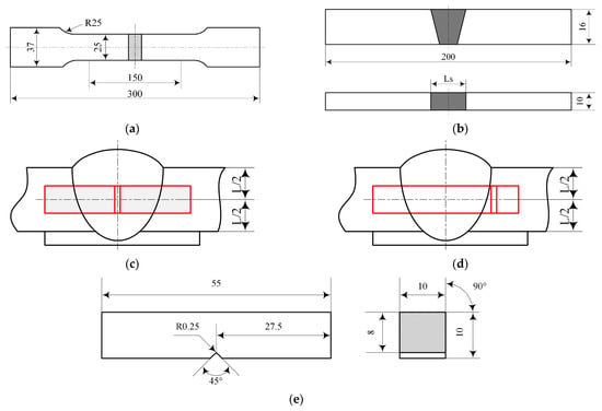
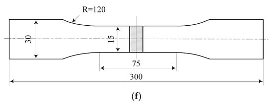
The macroscopic and microscopic inspection of the weld was carried out according to the GB/T 26955-2011 standard. The metallographic specimen was etched by 4% nitric acid alcohol reagent. The etching time was 4–5 s. The macroscopic morphology and microstructure of the joint were observed by a KEYENCEVHX-1000 (Keyence, Osaka, Japan) video microscope and an OLYMPUS-BX51M (Olympus, Tokyo, Japan) metallographic microscope, respectively. The hardness distribution of the joint was measured by an HV-50A (Huayin, Laizhou, China) Vickers hardness tester. According to the relevant provisions of the GB/T 4340.1-2009, three paths of 1 mm from the upper surface, 1 mm from the lower surface, and the center of the plate thickness were tested. The loading load was 10 kgf, and the load holding time was 15 s. Tensile and bending tests were performed using a WDW-300E (SUNS, Shenzhen, China) electronic universal testing machine. The tensile test was carried out according to the relevant provisions of the GB/T 2651-2008 and GB/T 25774.1-2010, and the size of the tensile specimen is shown in Figure 1a. The tensile rate was 3 mm/min. The bending test was carried out according to the relevant provisions of the GB/T 2653-2008 and ISO 5173-2000, and the size of the bending specimen is shown in Figure 1b. The bending rate was 1 mm/min. The bending angle of the bending test was 180°, and the diameter of the indenter was 40 mm. The low temperature (−40 °C) impact test was carried out by using a JB-W300A (Time Test, Jinan, China) Microcomputer controlled pendulum impact tester and a DWY-80A (Time Test, Jinan, China) impact test cryostat. The impact performance test was carried out according to the relevant provisions of the GB/T 2650-2008 and GB/T 229-2007. Notches were opened in the weld and the HAZ (Heat-Affected Zone), respectively, and the sampling positions are shown in Figure 1c,d respectively. The impact sample size is shown in Figure 1e. The impact absorption energy was recorded. The fracture morphology of the sample was observed by a ZEISS SUPRA55 (Zeiss, Oberkochen, German) field emission scanning electron microscope, and the fracture characteristics were analyzed. The fatigue test was carried out by using the QBG-200 (Qianbang, Changchun, China) digital high-frequency fatigue testing machine. The fatigue performance test was carried out according to the relevant provisions of the GB/T 13816-1992, and the sample size is shown in Figure 1f. The stress ratio R = 0, the loading frequency was 130–150 Hz, the stress step was 20 MPa, and the maximum number of cycles was 2 × 10⁶.
3. Results and Analysis
3.1. Macroscopic and Microstructure Morphology
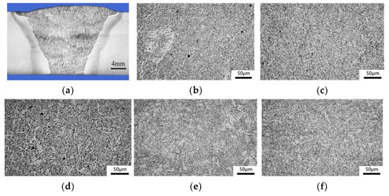
The macroscopic morphology and microstructure characteristics of the cross section of the joint are shown in Figure 1. The cross section of the joint was well formed, and no obvious welding defects were found, as shown in Figure 2a. The microstructure of the cover area was mainly acicular ferrite, with a small amount of proeutectoid ferrite and side plate ferrite. The acicular ferrite was mainly distributed in the grain boundary, and the direction was disordered. The proeutectoid ferrite and side plate ferrite were mainly distributed at the grain boundary, as shown in Figure 2b. The microstructure of the filling zone was mainly acicular ferrite, lamellar ferrite, and a small amount of granular bainite, as shown in Figure 2c. The microstructure of the backing zone was mainly acicular ferrite, lamellar ferrite, and side lath ferrite, as shown in Figure 2d.
Figure 2.
The macro- and micromorphology of the joint: (a) macromorphology; (b) microstructure of the covering surface region; (c) microstructure of the filling region; (d) microstructure of the backing region; (e) microstructure of the coarse-grained region; (f) microstructure of the fine-grained region.
The alloying elements in the weld play an important role in the control of the microstructure. The addition of alloying elements in the E81T1-Ni1M flux-cored wire first reduced the formation of proeutectoid ferrite, and the transformation of austenite to ferrite was delayed. During the cooling process of the joint, the content of the intermediate temperature transformation product in the weld increased, thereby generating more acicular ferrite or bainite structure. Acicular ferrite is a thermodynamic nonequilibrium structure, which is essentially an intragranular nucleation of bainite. The difference between the two is that bainite nucleates at the austenite grain boundary, while acicular ferrite nucleates at the nonmetallic inclusions inside the austenite. The E81T1-Ni1M flux-cored wire contains a suitable proportion of Mn and Si content, which can reduce the continuous-cooling phase transition temperature, refine the structure, and significantly increase the content of acicular ferrite. Acicular ferrite is the most desirable microstructure in the weld. It can effectively improve the strength and toughness of the weld. Its content and morphology determine the impact toughness of the weld. A higher amount of randomly oriented fine AF leads to improving the strength and toughness of the material. The side lath ferrite is a conical or serrated ferrite that extends from the grain boundary to the grain. It is essentially a Widmanstätten structure, which will reduce the performance of the joint. The side lath ferrite also belongs to the proeutectoid ferrite, but the formation temperature is lower than that of the grain boundary ferrite. The appearance of side lath ferrite is mainly due to the high welding heat input and the high air-cooling speed after welding [15].
3.2. Hardness Distribution
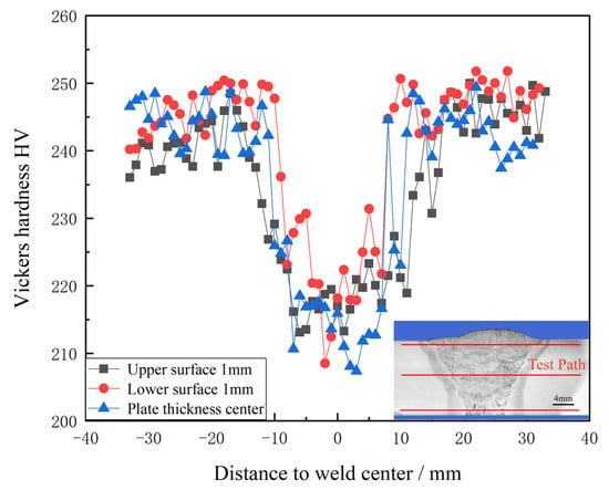
The hardness distribution characteristics of the joint are shown in Figure 3. The results showed that the average hardness of the base metal was about 245 HV, the average hardness of the weld zone was about 215 HV, and the average hardness of the heat-affected zone was about 230 HV. The hardness values of the weld zone and the heat-affected zone were lower than those of the base metal. The hardness value of the weld zone was the lowest, which was the weakest area of the joint. The main reason for the lowest hardness value in the weld zone was that there were more proeutectoid ferrite and lamellar ferrite in the region, and the multipass welding heat effect increased the grain size and further reduced the hardness value. At the same time, the hardness value of the 1 mm area from the lower surface was slightly higher than that of the central area of the plate thickness and the 1 mm area from the upper surface. This was mainly due to the narrow bottom weld, which led to the fast-cooling rate and high temperature gradient in the welding process. The hardness of the heat-affected zone was lower than that of the base metal mainly because the inappropriate welding thermal cycle led to the formation of coarse lath and granular bainite in the heat-affected zone, resulting in softening of the heat-affected zone.
3.3. Mechanical Properties Analysis
3.3.1. Tensile Property
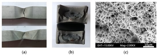
The tensile test results of the joints are shown in Table 4. The test results showed that the average tensile strength of the joint reached 650 MPa, which was about 95% of the tensile strength of the base metal. The average yield strength of the joint was 649 MPa. The average elongation after fracture and the average reduction in the area were about 12% and 43%, respectively. The fracture location and fracture characteristics of the specimen are shown in Figure 4. The tensile specimens were broken in the weld zone, and there was a very obvious necking phenomenon, as shown in Figure 4a. There were no obvious welding defects in the macroscopic fracture, as shown in Figure 4b. The microscopic fracture showed obvious dimple morphology and typical plastic fracture characteristics. There were inclusions of different sizes and quantities at the bottom of the dimples, as shown in Figure 4c. This may be one of the reasons for the close yield strength and tensile strength of the joint. Because the inclusions have a strong influence on the plasticity of the material, there were different degrees of morphological differences and stress concentration in the transverse and longitudinal directions. The cracks competed at the holes of the inclusions, and the cracks first appeared at the positions with a weak bonding force and large stress concentration [16]. This also reduced the plasticity of the joint to a certain extent.
3.3.2. Low-Temperature Impact Properties
The low-temperature (−40 °C) impact test results of the joint are shown in Table 5, and the V-notches were opened in the weld center and the heat-affected zone, respectively. The results showed that the average low-temperature impact energy of the weld zone and the heat-affected zone was 71 J and 253 J, respectively. The low-temperature impact energy of the weld zone was significantly lower than that of the heat-affected zone.
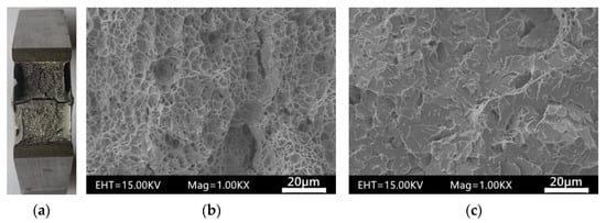
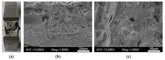
The macroscopic and microscopic fracture characteristics of the V-notch impact specimens at a low temperature in weld zone and the heat-affected zone are shown in Figure 5 and Figure 6. The test results showed that the proportion of the ductile zone of the specimen fracture was small, and the proportion of the cleavage zone was large, whether in the weld zone or in the heat-affected zone, as shown in Figure 5a and Figure 6a. There were obvious dimple morphology characteristics in the ductile area of the fracture of the weld zone and the heat-affected zone, as shown in Figure 5b and Figure 6b. The cleavage zone of the fracture of the weld zone was mainly characterized by dissociation and quasi-cleavage morphology, as shown in Figure 5c. There were some dimple morphology characteristics in the cleavage zone of the fracture of the heat-affected zone, as shown in Figure 6c. The fracture showed the characteristics of a ductile–brittle mixed fracture as a whole. The area of the fracture ductile zone of the V-notch in the heat-affected zone was obviously larger, and there were some characteristics of the dimple in the cleavage zone, which was also one of the reasons why the low-temperature impact energy of the weld zone was lower than that of the heat-affected zone. The structure determined the performance. Because there were more brittle structures, such as the side plate ferrite and flake ferrite, in the weld zone, the toughness of the weld zone was greatly reduced. The lath bainite in the heat-affected zone increased the energy required for crack propagation due to the staggered distribution, which increased the impact energy of the heat-affected zone.
Figure 5.
The fracture morphology of the impact sample of the weld zone: (a) macrofracture; (b) ductile region; (c) cleavage region.
3.3.3. Bending Property
The bending test results of the joints are shown in Table 6. The test results showed that the tensile surface morphology of the bending specimens was good; no obvious cracks were found, and the bending performance of the joints was good.
3.3.4. Fatigue Property
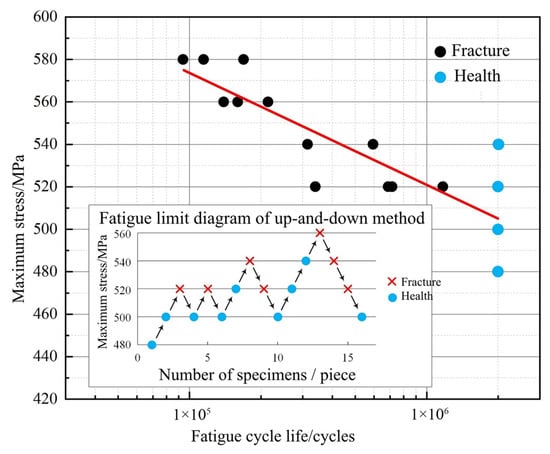
The S-N fatigue curve drawn according to the joint fatigue test results is shown in Figure 7. The median fatigue limit of the 50% survival rate was 520 MPa. The safety fatigue limit of the engineering error δ ≤ 5%, confidence of 95%, and survival rate of 80% was 492 MPa.
The fracture position and fracture morphology of the fatigue specimen are shown in Figure 8. The test results showed that the fatigue specimen cracked in the weld area, and it was located at the bottom weld bead, as shown in Figure 8a. The crack initiation area and crack propagation zone were clearly observed from the macroscopic fracture, as shown in Figure 8b. The fatigue crack initiated near the surface of the specimen, where there were small size inclusions, a loose structure, and a large stress concentration, as shown in Figure 8c, which significantly reduced the fatigue performance of the joint. There were many lamellar structures in the crack propagation zone, as shown in Figure 8d.
Figure 8.
The fracture morphology of the impact sample of the heat-affected zone: (a) macrofracture; (b) ductile region; (c) cleavage region; (d) propagation region.
The surface state and microstructure of the specimen are important factors affecting the fatigue strength. Under cyclic loading, the uneven slip of the metal is mainly concentrated on the surface of the specimen, and fatigue cracks are often generated on the surface; so, the surface state of the specimen has a great influence on the fatigue performance. In this study, the surface of the joint fatigue specimen was smooth after finishing; so, the surface state was not the main factor of fracture.
The staggered distribution of acicular ferrite and granular bainite in the weld can inhibit the formation of grain boundary cracks, improve the slip deformation resistance, inhibit the formation and cracking of the cyclic slip bands, increase the grain boundary resistance of crack propagation, and improve the fatigue strength.
The inclusion has a significant effect on the fatigue strength. The stress concentration at the inclusion is large, and it is often the crack initiation area, which greatly reduces the fatigue performance, reduces the inclusion content; reducing the inclusion size can effectively improve the fatigue strength.
4. Conclusions
The gas-shielded welding of 16 mm thick A710 low-alloy high-strength steel was carried out by using an E81T1-Ni1M flux-cored wire. The microstructure and mechanical properties of the welded joints were systematically studied. The main conclusions are as follows:
(1) The joint was well formed without obvious welding defects. The microstructure of the cover area was mainly acicular ferrite, with a small amount of proeutectoid ferrite and side plate ferrite. The microstructure of the filling zone was mainly acicular ferrite, flaky ferrite, and a small amount of granular bainite. The microstructure of the bottom zone was mainly acicular ferrite, flaky ferrite, and side plate ferrite. The microstructure of the coarse grain zone was mainly lath bainite and granular bainite with coarse grains. The microstructure of the fine grain zone was mainly uniform and fine ferrite and pearlite. The hardness values of the weld zone and the heat-affected zone were lower than that of the base metal, and the hardness value of the weld zone was the lowest, which was the weakest area of the joint.
(2) The average tensile strength of the joint was 650 MPa, which was about 95% of the tensile strength of the base metal. The specimens all fractured in the weld zone, the necking phenomenon was obvious, and the fracture morphology showed typical plastic fracture characteristics. The tensile surface of the bending specimen was smooth, and no obvious cracks were found.
(3) The average low-temperature (−40 °C) impact energy of the weld zone and the heat-affected zone was 71 J and 253 J, respectively. The proportion of the fracture ductile zone was small, and the proportion of the cleavage zone was large. The area of the fracture ductile zone of the heat-affected zone was obviously larger, and the fracture morphology showed the characteristics of a ductile–brittle mixed fracture.
(4) Under the specified life of 2 × 10⁶ cycles, the median fatigue limit of the 50% survival rate was 520 MPa; the safety fatigue limit of the engineering error δ ≤ 5%, confidence of 95%, and survival rate of 80% was about 492 MPa.
Author Contributions
Methodology, Z.Y.; validation, X.W. and L.D.; formal analysis, Z.Y. and X.W.; writing—original draft preparation, X.W.; writing—review and editing, Z.Y.; visualization, Z.Y. All authors have read and agreed to the published version of the manuscript.
Funding
This research received no funding.
Data Availability Statement
Date sharing not applicable.
Conflicts of Interest
The authors declare no conflict of interest.
References
- Rodrigues, T.A.; Duarte, V.; Avila, J.A.; Santos, T.G.; Miranda, R.M.; Oliveira, J.P. Wire and arc additive manufacturing of HSLA steel: Effect of thermal cycles on microstructure and mechanical properties. Addit. Manuf. 2019, 27, 440–450. [Google Scholar] [CrossRef]
- Wang, Z.L. Control of microstructure and properties of welded joints of heavy structures of low alloy high strength steels. Key Eng. Mater. 2019, 814, 171–175. [Google Scholar] [CrossRef]
- Berdnikova, O.; Pozniakov, V.; Bernatskyi, A.; Alekseienko, T.; Sydorets, V. Effect of the structure on the mechanical properties and cracking resistance of welded joints of low-alloyed high-strength steels. Procedia Struct. Integr. 2019, 16, 89–96. [Google Scholar] [CrossRef]
- Zeng, H.L.; Wang, C.J.; Yang, X.M.; Wang, X.S.; Liu, R. Automatic welding technologies for long-distance pipelines by use of all-position self-shielded flux cored wires. Nat. Gas Ind. B 2014, 1, 113–118. [Google Scholar]
- Bracarense, A.Q.; Souza, R.; Costa, M.C.M.; Faria, P.E.; Liu, S. Welding current effect on diffusible hydrogen content in flux cored arc weld metal. J. Braz. Soc. Mech. Sci. Eng. 2002, 24, 278–285. [Google Scholar] [CrossRef]
- Li, Z.; Srivatsan, T.S.; Wang, Y.; Zhang, W.; Li, Y. The spectral analysis of different flux-cored wires during arc welding of metals. Mater. Manuf. Process. 2012, 27, 664–669. [Google Scholar] [CrossRef]
- Hayat, F.; Uzun, H. Microstructural and mechanical properties of dual-phase steels welded using GMAW with solid and flux-cored welding wires. Int. J. Mater. Res. 2012, 103, 828–837. [Google Scholar] [CrossRef]
- Zou, Z.; Liu, Z.; Ai, X.; Wu, D. Effect of aluminum on microstructure and mechanical properties of weld metal of Q960 steel. Crystals 2022, 12, 26. [Google Scholar] [CrossRef]
- Ilić, A.; Miletić, I.; Nikolić, R.R.; Marjanović, V.; Ulewicz, R.; Stojanović, B.; Ivanović, L. Analysis of influence of the welding procedure on impact toughness of welded joints of the high-strength low-alloyed steels. Appl. Sci. 2020, 10, 2205. [Google Scholar] [CrossRef]
- Kornokar, K.; Nematzadeh, F.; Mostaan, H.; Sadeghian, A.; Moradi, M.; Waugh, D.G.; Bodaghi, M. Influence of heat input on microstructure and mechanical properties of gas tungsten arc welded HSLA S500MC steel joints. Metals 2022, 12, 565. [Google Scholar] [CrossRef]
- Oktadinata, H.; Winarto, W.; Siradj, E.S. Microstructure and impact toughness of flux-cored arc welded SM570-TMC steel at low and high heat input. Mater. Sci. Forum 2020, 991, 3–9. [Google Scholar] [CrossRef]
- Ni, Z.; Hu, F.; Li, Y.; Lin, S.; Cai, X. Microstructure and mechanical properties of the ternary gas shielded narrow-gap GMA welded joint of high-strength steel. Crystals 2022, 12, 1566. [Google Scholar] [CrossRef]
- Wen, C.; Wang, Z.; Deng, X.; Wang, G.; Misra, R.D.K. Effect of Heat Input on the Microstructure and Mechanical Properties of Low Alloy Ultra-High Strength Structural Steel Welded Joint. Steel Res. Int. 2018, 89, 1700500. [Google Scholar] [CrossRef]
- Ilić, A.; Ivanović, L.; Josifović, D.; Lazić, V.; Živković, J. Effects of welding on mechanical and microstructural characteristics of high-strength low-alloy steel joints. IOP Conf. Ser. Mater. Sci. Eng. 2018, 393, 012020. [Google Scholar] [CrossRef]
- Song, F.; Yin, C.; Hu, F.; Wu, K. Effects of Mn-depleted zone formation on acicular ferrite transformation in weld metals under high heat input welding. Materials 2022, 15, 8477. [Google Scholar] [CrossRef] [PubMed]
- Atkinson, H.V.; Shi, G. Characterization of Inclusions in Clean Steels: A Review Including the Statistics of Extremes Methods. Prog. Mater. Sci. 2003, 48, 457–520. [Google Scholar] [CrossRef]
Disclaimer/Publisher’s Note: The statements, opinions and data contained in all publications are solely those of the individual author(s) and contributor(s) and not of MDPI and/or the editor(s). MDPI and/or the editor(s) disclaim responsibility for any injury to people or property resulting from any ideas, methods, instructions or products referred to in the content. |
© 2023 by the authors. Licensee MDPI, Basel, Switzerland. This article is an open access article distributed under the terms and conditions of the Creative Commons Attribution (CC BY) license (https://creativecommons.org/licenses/by/4.0/).

