Article

Hydrogen Embrittlement Failure Behavior of Fatigue-Damaged Welded TC4 Alloy Joints

1
State Key Laboratory of Advanced Processing and Recycling of Non-Ferrous Metals, Lanzhou University of Technology, Lanzhou 730050, China
2
Zhejiang E.O. Paton Welding Technology Institute, Hangzhou 311200, China
*
Author to whom correspondence should be addressed.
Crystals 2023, 13(3), 512; https://doi.org/10.3390/cryst13030512
Submission received: 19 February 2023 / Revised: 2 March 2023 / Accepted: 14 March 2023 / Published: 16 March 2023

Abstract

:
The interaction between fatigue damage and hydrogen in TC4 welded joints was analyzed considering specimens with different pre-cycles. The fracture failure caused by hydrogen-induced fatigue damage was investigated using tensile testing and microstructural observations. The results indicate that increasing the number of pre-cycles increases the specimens’ initial dislocation density, enhancing the severity of the hydrogen-induced embrittlement phenomenon. The hydrogen-enhanced local plasticity mechanism, manifested by fracture along the grain boundary, dominates the tensile process in fatigue-damaged hydrogen-filled welded joints after 10,000 and 20,000 pre-cycles. After 30,000 pre-cycles, the hydrogen-enhanced decohesion mechanism dominates the tensile process, manifesting as a transgranular cleavage decoupling fracture.

1. Introduction

TC4 titanium alloys are increasingly used in aerospace, offshore, and petrochemical industries owing to their high strength-to-weight ratio, excellent thermal stability, and corrosion resistance [1,2,3]. However, the inevitable presence of hydrogen atoms in the marine and petrochemical industries has made hydrogen embrittlement a major safety concern for titanium alloys in hydrogen-containing environments [4,5]. Over the last few decades, researchers have proposed several theories to explain the effect of hydrogen on the failure of engineering alloys. These include hydrogen-enhanced local plasticity (HELP) [6,7], hydrogen-enhanced decohesion (HEDE) [8], hydrogen-enhanced strain-induced vacancy [9,10], and adsorption-induced dislocation emission [11] mechanisms. Among them, the HELP and HEDE mechanisms have been increasingly researched. The HEDE model assumes that hydrogen atoms reduce the atomic bond strength of the alloy, lowering the grain boundary or decoupling potential at the decoupling surface. In the HELP mechanism, reducing the interaction of hydrogen with the elastic barrier decreases the shear stress of dislocation movement. However, these theories are not subject to consensus, and hydrogen failure is generally accepted to be the result of multiple mechanisms acting in concert.
Welding is the most common processing method used in the production of complex structural parts of titanium alloys. As titanium is highly active, the welding process is prone to local stress concentrations, inhomogeneities, and inclusions [12,13,14]. Therefore, the integrity of welded joints is crucial for evaluating the quality of structural components [15], and the analysis of resistance to hydrogen embrittlement is a prominent aspect in determining the integrity of welded joints. Previous studies have reported that the effect of hydrogen on welded joints is dependent on the microstructure and type of welded joint area [16,17] and that hydrogen also affects cracking. Hydrogen-induced embrittlement is a critical risk present in the application of titanium alloys [18,19,20]. Titanium alloy components are often subjected to cyclic stresses below the yield strength, and fatigue failure is a significant type of failure observed in welded components [21]. However, unlike the hydrogen embrittlement mechanism that typically occurs under static loading, the role of hydrogen under cyclic dynamic loading becomes unclear and complex [22,23]. As hydrogen is known to accumulate in areas of high stress and strain [24], localized strain zones caused by fatigue loading in the elastic range lead to high concentrations of localized hydrogen in welded joints. This, in turn, is more likely to generate cracks [25]. Additionally, the non-homogeneity of the microstructure in welded joints increases the complexity of the deformation mechanism. Therefore, the interaction between hydrogen and fatigue damage in welded TC4 alloy joints should be systematically analyzed.
The interaction between hydrogen and fatigue damage can be manifested as an effect on the fatigue life of steel [26,27]. Hydrogen atoms can internally diffuse at a faster rate through dislocation migration. Moreover, they tend to concentrate in localized defect areas, such as dislocations, grain boundaries, and semi-coherent phase boundaries [28]. This increases the fragility of defects and causes cracking. The mechanism of the hydrogen effect includes two aspects, namely the hydrogen-induced hardening and softening effects [29,30]. In the hardening effect, hydrogen atoms inhibit the dislocation movement by clustering around dislocations to generate the known Cottrell atmosphere. Furthermore, hydrogen impedes the movement of dislocations by forming hydrogen–vacancy complexes [31]. Conversely, in the softening effect, hydrogen reduces slip resistance and increases dislocation mobility, thereby promoting regions with highly localized plasticity [32]. Hydrogen is known to promote dislocation movement by reducing long-range elastic interactions between dislocations [33]. Consequently, the mechanism of hydrogen action on dislocations remains controversial, and the conclusions are not consistent. This is intrinsically responsible for the complex effects of hydrogen on the fatigue properties of steels and alloys.
Existing research on the structural integrity of welded joints of titanium alloys is primarily focused on the welding process with respect to the tensile properties, fatigue properties, impact toughness, and hydrogen embrittlement sensitivity of welded joints. However, the effect of hydrogen on the mechanical properties of titanium alloy welded joints with fatigue damage has not yet been reported. In this study, we used the TIP-TIG welding method to obtain high-quality welded TC4 alloy joints with a thickness of 20 mm. Furthermore, fatigue-damaged specimens were prepared using a fatigue test machine. The mechanical properties and microstructures of the hydrogenated fatigue-damaged specimens were analyzed, and the failure mechanism of the hydrogen-induced fatigue-damaged welded joints was explored based on the fracture characteristics and microstructural evolution analysis.

2. Material and Methods

2.1. Test Material and Welded Joint Preparation

Welded TC4 alloy joints were prepared using the TIP-TIG welding method based on the multi-layer single-pass welding process, with Ti-6Al-4VA as the filler wire. The weld material was a 20 mm thick TC4 alloy rolled plate with Al and V as the primary added elements; Table 1 presents the complete chemical composition of the test material.
Figure 1a shows the macroscopic shape of the prepared welded joint surface. The joint was designed as a narrow-gap U-shaped bevel to ensure low heat input (Figure 1c). The weld was aesthetically pleasing with a uniform, fine, silvery-white fish-scale pattern. No apparent defects, such as oxidation or edge galling, were observed. Figure 1b depicts the cross-sectional shape of the welded joint. The interface of the weld layer was clear and distinct, and the joint was well formed and over-rounded with the base material.

2.2. Sample Design and Preparation

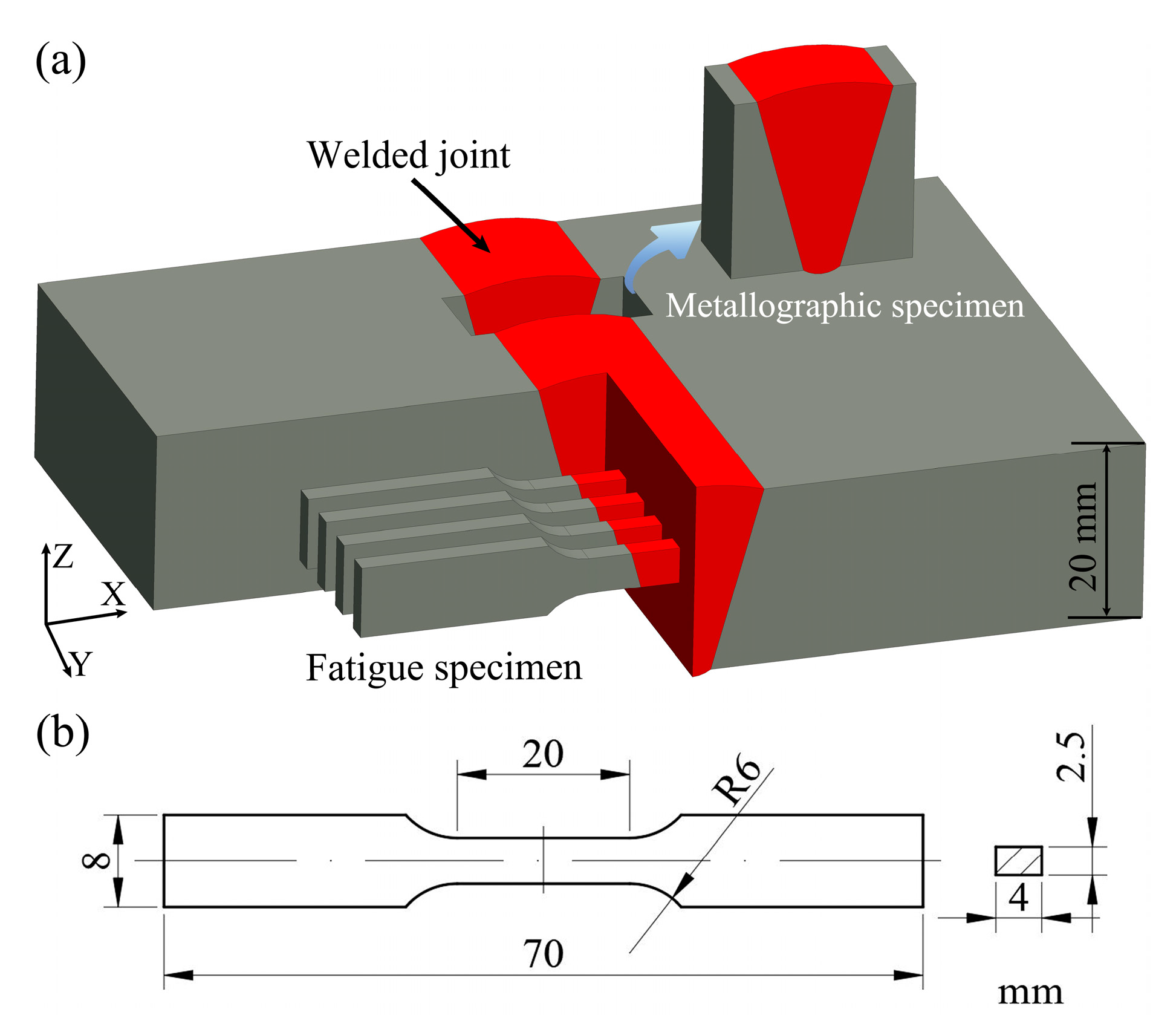
To ensure the reliability and validity of the test results, the fatigue specimens were cut perpendicular to the welded joint. The upper surface of the specimen was parallel to the joint cross-section, and the welded area was contained within the specimen scale distance. All specimens were parallel to each other and were maintained in the same area as the center of the weld. Figure 2a shows the cut sample design of the specimens used for the analysis. Figure 2b illustrates the specimen dimensions used to evaluate the fatigue properties and generate fatigue damage. Fatigue tests were performed using a fatigue tester (Instron 8808) at 25 °C under a constant amplitude tensile load with a stress ratio of R = 0.1. To obtain different levels of fatigue damage, all fatigue specimens were cyclically loaded to a maximum stress of 500 MPa (50% of the yield strength of the welded joint), and the specimens were subjected to 10,000, 20,000, and 30,000 fatigue cycles.

2.3. Cathodic Hydrogen Charging and Tensile Tests

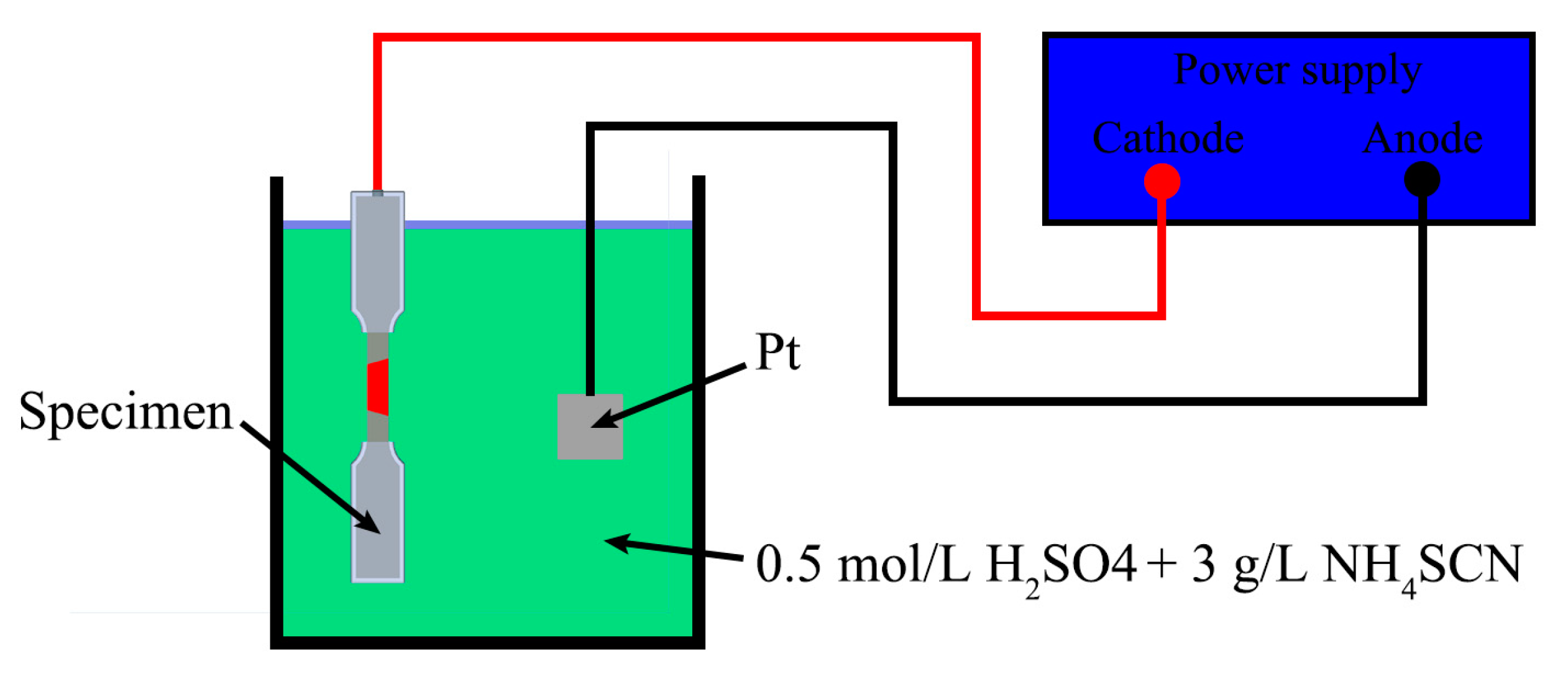
All fatigue-damaged samples were mechanically ground and polished to a grit size of 2000 to remove the surface oxide film. The specimens were then washed with distilled water and ethanol. To prevent oxide film regeneration, the samples were experimentally subjected to 24 h electrochemical hydrogen charging in a 0.5 mol/L H2SO4 + 3 g/L NH4SCN solution at a current density of 50 mA/cm2 immediately after washing [34]. The wire connection and clamping ends of the specimens were sealed with epoxy resin to ensure experimental reliability; only the spar section was exposed to the electrolyte by completely immersing it in the electrolyte during hydrogen charging. Figure 3 depicts the hydrogen-filled system. The tensile properties of the fatigue-damaged specimens with and without hydrogen were obtained using a universal tensile testing machine (AGS-X 300 kN). All tensile tests were performed at a constant strain rate of 0.01 s−1 at 25 °C.

2.4. Microstructural Characterization and Fracture Surface Analysis

The microstructure of the base material (BM) and weld metal (WM) areas were observed using an optical microscope (OM, Axio vert. A1, Zeiss). After mechanical polishing, the metallographic specimens were chemically etched using Kroll’s reagent (95 vol.% H2O, 2 vol.% HNO3, and 3 vol.% HF) for 20 s. Subsequently, the specimens were washed with distilled ethanol and dried. Scanning electron microscopy (SEM, TESCAN MIRA-4) was used to analyze the tensile fracture morphology and microstructure of the specimens with and without hydrogen filling. The samples were characterized using transmission electron microscopy (TEM, JEOL JEM-F200) at 200 kV to investigate the interaction between hydrogen and damage. The mechanism involved in the effect of hydrogen on the tensile properties of fatigue-damaged specimens was examined. TEM foils were prepared using the focused ion beam (FIB, Helios G4 PFIB) lift-out technique with a Ga+ beam source at 30 kV in a dual beam (FEI Helios NanoLab 600). Initially, a platinum-containing layer was deposited on the surface to minimize damage during ion milling. Subsequently, the foils were thinned to approximately 50 nm to generate electron transparency.

3. Results

3.1. Microstructural Analysis

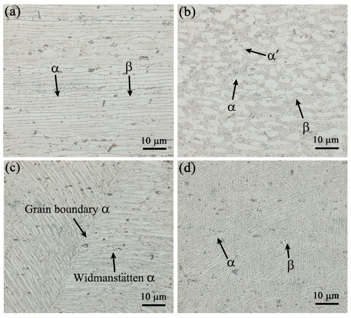
Figure 4a shows the optical microstructure of the welded TC4 alloy joint with the α- and β-phases in the BM region arranged in parallel. Figure 4b indicates that under the influence of the welding thermal cycle, the α-phase was transformed from strip to granular owing to partial tempering in the heat-affected zone (HAZ). Therefore, an isometric and needle-like bimorph organization was observed in the HAZ. The center of the weld exhibited two different tissue distributions, namely the basket mesh and uniform distributions (Figure 4c), with the grain inside the α- and β-phases. A coarse feathery organization comprising the coarse Widmanstätten and grain boundary α-phases appeared at the grain boundaries. This coarse feathery organization was significantly different from the basket mesh organization distribution (Figure 4d), which was attributed to the local accumulation of heat caused by the reciprocal pendulum arc.

3.2. Mechanical Properties

Before testing the fatigue property, the tensile property of the welded joint was tested by tensile test to ensure the rationality of stress setting during the fatigue test. The measured tensile property of the welded joint is shown in Table 2.
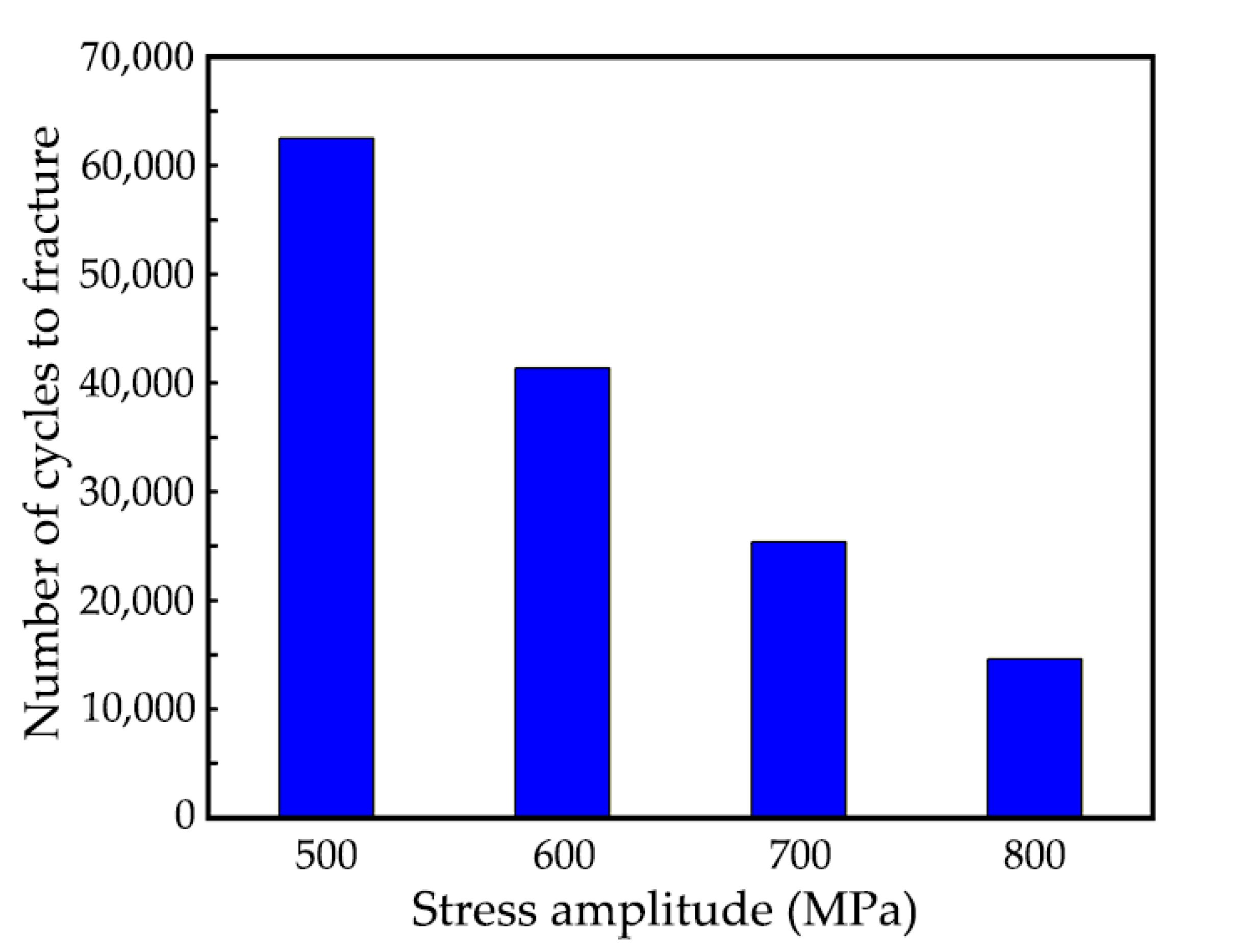
Figure 5 illustrates the results of the high circumference fatigue performance of welded TC4 alloy joints under different stress states. The fatigue performance of the joints gradually decreased with the increase in the applied stress. When the applied stress was 500 MPa (50% of the yield strength), the welded joint exhibited 62,522 cycles to failure fracture. In practice, welded joints are subjected to cyclic stresses substantially lower than 500 MPa. Therefore, the stress intensity of 500 MPa was applied at 10,000, 20,000, and 30,000 cycles to minimize the impact of fatigue damage on mechanical properties. Thus, three groups of fatigue-damaged specimens of welded joints were obtained with different degrees of damage. To ensure the accuracy of the experiment, each group of samples was composed of three parallel samples.
All specimens were fractured at the weld metal during the tensile test. Figure 6 depicts the engineering stress–strain curves of the TC4 welded joints with and without the hydrogen filling at different levels of fatigue damage. We observed that the difference in tensile properties of the welded joints despite the variations in pre-fatigue cycles was not significant in the absence of hydrogen filling. Additionally, the strength of hydrogen-filled welded joints was lower than that of welded joints without hydrogen regardless of the number of loading cycles. However, after 10,000 pre-cycles, the plasticity in the hydrogen-filled fatigue-damaged specimens exhibited nearly no change, whereas, after 20,000 and 30,000 pre-cycles, the plasticity reduced slightly and significantly, respectively. In other words, the increase in the number of fatigue cycles decreased the plasticity of the welded joint after the specimens were filled with hydrogen, whereas the reduction in strength did not follow this rule.

3.3. Fracture Analysis

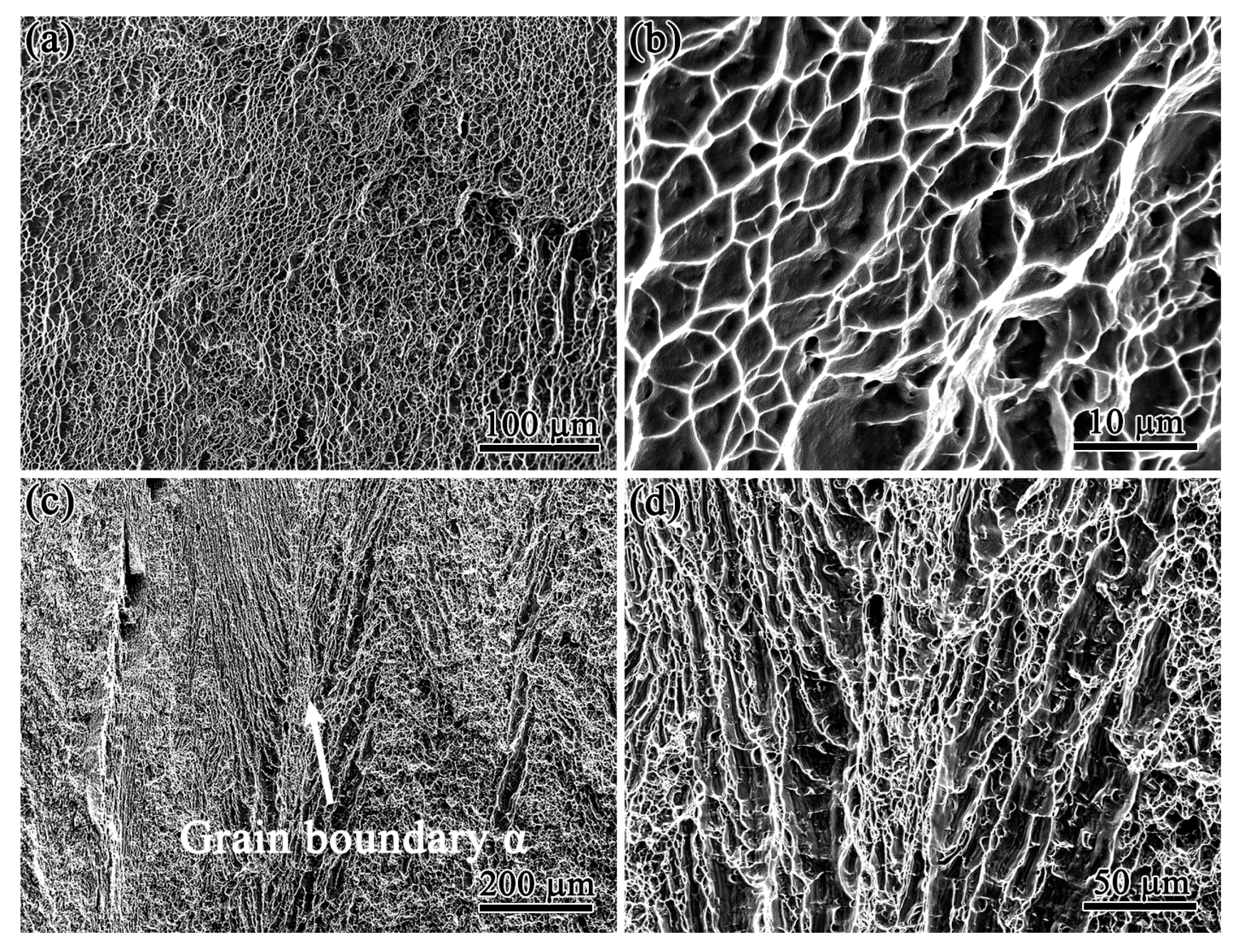
Figure 7, Figure 8 and Figure 9 depict the fracture morphology of the specimens with and without hydrogen filling at 10,000, 20,000, and 30,000 cycles of fatigue damage, respectively. The fracture morphology of the 10,000 pre-cycles specimens without hydrogen exhibited typical toughness fracture characteristics with uniformly distributed tough nests (Figure 7a,b). Similar characteristics of ductile fracture were observed in the specimen after hydrogen charging; however, unlike the fracture of an uncharged specimen, the fracture of the charged specimen exhibited a feathery distribution of tough nests. Figure 7c indicates that the shape of this distribution was identical to that of the feathery grain boundary α-phase (Figure 4c). This implied that cracking occurred along the grain boundary α-phase after hydrogen charging. The high-magnification image (Figure 7d) indicates that the edges of the tough nests were smooth and flat, and the nests were deep.
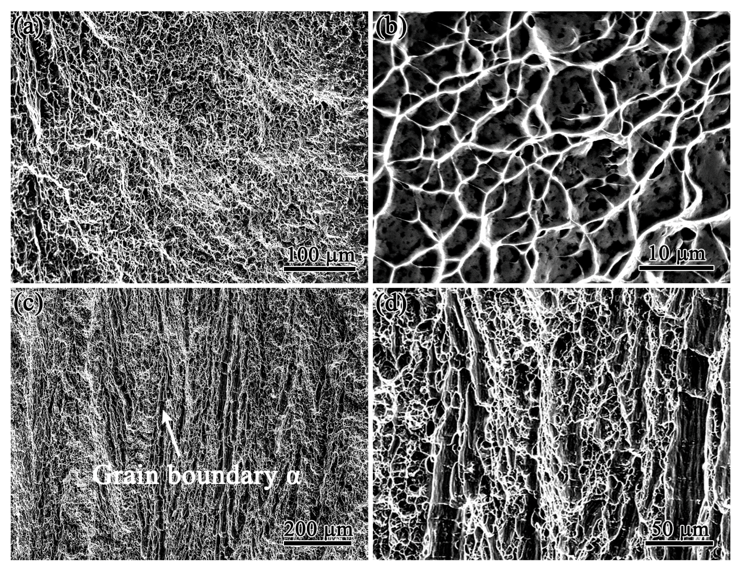
The fatigue-damaged specimens without hydrogen filling continued to exhibit typical ductile fracture after 20,000 pre-cycles. However, the distribution of the tough nests was disorganized compared to that of the specimens subjected to 10,000 pre-cycles (Figure 8a). In comparison with the ligamentous fossa observed in Figure 7b, the fossa in Figure 8b was shallower with a smoother base. The hydrogen-filled specimens exhibited ductile fracture characteristics and a feathery distribution of tough nests after fracture (Figure 8c). However, the signs of a feathery distribution of the tough fossa (Figure 8c) were not as clearly visible as that observed in Figure 7c. The examination of high-magnification images, namely, Figure 7d and Figure 8d, indicated that the ligamentous fossa in the former was shallower and more disorganized than that in the latter.
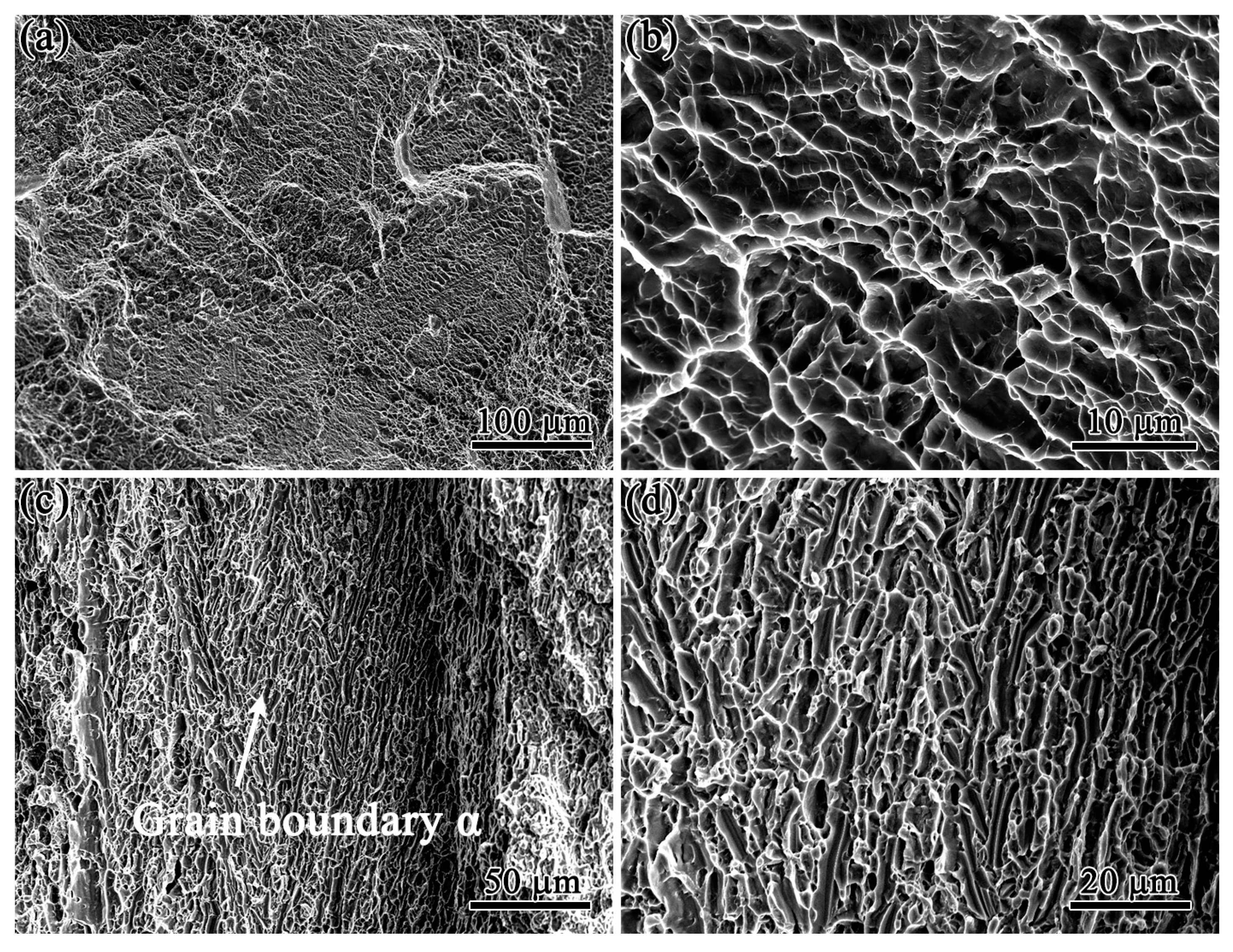
Figure 9 illustrates the fracture morphology of the fatigue-damaged specimens after 30,000 cycles. We observed that the fracture morphology of the uncharged specimen continued to indicate the characteristics of ductile fracture (Figure 9a), whereas the tough nest morphology exhibited a clear difference in comparison with the morphologies of the uncharged specimen subjected to 10,000 and 20,000 cycles; moreover, signs of quasi-dissociative fracture were observed. As indicated in Figure 9b, the tough fossa was extremely shallow under high magnification. Furthermore, an examination of the fracture morphology of the hydrogen-filled specimens exhibited clear quasi-dissolution fracture characteristics after 30,000 pre-cycles (Figure 9d). The fracture continued to exhibit signs of α-phase fracture along the feathery grain boundary (Figure 9c), except the distribution significantly differed from the feathery distribution of the tough fracture morphology observed in the hydrogen-filled specimens subjected to 10,000 and 20,000 pre-cycles.

3.4. Microstructures

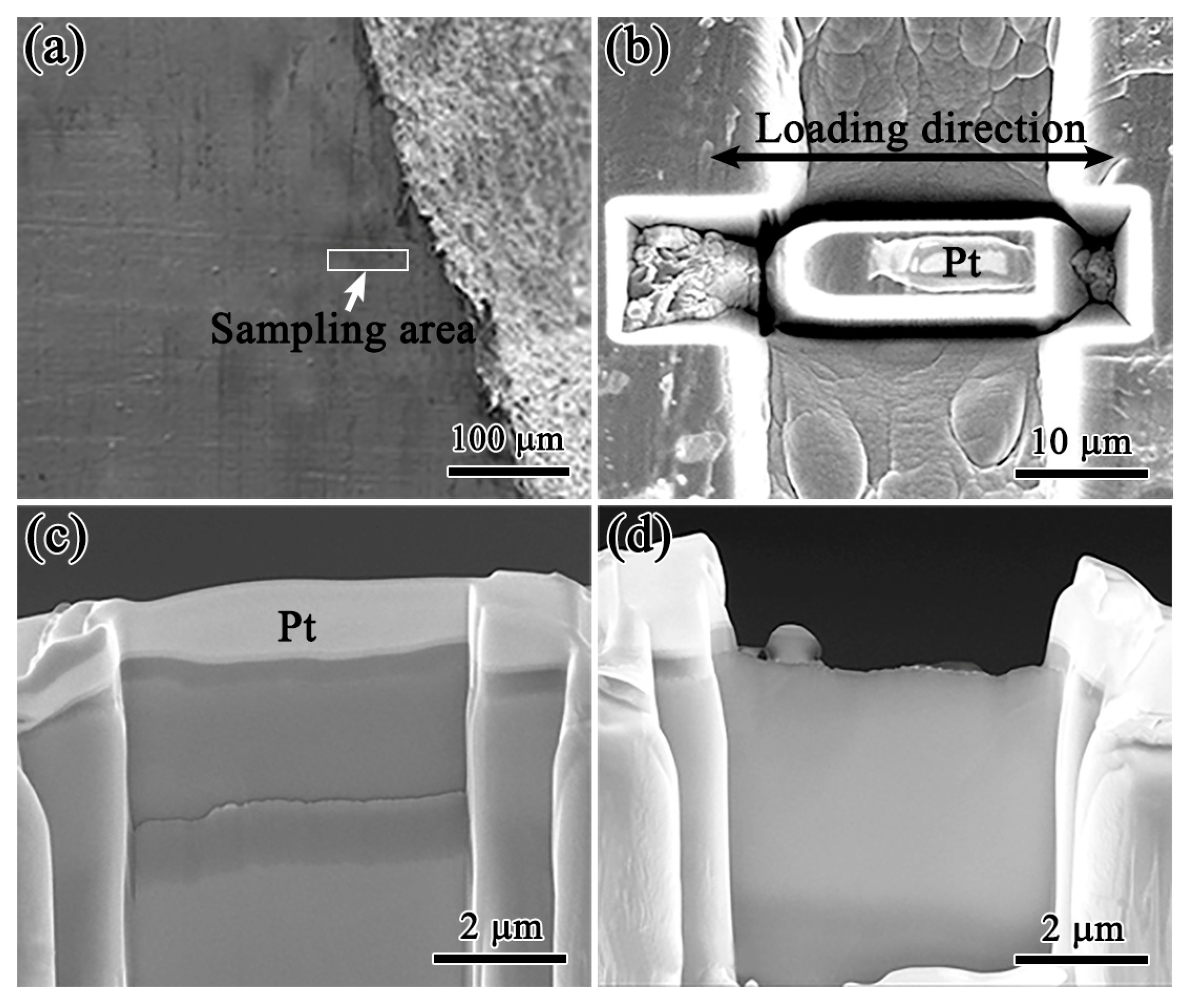
A comparison of the tensile properties and fracture morphology determined that similar results of fatigue damage were observed in the case of both hydrogen-filled and unfilled specimens after 10,000 and 20,000 pre-cycles. However, both types of specimens exhibited significant differences with respect to fatigue damage when subjected to 30,000 pre-cycles. Therefore, to further analyze the reasons for this difference in results under varying pre-cycles, TEM was used to observe the microstructure of fatigue-damaged welded joints considering different pre-cycles. Additionally, the microstructures of fatigue-damaged welded joints with and without hydrogen were examined after a tensile fracture considering 10,000 and 30,000 pre-cycles. Figure 10 shows the process of preparing the TEM specimens using FIB. Initially, an area of interest was selected near the fracture of the specimen (Figure 10a). Subsequently, a Pt layer of 100–200 nm was deposited on the selected surface area using FIB electron beam deposition to protect the crack tip from Ga ion sputtering. Approximately 5 μm deep trigonal notches were then created on either side of the Pt deposited area (Figure 10b). The sheet was cut from the substrate and welded onto the TEM sample grid and thinned to 50 nm using Ga ion sputtering (Figure 10c,d).
Figure 11 shows the microstructure of the fatigue-damaged welded joints considering different pre-cycles. After 10,000 pre-cycles, numerous dislocations were observed in the α-phase. Primarily, linear dislocations and dislocation walls were observed at the interface between the two phases (Figure 11a). After 20,000 pre-cycles, the dislocation walls outside the phase interface thickened, and the dislocations in the α-phase began to entangle (Figure 11b). The microstructure of the specimens after 30,000 pre-cycles exhibited a significant increase in dislocations compared to those observed in the case of 10,000 and 20,000 pre-cycles. Figure 11c indicates that the dislocations in the α-phase were more tightly entangled.
Figure 12 shows the TEM images of fatigue-damaged welded joints with and without hydrogen after tensile fracture when subjected to 10,000 and 30,000 pre-cycles. After 10,000 pre-cycles, unfilled specimens with tensile fracture appeared to comprise numerous dislocations concentrated in the α-phase. Additionally, only a few dislocations were observed in the β-phase, and dislocation build-up was demonstrated in local areas of the α-phase (Figure 12a). The examination of the hydrogen-filled specimens indicated the same concentration of dislocations in the α-phase as that observed in the specimens without hydrogen (Figure 12b). However, several slippages were observed at the interface between the two phases of the hydrogen-filled specimens (Figure 12c), which did not occur in the interior of the two phases. Similar to the samples subjected to 10,000 pre-cycles, the microstructure of the specimens without hydrogen exhibited numerous dislocations after 30,000 pre-cycles; these dislocations were concentrated in the α-phase with only a few in the β-phase. Figure 12e shows the microstructure of the specimen after 30,000 cycles of hydrogen charging. We observed that numerous dislocations appeared in both the α- and β-phases of the specimen, with most of the dislocations accumulating at the phase boundaries. The high-magnification micrograph (Figure 12f) further indicated that hydrogen-filled specimens experienced slip within both phases after 30,000 pre-cycles. The deformation within the α-phase was significantly more severe than that in the β-phase. These phenomena corresponded to those observed in Figure 7, Figure 8 and Figure 9.

4. Discussion

In this study, we investigated the tensile fracture behavior of fatigue-damaged TC4 welded joint specimens subjected to three different pre-cycles considering both hydrogen-filled and unfilled conditions. The mechanism and effect of hydrogen on the tensile properties of welded joints were analyzed considering different degrees of damage. Typically, susceptibility to hydrogen embrittlement is closely associated with the interaction between hydrogen and the trapping sites in the material [35]. Therefore, understanding these interactions can aid in predicting safe conditions of use.
The engineering stress–strain curves of the welded joint specimens without hydrogen were compared considering different pre-cycles. We determined that the difference in tensile properties of the specimens subjected to three different degrees of pre-cycling was not significant; only the strength of the specimens was slightly reduced after 30,000 pre-cycles (Figure 6). SEM analysis of the fracture morphology indicated that specimens subjected to varying pre-cycles exhibited ductile fractures. Although the ductile fossa gradually turned shallow with the increase in the number of cycles, the change was not apparent (Figure 7a, Figure 8a, and Figure 9a); this corresponded to the tensile test results. TEM analysis revealed that the dislocation density in the fatigue-damaged specimens increased with the increase in the number of pre-cycles. Moreover, the dislocation entanglement phenomenon was enhanced (Figure 11). This was because TC4 titanium alloys with different crystal structures in the α- and β-phases exhibited different mechanical properties and were considerably sensitive to slip transfer at the non-co-grained α/β phase interface during plastic deformation. Typically, misalignment between the prismatic α-plane and the adjacent β-plane causes interfacial dislocations with a tendency to nucleate [36]. Therefore, a high degree of mismatch between the two phases during pre-cycling under the influence of cyclic loading led to the accumulation of dislocations at the α/β phase boundary. This accumulation of dislocations increased with the number of cycles. Additionally, as the α-phase of the dense hexagonal structure contained less plastic deformation at room temperature than the β-phase [37], the dislocations were transferred into the α-phase when the number of pre-cycles was increased to 30,000, resulting in entanglement (Figure 11). During the tensile test, dislocations began to slip and interact with each other, increasing the severity of dislocation entanglement in the α-phase. As the number of initial dislocations and dislocation entanglement structures varied between the specimens subjected to different pre-cycles, more dislocation entanglement structures appeared in the α-phase after 30,000 cycles of tensile fracture (Figure 12). At this point, the specimen was plastically deformed, and the dislocation entanglement structure prevented the movement of dislocations. This resulted in localized work hardening to ensure a shallower tensile fracture tough nest compared to that observed in the specimens subjected to 10,000 and 20,000 pre-cycles.
The microstructural analysis revealed that the types of dislocations present in the specimens after different pre-cycles and the location of dislocations differed significantly (Figure 11). Typically, the β-phase, the α/β-phase boundary, and dislocations in duplex titanium alloys are the primary locations for hydrogen capture and the main pathways for hydrogen transport in titanium alloys [38,39]. Therefore, in this study, the effect of hydrogen on the mechanical properties of specimens with different levels of fatigue damage was investigated based on the 24 h electrochemical hydrogen charging of specimens at different levels of pre-cycling. The comparison of the fracture morphologies of the hydrogen-filled specimens (Figure 7, Figure 8 and Figure 9) indicated that the fatigue-damaged specimens from 10,000 and 20,000 pre-cycles exhibited a tough nest-like fracture, indicating apparent signs of plastic deformation and fracture at the feathery grain boundary α. Conversely, after 30,000 pre-cycles, fatigue-damaged specimens exhibited a typical brittle fracture, which occurred as a transganular fracture. This was because the specimens subjected to 10,000 and 20,000 pre-cycles exhibited significant dislocation accumulation only at the α/β phase boundary, with a few dislocations within the α- and-β phases and several at concentrated hydrogen capture sites. After hydrogen charging, hydrogen atoms diffused along the β-phase and α/β phase boundaries to accumulate at the phase boundaries. The hydrogen accumulated at the α/β phase boundaries reduced the resistance to the movement of dislocations, increasing their mobility and serving as carriers of plastic deformation in the metal lattice [40,41]. Consequently, slippage occurred at the phase boundary during stretching (Figure 12c), and nanovoids were created when the stress exceeded the bond strength at the interface. This resulted in crack formation, indicating that the higher the number of phase boundary dislocations, the lower the critical external stress for crack extension. Owing to the large size of the phase boundary near the coarse feathery grain boundary in the α-phase, dislocation generation and hydrogen enrichment were more likely to occur during hydrogen charging. Consequently, the fractures that occurred after the 10,000 and 20,000 pre-cycled specimens were charged with hydrogen, exhibiting the results of fracture along the feathery grain boundary (Figure 7c and Figure 8c); this was dominated by the HELP mechanism.
Specimens subjected to 30,000 pre-cycles exhibited dislocation accumulation at the α/β phase boundary along with dislocation entanglement in both the α- and β-phases. Moreover, severe dislocation entanglement structures within the α-phase provided more favorable locations for hydrogen transport and adsorption. After hydrogen charging, hydrogen was enriched at the α/β phase boundary with a large amount of hydrogen being diffused in the α- and β-phases. A previous study has reported that hydrogen reduces the resistance to dislocation movement and promotes mobility [42], leading to a significant increase in dislocations in both phases. We observed that this in turn resulted in the accumulation of dislocations at the phase boundary (Figure 12e). The HEDE mechanism indicated that when hydrogen atoms surround the material, a certain type of stress acts on the material, causing the hydrogen atoms to diffuse within the material. The interatomic or bond strength of the material was reduced at the crack tip, where the decoupling-like fracture occurred [43]. Therefore, hydrogen simultaneously promoted dislocation movement and reduced the interatomic or bond strength in the α- and β-phases. The reduction in the bond strength decreased the surface energy, which in turn reduced the fracture stress. This implied that fractures were more likely to occur within the phase [44]. As the plasticity of the α-phase was lower than that of the β-phase in the absence of hydrogen action, the α-phase experienced severe hardening after hydrogen filling and deformed less than that observed in the β-phase under tension (Figure 12f). Local plastic enhancement occurred at the α/β phase boundary owing to the presence of dislocation build-up and mismatch gaps. Therefore, the hydrogen-filled specimens subjected to 30,000 pre-cycles fractured, owing to the crystal under tension, and exhibited a disintegrating fracture (Figure 9d).

5. Conclusions

In this study, we analyzed the hydrogen failure mechanism of fatigue-damaged welded TC4 alloy joints considering 10,000, 20,000, and 30,000 pre-cycles. The specimens were subjected to 24 h of electrochemical hydrogen charging, and the failure mechanism was investigated using mechanical tests and microstructural analysis based on SEM and TEM. The results indicated that the number of dislocations increased with the increase in the number of pre-cycles in welded joints. Furthermore, dislocations were first generated and aggregated at the α/β phase boundary when the pre-cycles exceeded a critical value. Subsequently, they were transmitted into the interior of the phase to form a dislocation entanglement structure. However, the difference in performance was not significant even when the specimens were stretched owing to the higher number of pre-cycles. Consequently, the dislocation entanglement area inside the welded joint occurred in the local processing phenomenon, and the fracture tough nest depth gradually became shallower with the increase in the number of pre-cycles. The fatigue-damaged specimens subjected to 10,000 and 20,000 pre-cycles exhibited fewer dislocations, which were concentrated at the α/β phase boundary and certain hydrogen capture sites. The hydrogen at the phase boundary promoted dislocation movement, resulting in local plasticity enhancement at the phase boundary and plastic fracture along the grain. This was attributed to the synergistic effect of the HELP and HEDE mechanisms, with the HELP mechanism being dominant. After 30,000 pre-cycles, dislocation build-up and entanglement occurred both at the phase boundary and within the phase, with more hydrogen capture sites. This, in turn, resulted in local plasticity enhancement at the phase boundary and debonding within the phase, exhibiting penetrating crystalline disintegration fracture. This phenomenon was attributed to the synergistic action of the HELP and HEDE mechanisms, with the HEDE mechanism being dominant.

Author Contributions

X.F.: investigation, data curation, writing—original draft preparation; Y.S.: conceptualization, methodology, project administration, supervision, resources; W.Z.: validation; K.V.: supervision. All authors have read and agreed to the published version of the manuscript.

Funding

This work was supported by the Project of the National Natural Science Foundation of China (grant number 52075235); the Key R&D Program of Gansu Province (grant number 20YF3WA017); and the Young Doctor Program of Education Department of Gansu Province (grant number 2022QB-050).

Data Availability Statement

The raw/processed data required to reproduce these findings cannot be shared at this time, as the data are part of an ongoing study.

Conflicts of Interest

We confirm that the manuscript has been read and approved by all named authors and that there are no other persons who satisfied the criteria for authorship but are not listed. We further confirm that the order of authors presented in the manuscript has been approved by all of us.

References

  1. Banerjee, D.; Williams, J.C. Perspectives on titanium science and technology. Acta Mater. 2013, 61, 844–879. [Google Scholar] [CrossRef]
  2. Wang, X.-Q.; Zhang, Y.-S.; Han, W.-Z. Design of high strength and wear-resistance β-Ti alloy via oxygen-charging. Acta Mater. 2022, 227, 117686. [Google Scholar] [CrossRef]
  3. Hoar, E.; Sahoo, S.; Mahdavi, M.; Liang, S.; Roy, S.; Garmestani, H. Statistical modeling of microstructure evolution in a Ti-6Al-4V alloy during isothermal compression. Acta Mater. 2021, 210, 116827. [Google Scholar] [CrossRef]
  4. Hardie, D.; Charles, E.A.; Lopez, A.H. Hydrogen embrittlement of high strength pipeline steels. Corros. Sci. 2006, 48, 4378–4385. [Google Scholar] [CrossRef]
  5. Bouledroua, O.; Hafsi, Z.; Djukic, M.B.; Elaoud, S. The synergistic effects of hydrogen embrittlement and transient gas flow conditions on integrity assessment of a precracked steel pipeline. Int. J. Hydrogen Energy 2020, 45, 18010–18020. [Google Scholar] [CrossRef]
  6. Wasim, M.; Djukic, M.B.; Ngo, T.D. Influence of hydrogen-enhanced plasticity and decohesion mechanisms of hydrogen embrittlement on the fracture resistance of steel. Eng. Fail. Anal. 2021, 123, 105312. [Google Scholar] [CrossRef]
  7. Nagao, A.; Smith, C.D.; Dadfarnia, M.; Sofronis, P.; Robertson, I.M. The role of hydrogen in hydrogen embrittlement fracture of lath martensitic steel. Acta Mater. 2012, 60, 5182–5189. [Google Scholar] [CrossRef]
  8. Kholtobina, A.S.; Ecker, W.; Pippan, R.; Razumovskiy, V.I. Effect of Alloying Elements on Hydrogen enhanced decohesion in bcc iron. Comput. Mater. Sci. 2021, 188, 110215. [Google Scholar] [CrossRef]
  9. Nagumo, M.; Takai, K. The Predominant role of strain-induced vacancies in hydrogen embrittlement of steels: Overview. Acta Mater. 2019, 165, 722–733. [Google Scholar] [CrossRef]
  10. Takai, K.; Shoda, H.; Suzuki, H.; Nagumo, M. Lattice defects dominating hydrogen-related failure of metals. Acta Mater. 2008, 56, 5158–5167. [Google Scholar] [CrossRef]
  11. Liang, S.; Huang, M.; Zhao, L.; Zhu, Y.; Li, Z. Effect of multiple hydrogen embrittlement mechanisms on crack propagation behavior of FCC metals: Competition vs. Synergy. Int. J. Plast. 2021, 143, 103023. [Google Scholar] [CrossRef]
  12. Li, G.; Chandra, S.; Rahman Rashid, R.A.; Palanisamy, S.; Ding, S. Machinability of additively manufactured titanium alloys: A Comprehensive Review. J. Manuf. Process. 2022, 75, 72–99. [Google Scholar] [CrossRef]
  13. Echlin, M.P.; Stinville, J.C.; Miller, V.M.; Lenthe, W.C.; Pollock, T.M. Incipient slip and long range plastic strain localization in microtextured Ti-6Al-4V titanium. Acta Mater. 2016, 114, 164–175. [Google Scholar] [CrossRef] [Green Version]
  14. Alabort, E.; Kontis, P.; Barba, D.; Dragnevski, K.; Reed, R.C. On the mechanisms of superplasticity in Ti–6Al–4V. Acta Mater. 2016, 105, 449–463. [Google Scholar] [CrossRef] [Green Version]
  15. Panwisawas, C.; Perumal, B.; Ward, R.M.; Turner, N.; Turner, R.P.; Brooks, J.W.; Basoalto, H.C. Keyhole formation and thermal fluid flow-induced porosity during laser fusion welding in titanium alloys: Experimental and modelling. Acta Mater. 2017, 126, 251–263. [Google Scholar] [CrossRef] [Green Version]
  16. Świerczyńska, A.; Fydrych, D.; Landowski, M.; Rogalski, G.; Łabanowski, J. Hydrogen embrittlement of X2CrNiMoCuN25-6-3 super duplex stainless steel welded joints under cathodic protection. Constr. Build. Mater. 2020, 238, 117697. [Google Scholar] [CrossRef]
  17. Świerczyńska, A.; Łabanowski, J.; Michalska, J.; Fydrych, D. Corrosion behavior of hydrogen charged super duplex stainless steel welded joints. Mater. Corros. 2017, 68, 1037–1045. [Google Scholar] [CrossRef]
  18. Balyts’kyi, O.I.; Kostyuk, I.F. Strength of Welded Joints of Cr–Mn Steels with Elevated Content of Nitrogen in Hydrogen-Containing Media. Mater. Sci. 2009, 45, 97–107. [Google Scholar] [CrossRef]
  19. Wang, Q.; Xu, S.; Lecomte, J.-S.; Schuman, C.; Peltier, L.; Shen, X.; Song, W. Crystallographic orientation dependence of hydride precipitation in commercial pure titanium. Acta Mater. 2020, 183, 329–339. [Google Scholar] [CrossRef]
  20. Sinha, V.; Schwarz, R.B.; Mills, M.J.; Williams, J.C. Influence of hydrogen on dwell-fatigue response of near-alpha titanium alloys. Acta Mater. 2020, 188, 315–327. [Google Scholar] [CrossRef]
  21. Ren, D.; Jiang, Y.; Hu, X.; Zhang, X.; Xiang, X.; Huang, K.; Ling, H. Investigation of tensile and high cycle fatigue failure behavior on a TIG welded titanium alloy. Intermetallics 2021, 132, 107115. [Google Scholar] [CrossRef]
  22. Zhao, T.; Liu, Z.; Du, C.; Sun, M.; Li, X. Effects of cathodic polarization on corrosion fatigue life of E690 steel in simulated seawater. Int. J. Fatigue 2018, 110, 105–114. [Google Scholar] [CrossRef]
  23. Zhao, T.; Liu, Z.; Du, C.; Dai, C.; Li, X.; Zhang, B. Corrosion fatigue crack initiation and initial propagation mechanism of E690 steel in simulated seawater. Mater. Sci. Eng. A 2017, 708, 181–192. [Google Scholar] [CrossRef]
  24. Alvaro, A.; Olden, V.; Akselsen, O.M. 3D Cohesive modelling of hydrogen embrittlement in the heat affected zone of an X70 pipeline steel. Int. J. Hydrogen Energy 2013, 38, 7539–7549. [Google Scholar] [CrossRef]
  25. Gaddam, R.; Pederson, R.; Hörnqvist, M.; Antti, M.-L. Influence of hydrogen environment on fatigue crack growth in forged Ti-6Al-4V: Fractographic analysis. IOP Conf. Ser. Mater. Sci. Eng. 2013, 48, 012010. [Google Scholar] [CrossRef] [Green Version]
  26. Murakami, Y.; Matsunaga, H. The effect of hydrogen on fatigue properties of steels used for fuel cell system. Int. J. Fatigue 2006, 28, 1509–1520. [Google Scholar] [CrossRef]
  27. Tao, J.; Hu, S.; Ji, L. Effect of trace solute hydrogen on the fatigue life of electron beam welded Ti-6Al-4V alloy joints. Mater. Sci. Eng. A 2017, 684, 542–551. [Google Scholar] [CrossRef]
  28. Flis, J.; Ashok, S.; Stoloff, N.S.; Duquette, D.J. Hydrogen embrittlement of amorphous alloys based on iron and nickel. Acta Metall. 1987, 35, 2071–2079. [Google Scholar] [CrossRef]
  29. Zhao, Y.; Seok, M.-Y.; Choi, I.-C.; Lee, Y.-H.; Park, S.-J.; Ramamurty, U.; Suh, J.-Y.; Jang, J. The role of hydrogen in hardening/softening steel: Influence of the charging process. Scr. Mater. 2015, 107, 46–49. [Google Scholar] [CrossRef]
  30. Miresmaeili, R.; Liu, L.; Kanayama, H. A Possible Explanation for the contradictory results of hydrogen effects on macroscopic deformation. Int. J. Press. Vessel. Pip. 2012, 99–100, 34–43. [Google Scholar] [CrossRef]
  31. Li, S.; Li, Y.; Lo, Y.-C.; Neeraj, T.; Srinivasan, R.; Ding, X.; Sun, J.; Qi, L.; Gumbsch, P.; Li, J. The interaction of dislocations and hydrogen-vacancy complexes and its importance for deformation-induced proto nano-voids formation in α-Fe. Int. J. Plast. 2015, 74, 175–191. [Google Scholar] [CrossRef]
  32. Sirois, E.; Birnbaum, H.K. Effects of hydrogen and carbon on thermally activated deformation in nickel. Acta Metall. Mater. 1992, 40, 1377–1385. [Google Scholar] [CrossRef]
  33. Robertson, I.M.; Sofronis, P.; Nagao, A.; Martin, M.L.; Wang, S.; Gross, D.W.; Nygren, K.E. Hydrogen embrittlement understood. Metall. Mater. Trans. A 2015, 46, 2323–2341. [Google Scholar] [CrossRef] [Green Version]
  34. Ohaeri, E.; Eduok, U.; Szpunar, J. Relationship between microstructural features in pipeline steel and hydrogen assisted degradation. Eng. Fail. Anal. 2019, 96, 496–507. [Google Scholar] [CrossRef]
  35. Metalnikov, P.; Eliezer, D.; Ben-Hamu, G. Hydrogen trapping in additive manufactured Ti–6Al–4V alloy. Mater. Sci. Eng. A 2021, 811, 141050. [Google Scholar] [CrossRef]
  36. Kong, D.; Zhao, D.; Zhu, G.; Ni, X.; Zhang, L.; Wu, W.; Man, C.; Zhou, Y.; Dong, C.; Sun, B. Heat treatment effects on the hydrogen embrittlement of Ti6Al4V fabricated by laser beam powder bed fusion. Addit. Manuf. 2022, 50, 102580. [Google Scholar] [CrossRef]
  37. Benmessaoud, F.; Cheikh, M.; Velay, V.; Vidal, V.; Matsumoto, H. Role of grain size and crystallographic texture on tensile behavior induced by sliding mechanism in Ti-6Al-4V alloy. Mater. Sci. Eng. A 2020, 774, 138835. [Google Scholar] [CrossRef]
  38. Kim, J.; Plancher, E.; Tasan, C.C. Hydrogenation-induced lattice expansion and its effects on hydrogen diffusion and damage in Ti–6Al–4V. Acta Mater. 2020, 188, 686–696. [Google Scholar] [CrossRef]
  39. Takasawa, K.; Ikeda, R.; Ishikawa, N.; Ishigaki, R. Effects of grain size and dislocation density on the susceptibility to high-pressure hydrogen environment embrittlement of high-strength low-alloy steels. Int. J. Hydrogen Energy 2012, 37, 2669–2675. [Google Scholar] [CrossRef]
  40. Kappes, M.; Iannuzzi, M.; Carranza, R.M. Hydrogen embrittlement of magnesium and magnesium alloys: A Review. J. Electrochem. Soc. 2013, 160, C168–C178. [Google Scholar] [CrossRef]
  41. Laptev, R.; Kudiiarov, V.; Pushilina, N. Hydrogen influence on defect structure and mechanical properties of EBM Ti-6Al-4V. Mater. Today Proc. 2019, 19, 2084–2088. [Google Scholar] [CrossRef]
  42. Martin, M.L.; Somerday, B.P.; Ritchie, R.O.; Sofronis, P.; Robertson, I.M. Hydrogen-induced intergranular failure in nickel revisited. Acta Mater. 2012, 60, 2739–2745. [Google Scholar] [CrossRef]
  43. Dwivedi, S.K.; Vishwakarma, M. Hydrogen embrittlement in different materials: A review. Int. J. Hydrogen Energy 2018, 43, 21603–21616. [Google Scholar] [CrossRef]
  44. Djukic, M.B.; Bakic, G.M.; Sijacki Zeravcic, V.; Sedmak, A.; Rajicic, B. The synergistic action and interplay of hydrogen embrittlement mechanisms in steels and iron: Localized plasticity and decohesion. Eng. Fract. Mech. 2019, 216, 106528. [Google Scholar] [CrossRef]
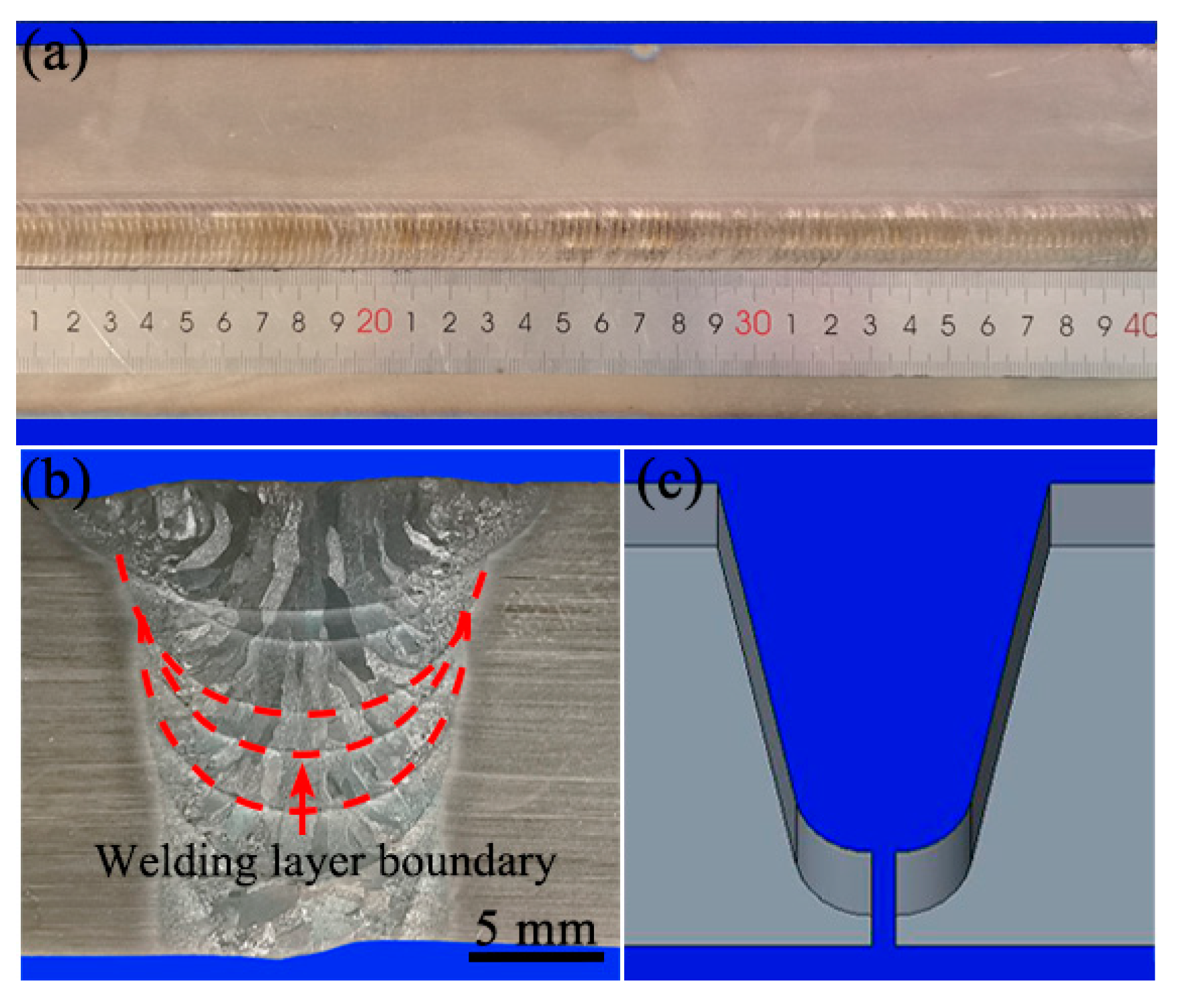
Figure 1. Macro-morphology of the welded joint: (a) surface morphology, (b) section morphology, and (c) welding groove.
Crystals 13 00512 g001
Figure 2. Test specimen of (a) the cut sample design and (b) the corresponding dimensions.
Crystals 13 00512 g002
Figure 3. Schematic of the hydrogen charging system.
Crystals 13 00512 g003
Figure 4. Microstructures of the (a) BM, (b) HAZ, and (c,d) fusion zone (FZ).
Crystals 13 00512 g004
Figure 5. High cycle fatigue properties of welded TC4 alloy joints under different stress states.
Crystals 13 00512 g005
Figure 6. Engineering stress–strain curves of the TC4 welded joints with and without hydrogen filling at varying levels of fatigue damage.
Crystals 13 00512 g006
Figure 7. Fracture morphology of the fatigue-damaged samples after 10,000 pre-cycles: (a) Low-power and (b) high-magnification images of the H-charged sample. (c) Low-power and (d) high-magnification images of uncharged samples.
Crystals 13 00512 g007
Figure 8. Fracture morphology of the fatigue-damaged samples after 20,000 pre-cycles: (a) Low-power and (b) high-magnification images of the H-charged sample. (c) Low-power and (d) high-magnification images of uncharged samples.
Crystals 13 00512 g008
Figure 9. Fracture morphology of the fatigue-damaged samples after 30,000 pre-cycles: (a) Low-power and (b) high-magnification images of the H-charged sample. (c) Low-power and (d) high-magnification images of uncharged samples.
Crystals 13 00512 g009
Figure 10. Preparation of TEM samples using FIB: (a) determination of cutting position, (b) sample cutting, and (c,d) sample reduction.
Crystals 13 00512 g010
Figure 11. TEM images of the TC4 welded joint after (a) 10,000, (b) 20,000, and (c) 30,000 cycles.
Crystals 13 00512 g011
Figure 12. TEM images of the TC4 welded joint after the tensile fracture: (a) Uncharged sample after 10,000 cycles. (b) H-charged sample after 10,000 cycles. (c) Enlarged view of the area within the red wireframe in (b). (d) Uncharged sample after 30,000 cycles. (e,f) H-charged sample after 30,000 cycles.
Crystals 13 00512 g012
Table 1. Chemical composition (wt.%) of the Ti-6Al-4V alloy.
TiAlVFeCNHO
Bal.6.254.050.200.010.010.0010.12
Table 2. Tensile properties of welded joints.
SampleTensile Strength (MPa)Yield Strength (MPa)
Welded joint1063.4944.0
Disclaimer/Publisher’s Note: The statements, opinions and data contained in all publications are solely those of the individual author(s) and contributor(s) and not of MDPI and/or the editor(s). MDPI and/or the editor(s) disclaim responsibility for any injury to people or property resulting from any ideas, methods, instructions or products referred to in the content.