Abstract
In this experiment, we investigated the effects of different reactions on the growth process and morphology of h-MoO3 and α-MoO3, and their optical properties and photocatalytic activities were also investigated. Orthogonal experiments were designed to investigate the effects of four influencing factors, namely the amount of ammonium molybdate tetrahydrate (AHM), the type of acid, the reaction temperature and the holding time, on the morphology of h-MoO3 by a microwave hydrothermal method. The phase and morphology were analyzed by using advanced physicochemical techniques. The XRD results showed that the samples produced by the microwave hydrothermal method had sharp diffraction peaks, high crystallinity and complete crystalline shape. AHM generates h-MoO3 in both hydrochloric and nitric acid environments. In particular, when the temperature rises to 200 °C, the generated h-MoO3 will be converted to α-MoO3 in a nitric acid environment, which will be generated in a sulfuric acid environment. Therefore, increasing the reaction temperature will result in the conversion of h-MoO3 to α-MoO3 in sulfuric acid solution. SEM results show that the sample prepared from hydrochloric acid solution has a complete hexagonal prism morphology, while the sample prepared from sulfuric acid solution presents a long fibrous morphology, and the sample prepared from nitric acid solution has many defects on the surface of the hexagonal prism morphology. Interestingly, sample A11 prepared in nitric acid solution showed a spherical structure. Since the generated A3, A6 and A9 samples are all stable phase α-MoO3, they have a wider band gap compared with other samples. Their particle size is up to the nanometer scale, so they have strong adsorption properties. The spherical sample A11 has excellent adsorption and photocatalytic activity.
1. Introduction
With the large-scale expansion of industry and the continuous development of cities, the pollution problem has become more and more serious and, especially, water pollution has caused serious adverse consequences and destroyed the ecological balance [1,2,3]. MoO3 has excellent adsorption performance and excellent photocatalytic activity, so it has a promising application prospect in the treatment of water pollution [4,5,6]. MoO3 has a different morphology depending on the preparation process, is soluble in alkalis and only reacts with strong acids to form white precipitates of molybdic acid. MoO3 is a semiconductor material with a band width that varies depending on the crystalline form, ranging from 2.5 to 3.2 eV [7]. The crystalline forms can be divided into three types [8,9,10,11], namely thermodynamically stable orthorhombic phase α-MoO3, metastable phase monoclinic phase β-MoO3 and hexagonal phase h-MoO3. The [MoO6] octahedral structure is the basic unit of MoO3 in which Mo atoms occupy the center of an octahedron and O atoms occupy the six top corners of the octahedron. In metastable phase h-MoO3, the octahedral structural units share O in the top corners along the Z-axis to form a chain structure, and the different chains form a hexagonal symmetric structure with adjacent O atom connections [12]. Since the metastable phase h-MoO3 has special ion channels [13], it has a wide range of applications in batteries, gas sensing, photocatalysis and adsorption. Yongfang Niu used a hydrothermal method to prepare h-MoO3. The reaction precursor AHM was dissolved completely in 50 mL distilled water, which was placed into a reactor at 200 °C for 20 h. The specific surface area of the prepared h-MoO3 reached 149.3 m2/g, and the specific capacitance of the material reached 229 F/g under a charge/discharge current of 0.2 A/g [14]. MoO3 in 2D nanosheets has a good response ability to H2S, mainly because Mo atoms around the void break through the shielding effect of the O atom layer, showing a better adsorption effect on H2S and O2 molecules [15]. Zhengqing Cai used co-precipitation to synthesize AgBr/h-MoO3 composite photocatalyst with AHM as the precursor. Specifically, hexagonal prism h-MoO3 was synthesized successfully by a hydrothermal method at 120 °C for 24 h. NaBr and AgNO3 were added dropwise to the suspension of h-MoO3, in which AgBr was precipitated on the surface of h-MoO3, forming Z-type heterojunctions to improve the photocatalytic reaction efficiency. The degradation rate of AgBr/h-MoO3 to TMP reached 97% in 20 min [16]. The mixed phase h-MoO3/α-MoO3 has great potential in water pollution control because of its high surface charge and large surface area [17]. At present, the main method to prepare h-MoO3 is the hydrothermal method, which can generate h-MoO3 with different morphologies by controlling different reaction conditions. The ordinary hydrothermal nanosheet h-MoO3 has a large specific surface area, and its adsorption capacity of rhodamine B (RhB) and methylene blue (MB) can reach 1242 and 1433 mg/g [6]; Bhagyashri B Kamble used a sol hydrothermal method to synthesize h-MoO3. A 0.05 M AHM solution was mixed with distilled water in a ratio of 1:1, then 0.5 mL nitric acid was dropped into the mixture to obtain a 20 mL acidified mixture. The acidified mixture was poured into a polyethylene reactor for 20 min and held at 180 °C for 8 h, then was washed, dried and annealed at 350 °C for 2 h to obtain hollow prisms of h-MoO3 [18]. Due to the unique crystal structure and hexagonal prism shape of h-MoO3, a composite with h-MoO3 as the base material is widely used. h-MoO3, which is rich in O vacancies, has good electrical conductivity and electrocatalytic performance as a catalyst for cathode material [19]. The morphology of h-MoO3 has a great influence on the overall performance of the material, therefore it is crucial to investigate the influence of the experimental conditions on the morphology of h-MoO3. In this study, AHM was used as the precursor, and the pH was adjusted by dropping hydrochloric acid, nitric acid and sulfuric acid. The complete hexagonal prism h-MoO3 was synthesized by the microwave hydrothermal method, and its growth mechanism was further elaborated. A novel spherical structure h-MoO3 was prepared by adjusting the reaction conditions. The appearance of the spherical structure h-MoO3 significantly improved the adsorption and photocatalytic properties of h-MoO3. Compared with other photocatalytic materials such as hexaferrite materials, MOFs [20], etc., it also has certain advantages. The sample preparation is simple and the raw material price is low. Large area has a high economic advantage, and the experimental sample has a larger band gap, so the ability to degrade pollutants is stronger. As the A11 sample has strong adsorption properties, water pollution can be treated by adsorption properties under no light conditions.
2. Materials and Methods
2.1. Materials
Ammonium heptamolybdate ((NH4)6Mo7O24·4H2O, AHM), concentric nitric acid (HNO3), hydrochloric acid (HCl), sulfuric acid (H2SO4), deionized water (H2O), ethanol (C2H5OH) and methylene blue (MB) were purchased from Sinopharm Group Chemical Reagent, and the reagents were used without further purification.
2.2. Sample Preparation
The effect on the morphology of h-MoO3 was investigated by orthogonal experiments adjusting the amount of AHM, the type of acid, the experimental temperature and the reaction time. The orthogonal factor levels of h-MoO3 synthesis are shown in Table 1, and the orthogonal experiment table is shown in Table 2.

Table 1.
Level table of orthogonal factors.
Table 2.
Orthogonal test table L9 (34).
A quantity of ammonium heptamolybdate ((NH4)6Mo7O24·4H2O, AHM) was weighed according to the experimental Table 1, Table 2, Table 3 and Table 4 and dissolved in 30 mL of distilled water, then 10 mL of acid solution was added dropwise and mixed to uniformity for 12 h with magnetic stirring. The solution was poured into a 100 mL microwave hydrothermal reactor for microwave heating. After the reaction, the precipitation in the solution was centrifuged and cleaned several times until the supernatant pH = 7, and then put into the drying oven to dry at 80 °C for 10 h.
Table 3.
Batch formulas of the samples of A10 and A11.
Table 4.
Band gap, degradation rate, rate constant and R2 of the samples.
On the basis of the above experiments, the following experimental scheme for the preparation of spherical h-MoO3 is described in this paper. The experimental formulations are shown in Table 3.
The experimental procedure is the same as for A1.
2.3. Characterization
The crystal structure of the samples was analyzed by the D/max-ⅢA transtarget X-ray diffractometer produced by Niko Electric Co., LTD. The test conditions were as follows: Cu target, scanning form was step scanning, step length was 0.02°, working voltage was 40 kV, working current was 30 mA, scanning range was 5°~80°. A scanning electron microscope (JSM-5610LV) was used to observe the morphology of the samples. The test conditions were as follows: acceleration voltage 0.5~30 kV, low vacuum degree 1~270 Pa. The diffuse reflectance spectra of the samples were measured by a UV–visible diffuse reflectance spectrophotometer (UV-3600) produced in Shimadzu of Japan. The test range was 220–1200 nm. BET surface areas of samples were measured by an automatic surface area and porosity analyzer (TriStarll3020) produced in Mack instrument of the United States.
2.4. Evaluation of Photocatalytic Activity
The photocatalytic degradation test was carried out in a reactor made by Wuhan University of Technology. The initial concentration of the methylene blue (MB) solution was 20 mg/L, and the pH of the solution was controlled at about 6.5. First, 0.1g sample powder was added to the MB solution, and the solution was dispersed by magnetic stirring for 30 min to achieve adsorption equilibrium in a dark environment. The distance of the UV lamp from the liquid surface was fixed at 15 cm. The stability of the solution was maintained at 25 °C. A UV lamp with a main wavelength of 253.7 nm was used as the light source. A sample was taken every 30 min, and the absorption spectrum of the solution in the wavelength range of 200–800 nm was measured by a Beijing Rayleigh UV-1601 ultraviolet spectrophotometer. The absorbance at the maximum absorption peak of 664 nm (the main absorption peak of MB) in the absorption spectrum was selected to calculate the degradation rate of MB solution by the sample photocatalyst. According to the Beer–Lambert–Bouguer law, there is a good linear relationship between solution concentration and absorbance at a low concentration. Therefore, the change in the relative absorbance value can be used to characterize the change in MB concentration in the degradation process. The degradation rate η was (1). The photocatalytic reaction process is generally described by the Langmuir–Hinshelwood (L-H) Equation (2).
3. Results and Discussion
3.1. Phase Composition Analysis
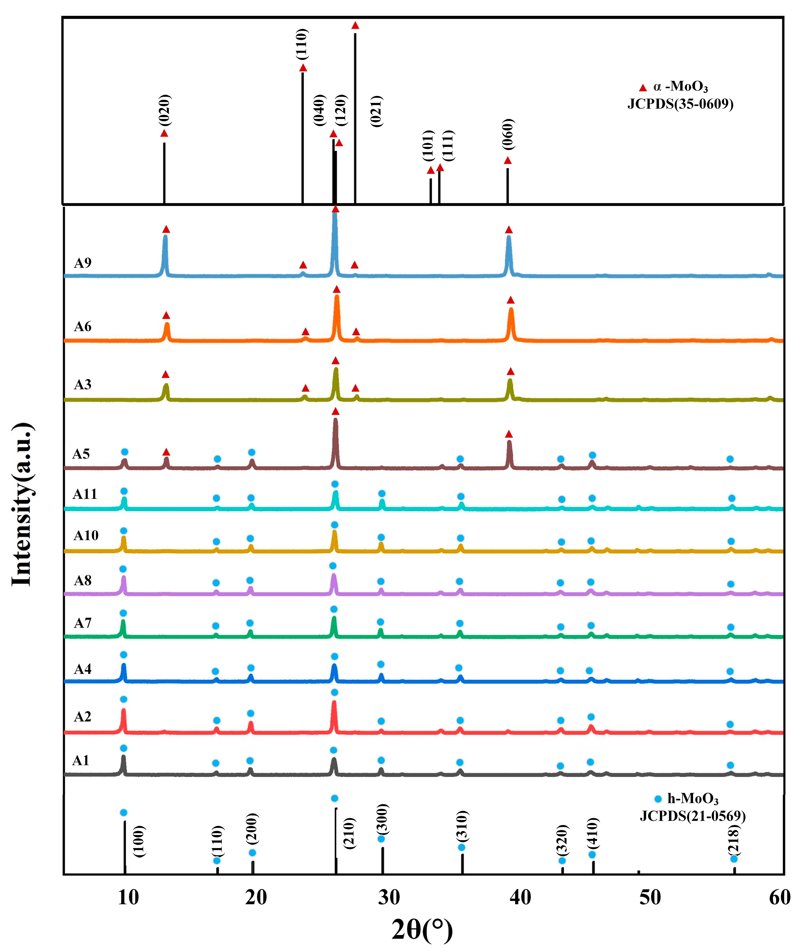
Figure 1 shows the XRD patterns of the A series samples, from which it can be observed that the main diffraction peaks in the spectra of samples A1, A2, A4, A6, A8, A10 and A11 all appear at 2θ = 9.7°, 19.5°, 25.8°, 29.4°, 35.5° and 45.5°, in agreement with the data from the standard JCPSD card (21-0569) [21], corresponding to h-MoO3 (020), (110), (040), (300), (310) and (410) diffraction peaks on the crystallographic planes. XRD analysis showed that the prepared samples were h-MoO3. Samples have no other spurious peaks and intense diffraction peaks, which showed that samples were pure phase and had a highly crystalline structure. The main diffraction peaks of samples A3, A6 and A9 were at position 2θ = 12.8°, 23.3°, 25.7°, 25.9°, 27.3°, 33.1°, 33.8° and 39.0° representing the (100), (200), (210), (120), (021), (101), (111), (060) crystallographic planes of α-MoO3 [22], respectively. In particular, sample A5 had both the diffraction peak of h-MoO3 and the diffraction peak of α-MoO3, which indicates that h-MoO3 was converted into α-MoO3 in the high-temperature environment. This is mainly because α-MoO3 is a high-temperature stable phase, and when the reaction temperature reaches 200 °C, NH4+ in the h-MoO3 ion channel will escape due to violent Brownian motion, resulting in its loss of support and crystal transformation.
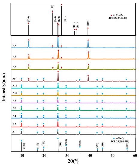
Figure 1.
XRD patterns of samples A1–A11.
3.2. SEM Morphology Study
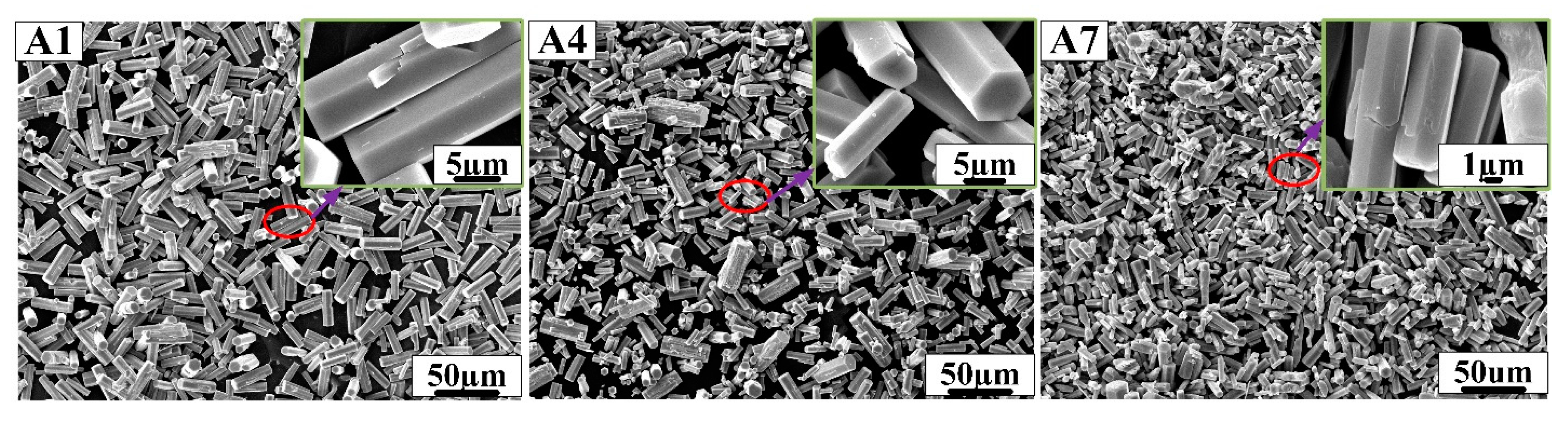
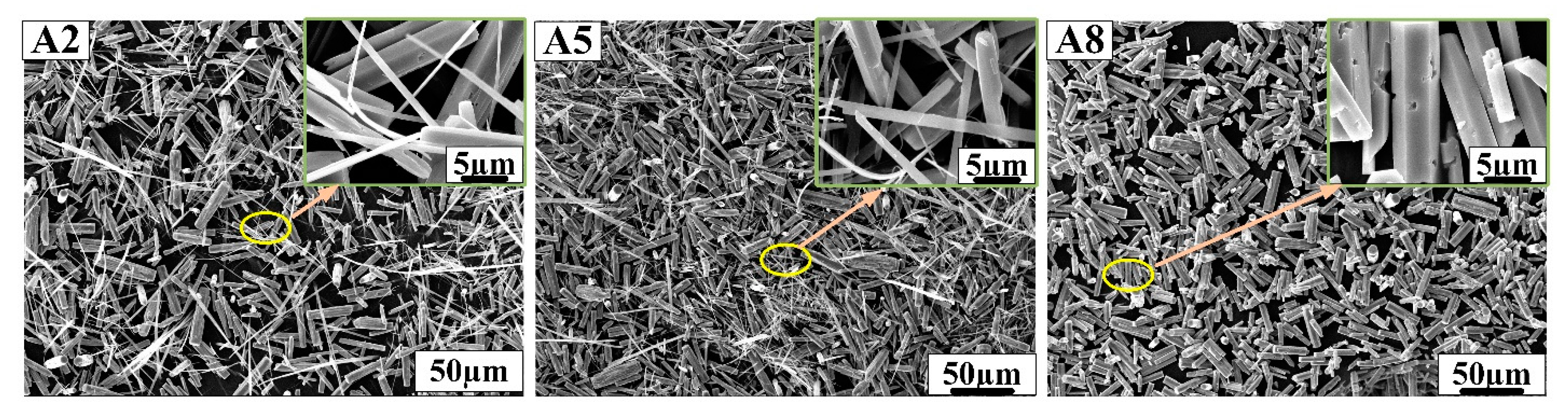
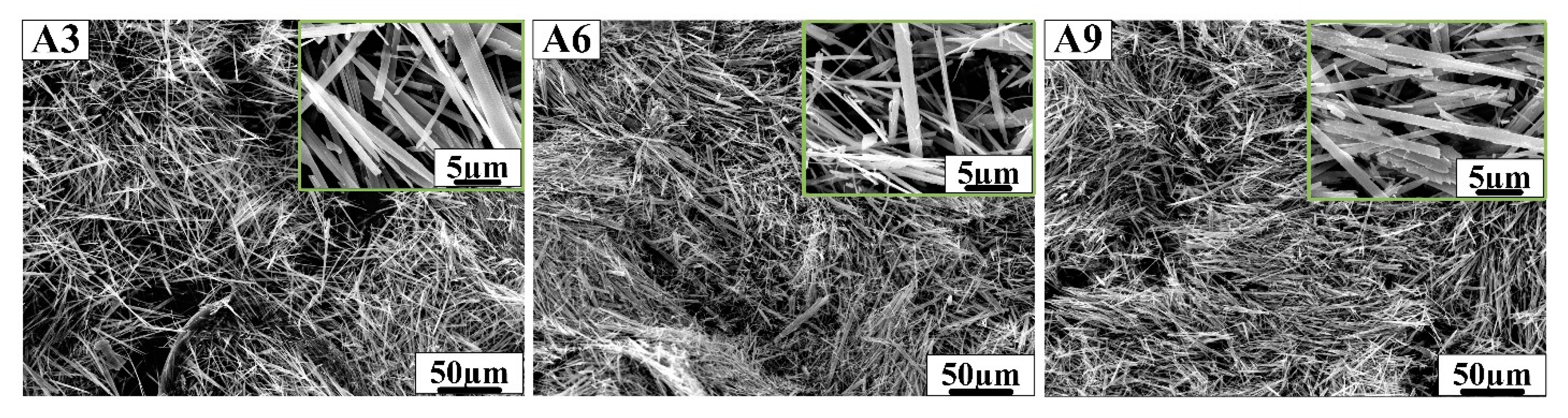
Figure 2 shows the SEM profile of samples prepared in hydrochloric acid solution, Figure 3 shows the SEM profile of samples prepared in nitric acid solution, Figure 4 shows the SEM profile of samples prepared in the sulfuric acid solution.
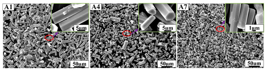
Figure 2.
SEM morphology of samples A1, A4 and A7 prepared in hydrochloric acid solution.
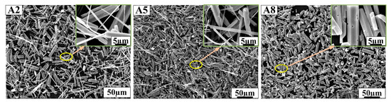
Figure 3.
SEM morphology of samples A2, A5 and A8 prepared in nitric acid solution.
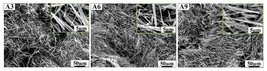
Figure 4.
SEM morphology of samples A3, A6 and A9 prepared in sulfuric acid solution.
As shown above, samples A1, A4 and A7 showed perfect hexagonal prism morphology and were prepared in hydrochloric acid solution. Samples A2, A5 and A8 prepared in nitric acid solution have a large number of hexagonal prism structures and a small number of one-dimensional linear structures, but sample A8 showed hexagonal prism morphology and a large number of small cavities on the surface. Samples A3, A6 and A9 prepared in sulfuric acid solution had fibrous structures, which followed a certain direction. In Figure 2, the edge of h-MoO3 gradually disappears as the concentration of AHM, the reaction temperature and the reaction time increase. The length of the hexagonal prisms is about 20 µm, and the length of the hexagonal sides is about 2 µm in samples A1, A4 and A7. The hexagonal prisms of h-MoO3 became rounded and smooth in sample A7. With the decrease in reaction temperature, the increase in AHM concentration and the prolongation of reaction time, it can be found that the hexagonal prism morphology of h-MoO3 becomes more obvious in Figure 4. Sample A8 with complete hexagonal prism morphology shows that the length of the hexagonal prisms is about 20 µm, and the side length of the hexagonal is about 2 µm.
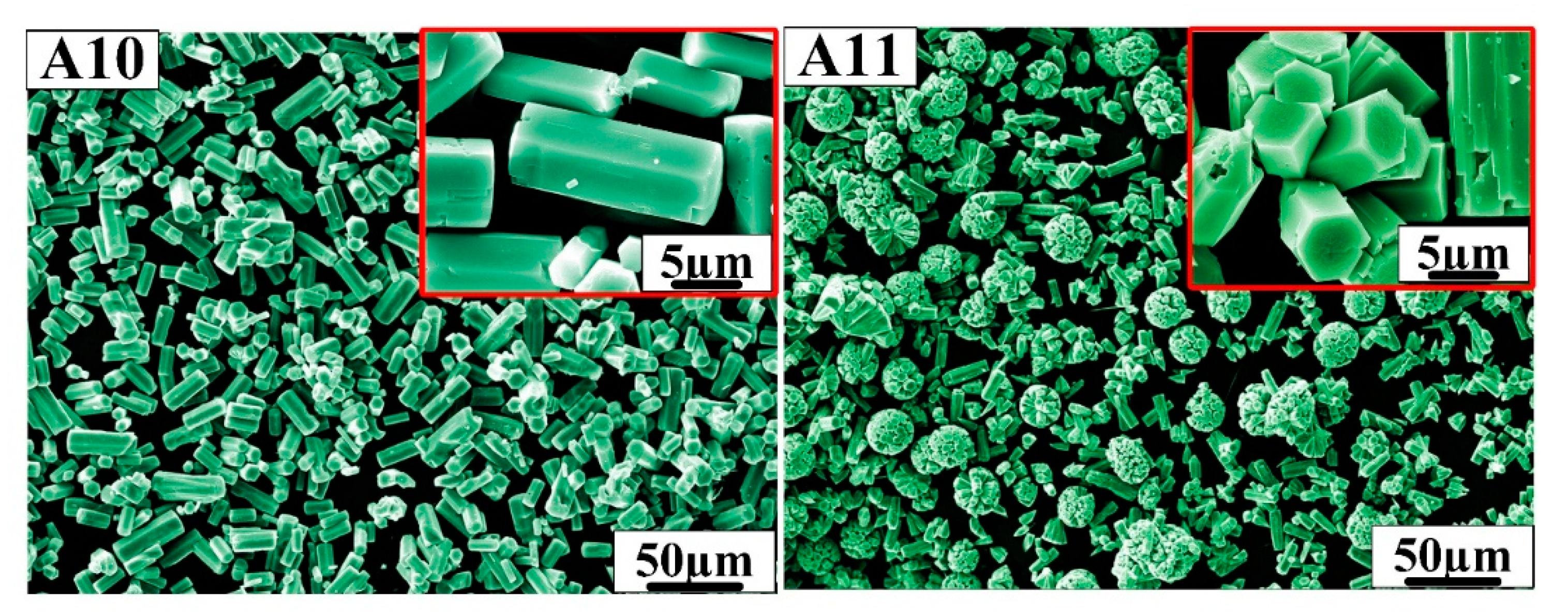
In order to prepare more ideal hexagonal prisms of h-MoO3, according to the above research formulation, A10 and A11 were designed. Figure 5 shows the SEM morphology of samples A10 and A11. Sample A10 has an ideal hexagonal prism morphology with well-defined angles. The length of the hexagonal prisms is approximately 10 µm and the side length of the hexagon is approximately 2 µm, which has a smaller aspect ratio than samples A1, A4 and A7. It can be seen from the A11 sample that hexagonal prisms grow together to form a spherical structure over time, and the diameter of the ball is about 20 µm.

Figure 5.
SEM morphology of samples A10 and A11.
It can be seen from the above results that h-MoO3 can be synthesized with different morphologies by controlling the reaction conditions. For example, h-MoO3 grows into ideal hexagonal prisms in hydrochloric acid solution. When the reaction time is extended to 14 h, hexagonal prism h-MoO3 containing many holes will combine together to present a spherical structure in nitric acid solution. α-MoO3 showed a fibrous microstructure in sulfuric acid solution. The reasons why the samples exhibit different morphologies are carefully discussed in the next section of this paper.
3.3. Growth Mechanisms
From the results of the above studies, it can be determined that there are differences in the growth mechanism of h-MoO3 in different growth environments. When AHM is dissolved in water, NH4+ and MoO42− are formed. When acid is added dropwise to AHM solution, MoO42− undergoes a condensation reaction to form homopolyacid ions such as H4Mo8O26 and H10Mo12O41 [23]. As the acidity increases, the degree of condensation becomes greater and the solution appears gelatinous. When the temperature is increased to 40–60 °C, the homopolyacid ion undergoes hydrolysis to produce monohydrated molybdic acid (H2MoO4·H2O). H2MoO4·H2O consists of an octahedral coordination of MoO5(H2O) unit layers, where the Mo atom occupies the center of the octahedron, the O atom occupies the six top corners of the octahedron and one of the six O atoms is present as H2O. As the temperature increases, in [MoO6] the octahedral nucleus grows anisotropically along the preferred growth direction under the action of NH4+, and six [MoO6] octahedral nuclei are connected by vertices to form the O-Mo-O structure, and then grow around a NH4+ along the Z-axis to form a one-dimensional structure [24]. According to the step growth mechanism and Bravais rule, crystal growth in solution means that structural units are incorporated into the crystal. The crystal provides the growth position of the structural units, in which the growth rate perpendicular to its surface is proportional to the density of the growth position, which depends on the growth temperature and the crystallographic orientation. The crystalline surfaces with a small surface network density are eliminated because of the fast growth rate, so that crystalline surfaces with a large surface network density are retained. This results in the final morphology of the crystal, surrounded by crystalline faces with high face-net density forming hexagonal prisms of h-MoO3. As the crystal grows, the concentration of the growth unit of [MoO6] octahedra of h-MoO3 in solution decreases, according to the Thomson Gibbs equation variation [25], as shown in Equation (3).
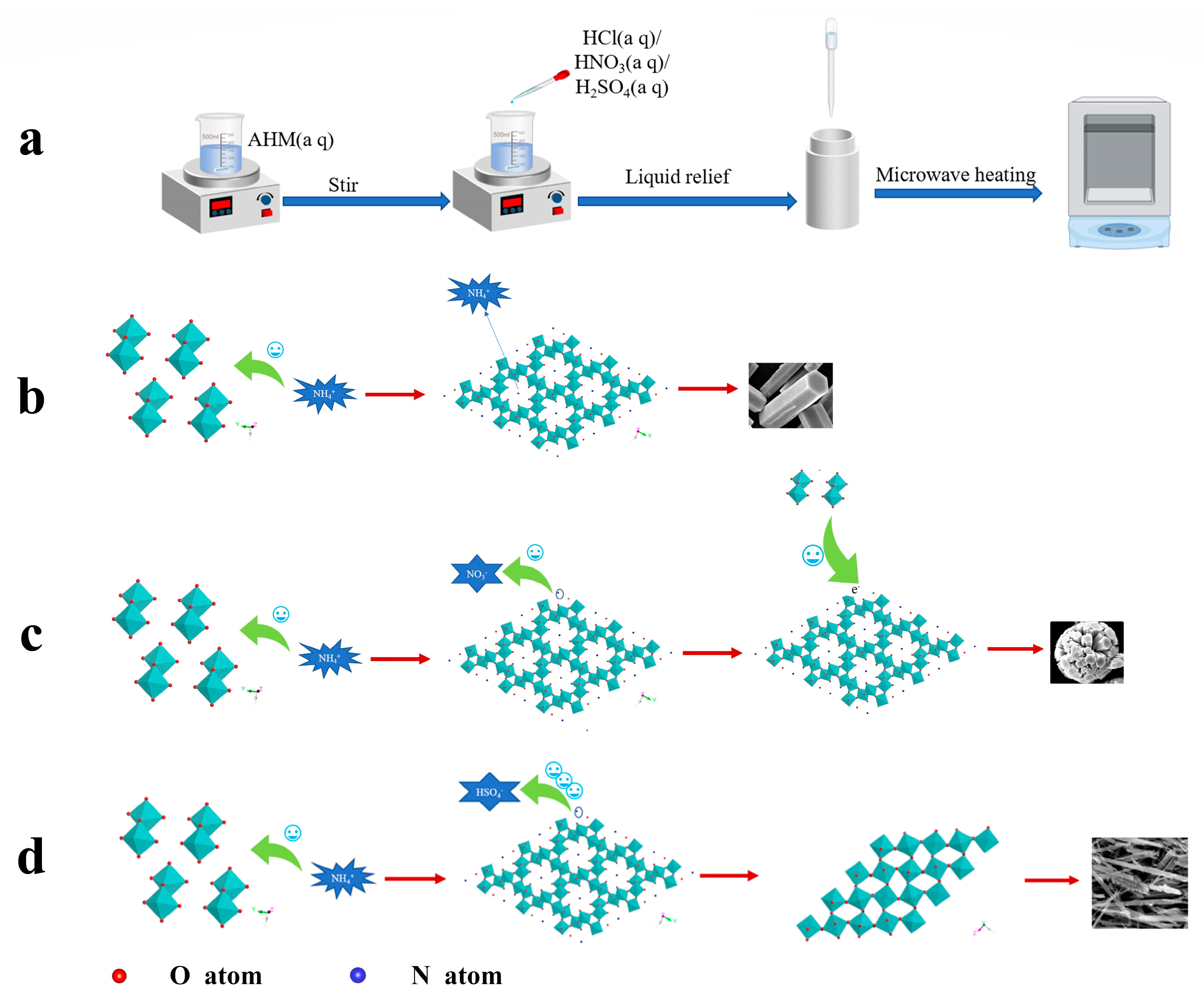
Since the oversaturation of small grains is higher than that of large grains, it is preferred to dissolve them in the solution, which will lead to the increase in the concentration of [MoO6] octahedra in the solution, and the formation of oversaturated solution continues on the steps of large grains to form nanoparticles. Multiple single-crystal nanoparticles with different orientations make the crystal orientation the same through particle rotation, and then these small single crystals grow into a large single crystal through oriented attachment. A schematic representation of the growth mechanism is shown in Figure 6.

Figure 6.
Schematic diagram of MoO3 growth mechanism: (a) flow chart of the experiment, (b) the formation mechanism of hexagonal prism h-MoO3, (c) the formation mechanism of spherical h-MoO3, (d) the formation mechanism of fibrous α-MoO3.
In a solution environment, the structural unit of the [MoO6] octahedron needs to overcome the binding energy ∆U (kcal/mol) with the solvent molecule and then combine with other [MoO6] octahedra to form a critical nucleus. The nucleation rate J0 (cm−3/s) is proportional to the frequency of the critical nucleus ω* (s−1), where ω* is proportional to the solute concentration C, where the solute concentration C is expressed as the number of molecules per cubic centimeter (cm−3), and the expression for ω* is given in Equation (4) [25].
It can be seen from the equation that the frequency of critical nuclei ω* increases as the concentration of AHM increases. It results that the nucleation rate J0 becomes larger. For the solution system, the high concentration of AHM solution will produce more crystal nuclei and form more grains. Since the amount of AHM is determined, the size of the crystals in solution will be smaller. Combined with SEM topography, it can be found that the average size of sample A7 is smaller than those of samples A1 and A4. When the concentration reaches a certain level, the nuclei collide with each other to produce agglomeration [26]. Then the anisotropic growth was carried out to form the spherical structure of sample A11.
From the SEM morphology results, the morphology of h-MoO3 varies significantly under different acid solutions. The morphology of h-MoO3 prepared using hydrochloric acid is ideal, with a smooth surface and few crystal defects. It can be assumed that the small h-MoO3 grains grow in the hydrochloric acid solution mainly in the Ostwald ripening mode. Smaller crystals in the solute dissolve and redeposit on larger crystals. The surface of the crystals thus grown produced fewer defects, probably due to the fact that Cl− reduced the binding between the [MoO6] octahedra and the solvent, allowing for more solution desolvation adsorption onto the grain surface. There are many defects on h-MoO3 surfaces prepared by nitric acid solution, which may be due to the dominant adhesion growth of crystals at the later stage of growth with the decrease in solute concentration in solution. The morphology of the samples prepared with concentrated sulfuric acid is fibrous, which may be because NH4+ is attracted by SO42− and cannot enter the six-membered ring of [MoO6]. Therefore, h-MoO3 lacks the structural support of NH4+ and cannot exist stably, thus forming α-MoO3. At the same time, sulfuric acid acts as a dispersant, hindering the adhesion between small grains and forming fibrous structures. Therefore, the influence of SO42−, NO3− and Cl− on sample morphology is attributed to their influence on NH4+. The high electricity price of SO42− and the high ion mass have a significant attractive effect on NH4+, which leads to the failure of the stable existence of h-MoO3. NO3− also has an attractive effect on NH4+, which leads to a small amount of NH4+ escaping in the ion channel of h-MoO3. Therefore, a small number of [MoO6] six-membered rings lack NH4+, and the electricity price is in an unbalanced state. Defects easily occur in the crystal growth process, resulting in holes on the surface of hexagonal columns. In addition, due to the existence of defects, crystals easily combine with each other in the growth process to form a spherical structure. Cl− has almost no effect on NH4+, so the crystals have fewer defects during growth.
In general, the metastable phase h-MoO3 is formed at a lower temperature than α-MoO3. When reaction temperature is increased, h-MoO3 is converted to α-MoO3 [10]. Combined with XRD and SEM results, when the sample was prepared in nitric acid solution, h-MoO3 was converted to α-MoO3 at 200 °C. In sulfuric acid solution, h-MoO3 was converted to α-MoO3. The preparation of h-MoO3 with hydrochloric acid does not involve a crystallographic transformation, but a slight dissolution of the angles of the hexagonal prism h-MoO3 occurs with a temperature increase. According to Ostwald’s step rule, in a hydrothermal reaction system, the crystal generates thermodynamic metastable phase h-MoO3 preferentially because of its high nucleation rate. With the increase in temperature, the thermal motion of ions in the hydrothermal system increases, resulting in the dissolution and regeneration of metastable phase h-MoO3 into stable phase α-MoO3 [27]. For the S and K surfaces at the angular position of hexagonal prism h-MoO3, the crystal surface density and surface energy are higher than for other surfaces, and they dissolve preferentially. This causes the edges of the sample to become rounded at relatively high temperatures.
Samples were prepared by the microwave hydrothermal method. Compared with the ordinary hydrothermal method, the temperature field of the hydrothermal environment produced by the microwave method is more uniform. So, over time, the crystal will reach a stable state, with anisotropic growth into an ideal shape.
3.4. UV–Vis Diffuse Reflectance Spectra Study
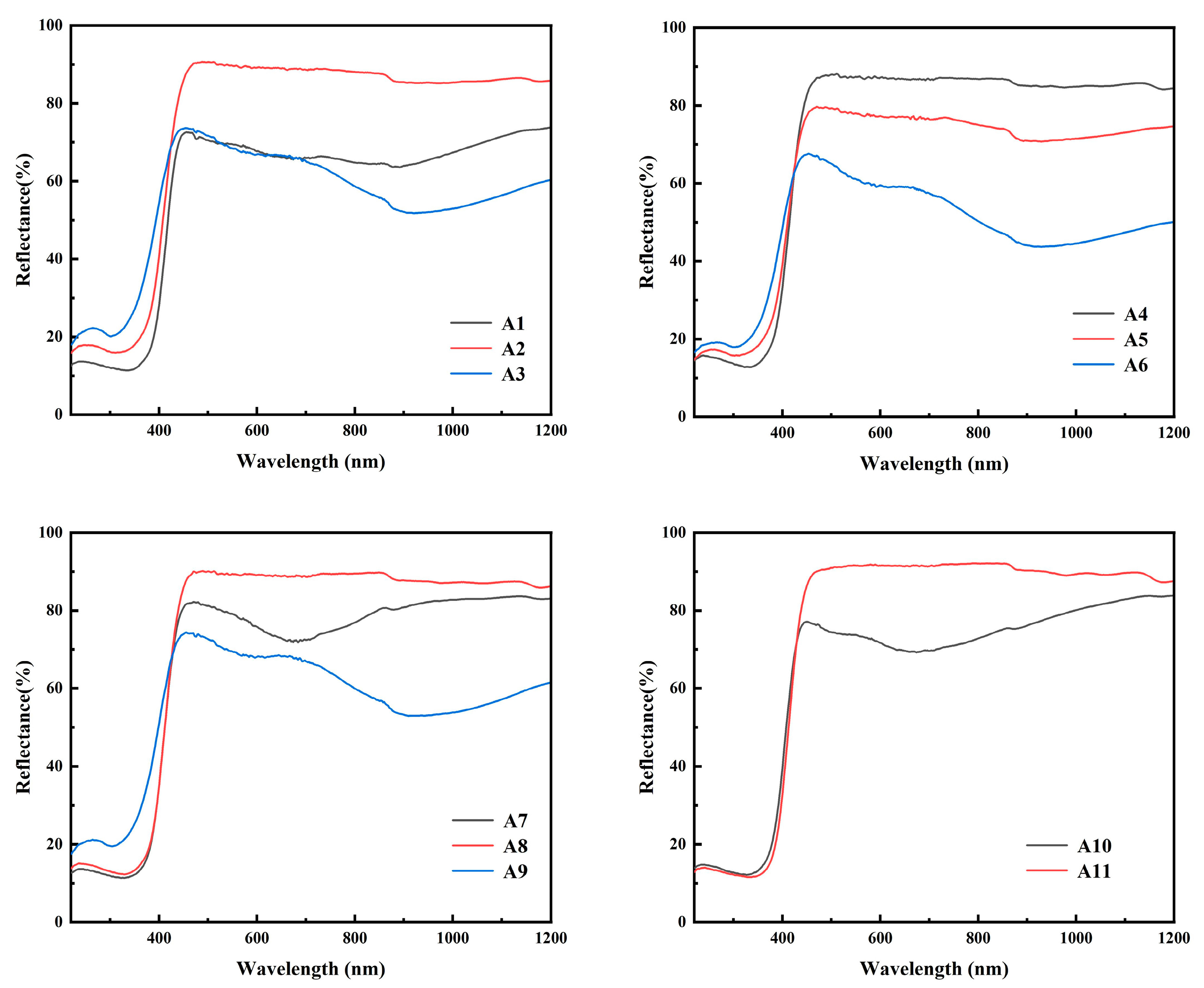
As shown in Figure 7, the reflectance drops sharply when the wavelength is about 420 nm in diffuse reflection, indicating that the sample absorbs the energy of light in this wavelength range. The phenomenon of blue shift of absorption peaks in samples A3, A6 and A9 indicates that these samples have a larger band gap and require more energy illumination to make the electron transition. The band gap width of the sample can be obtained through the Tauc plot method, which is mainly based on the formula proposed by Tauc, Davis and Mott et al. This is Equation (5) [28]. The Kubelka–Munk function is Equation (6) [29].
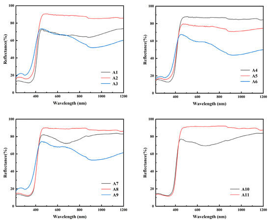
Figure 7.
UV–Vis diffuse reflectance spectra of samples A1–A11.
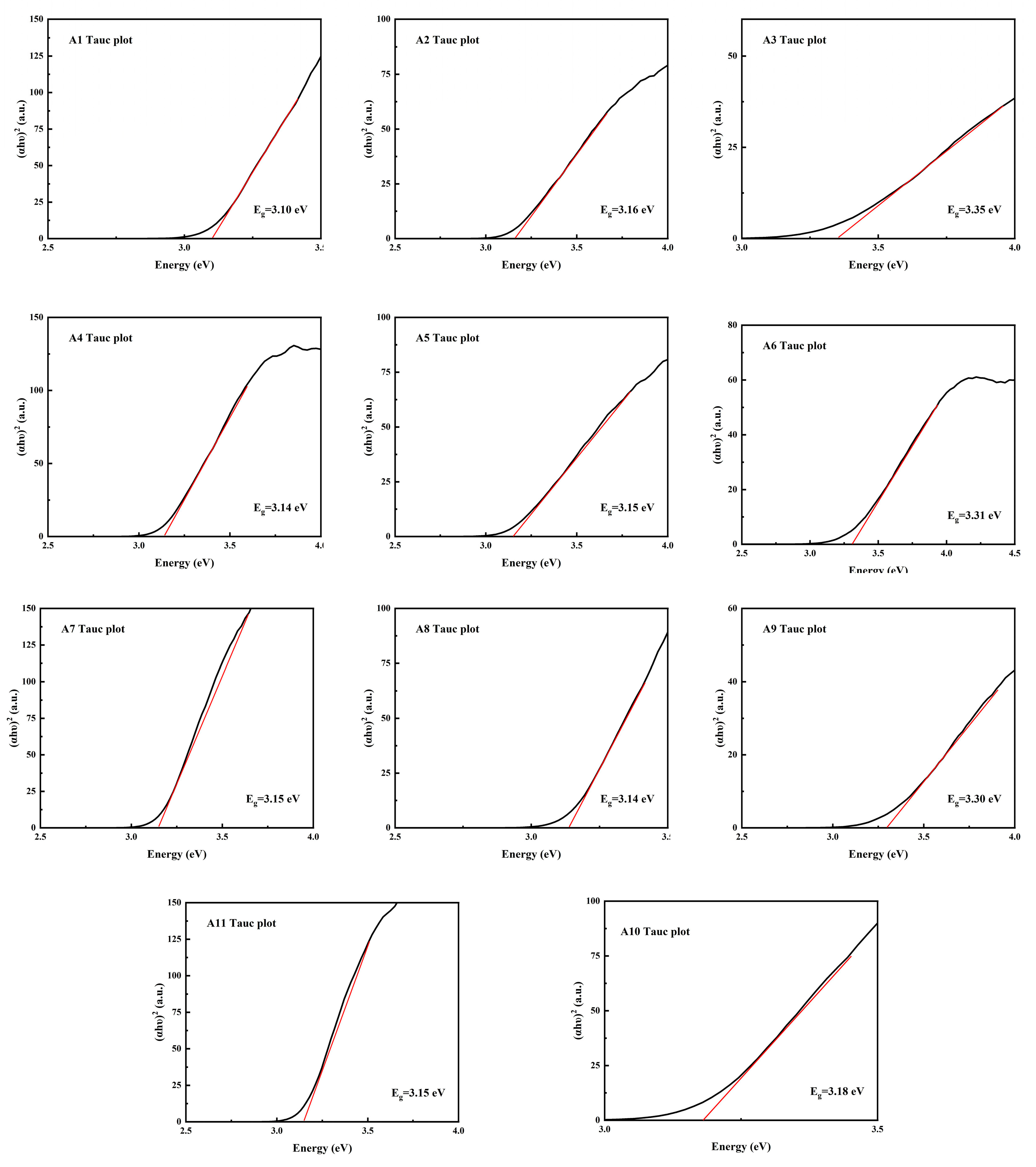
As shown in Figure 8, it can be found that the band gap Eg of samples A3, A6 and A9 is larger, which is consistent with the diffuse reflection spectrum. As h-MoO3 exists as a metastable phase and there are a large number of O-vacancies in the crystal, the band gap of h-MoO3 is narrower than that of α-MoO3.
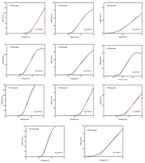
Figure 8.
Band gap calculation using Kubelka–Munk (K–M) function of samples A1–A11.
3.5. Photocatalytic Study of MB Degradation
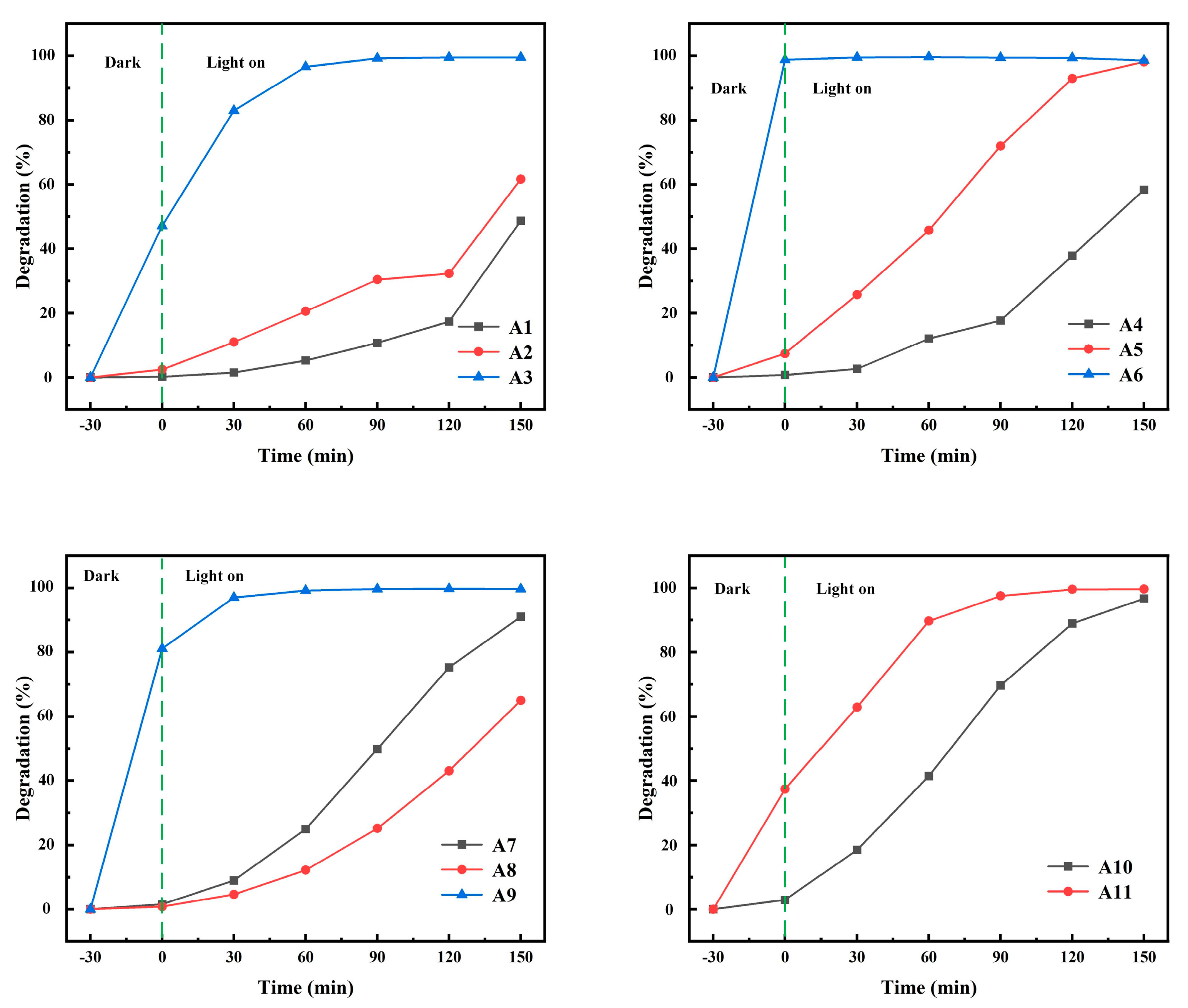
The degradation rate of MB under UV irradiation was used to characterize the photocatalytic performance of samples A1–A11. The relationship between the degradation rate of MB and time is shown in Figure 9. With the increase in reaction time, the degradation rate of MB solution increased gradually. The degradation rates of MB were 49%, 62%, 100%, 58%, 98%, 99%, 91%, 65%, 100%, 97% and 100%, respectively, after 3.5 h of ultraviolet radiation. Obviously, α-MoO3 generated in sulfuric acid solution had the highest removal rate of MB under dark conditions. The A11 sample also has good adsorption performance, with the adsorption rate reaching 40% in 30 min. The degradation rate of A11 is similar to that of A3, but their degradation modes are fundamentally different. The A11 sample mainly depends on its spherical structure to increase the adsorption performance, while the A3 sample mainly depends on the specific surface area. The main reason is that α-MoO3 is nanofibrous and has a strong adsorption effect on MB, and the adsorption rate of the A9 sample to MB is up to 80%. h-MoO3 produced in hydrochloric acid solution has almost no adsorption on MB, mainly because of its fewer crystal defects. The spherical A11 samples showed strong adsorption and photocatalysis for MB. It can be found from the SEM topography that the exposed surface of the A11 sample is the bottom surface of each small hexagonal prism, which indicates that there are more adsorption sites and photocatalytic active sites on the bottom surface of the hexagonal prisms. The values of k and R2 are obtained from Table 4. R2 stands for linear correlation coefficient. As can be seen from Table 4: k3 = 0.93, k11 = 0.023. This indicates that the A3 and A11 samples have better photocatalytic performance than other samples. At the same time, R12 = 0.9, R112 = 0.95. This indicates that it conforms to the kinetic equation [30]. R12 and R62 are 0.64 and 0.41, respectively, indicating that the fitting results of A1 and A6 do not agree with the first-order kinetic equation. This was mainly due to the sudden improvement of degradation performance of A1 samples in the last 30 min. The sudden improvement of the photocatalytic performance of the A1 sample may be due to the sensitization effect of methylene blue on the A1 sample after full contact with methylene blue. The main reason for the low R62 is the high adsorption performance of the A6 sample. In the adsorption equilibrium stage, the A6 sample adsorbed almost all the methylene blue in the solution. The BET surface area of A10 is 0.4357 m2/g and the BET surface area of A11 is 0.3300 m2/g. Through SEM, it can be found that the spherical structure of the A11 sample is a combination of many hexagonal columns. Therefore, the specific surface area of A11 is smaller than the hexagonal column structure of the A10 sample. However, the methylene blue degradation rate of the A11 sample is higher than that of the A10 sample, which indicates that the A11 sample has better photocatalytic performance than the A10 sample. Therefore, it is concluded that the spherical structure of h-MoO3 has the best photocatalytic performance.
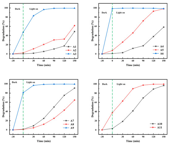
Figure 9.
The relationship between degradation rate of MB and time.
The degradation rate η was (1). The photocatalytic reaction process is generally described by the Langmuir–Hinshelwood (L-H) Equation (2).
where Ct and At are the concentration (mg/L) and absorbance of MB solution at time t, respectively. C0 and A0 are the initial concentration (mg/L) and absorbance of MB solution, respectively.
where k is the rate constant.
where ∆µ is the supersaturation (J/mol), is the specific surface energy (J/cm2), c is the volume of the crystal (cm3), is the edge length (cm).
where r* is the critical nucleation radius (cm), υ is the frequency factor (s−1), λ is the average free range of the grains in solution (cm).
InC0/C = InA0/A = kt
(αhυ)1/n = A(hυ − Eg)
The value of n expresses the transition category (n = 0.5 for indirect and n = 2 for direct transition), whereas A, α and hυ show the constant value, absorbance coefficient and photon’s energy, correspondingly.
where K is the absorption coefficient, S is the reflection coefficient and R∞ refers to the reflectance relative to the infinitely thick barium sulfate sample, which is the reflectance R measured in the diffuse reflection spectrum. F(R) is proportional to α, and substituting F(R) for α gives Eg.
4. Conclusions
In this study, h-MoO3 and α-MoO3 with different morphologies were prepared by the microwave hydrothermal method using AHM as the precursor. The effects of morphology and crystal structure on optical properties and photocatalytic activity were investigated. In the solution of nitric acid, when the reaction temperature reaches 200 °C, there will be α-MoO3 to h-MoO3 transition. It can be observed from the morphology that the hexagon prism h-MoO3 take shape fibers with the gradual increase in temperature. The overall results show that the distribution of univalent cations such as NH4+ ions and crystalline water molecules plays an important role in the stability of metastable hexagonal structures. Compared with other samples, the band gap of A3, A6 and A9 samples is larger, and adsorption plays a dominant role. A11 has both photocatalytic and adsorption properties. k11 = 0.02254 min−1, which can completely degrade MB within 2 h. The spherical structure of h-MoO3 has the best photocatalytic performance.
Author Contributions
Writing—review and editing, resources, methodology, J.W.; writing—reviewand editing, methodology, investigation, formal analysis, Z.C.; resources, project administration, funding acquisition, conceptualization, X.X.; formal analysis, data curation, P.W.; investigation, G.X.; formal analysis, X.Z. All authors have read and agreed to the published version of the manuscript.
Funding
This research was funded by the Foshan Key Field Science and Technology Research Project (grant number 2120001009066).
Data Availability Statement
Not applicable.
Acknowledgments
The authors acknowledge the financial support of the Foshan Key Field Science and Technology Research Project (grant number 2120001009066).
Conflicts of Interest
The authors declare no conflict of interest.
References
- Zhang, J.; Li, H.; Jiao, G.; Wang, J.; Li, J.; Li, M.; Jiang, H. Spatial Pattern of Technological Innovation in the Yangtze River Delta Region and Its Impact on Water Pollution. Int. J. Environ. Res. Public Health 2022, 19, 7437. [Google Scholar] [CrossRef]
- Liu, Y.; Wang, P.; Gojenko, B.; Yu, J.; Wei, L.; Luo, D.; Xiao, T. A review of water pollution arising from agriculture and mining activities in Central Asia: Facts, causes and effects. Environ. Pollut. 2021, 291, 118209. [Google Scholar] [CrossRef]
- Gomes-Silva, G.; Cyubahiro, E.; Wronski, T.; Riesch, R.; Apio, A.; Plath, M. Water pollution affects fish community structure and alters evolutionary trajectories of invasive guppies (Poecilia reticulata). Sci. Total. Environ. 2020, 730, 138912. [Google Scholar] [CrossRef]
- Wang, H.; Guan, N.; Feng, Z.; Xiang, W.; Zhao, H.; Zhang, X. Constructing defect engineered 2D/2D MoO3/g-C3N4 Z-scheme heterojunction for enhanced photocatalytic activity. J. Alloys Compd. 2022, 926, 166964. [Google Scholar] [CrossRef]
- Ali, A.; Shoeb, M.; Li, B.; Khan, M.A. Photocatalytic degradation of antibiotic drug and dye pollutants under visible-light irradiation by reduced graphene oxide decorated MoO3/TiO2 nanocomposite. Mater. Sci. Semicond. Process. 2022, 150, 106974. [Google Scholar] [CrossRef]
- Ren, P.; Ren, X.; Xu, J.; Li, H.; Zheng, Y.; Hong, Y.; Lin, Y.; Zhou, Y.; Chen, Y.; Zhang, W. Excellent adsorption property and mechanism of oxygen vacancies-assisted hexagonal MoO3 nanosheets for methylene blue and rhodamine b dyes. Appl. Surf. Sci. 2022, 597, 153699. [Google Scholar] [CrossRef]
- Kateshiya, M.R.; Malek, N.I.; Kailasa, S.K. Green fluorescent carbon dots functionalized MoO3 nanoparticles for sensing of hypochlorite. J. Mol. Liq. 2022, 351, 118628. [Google Scholar] [CrossRef]
- Liu, S.; Yang, Z.; Zhao, L.; Zhang, Y.; Xing, Y.; Fei, T.; Zhang, H.; Zhang, T. Glucose-assisted combustion synthesis of oxygen vacancy enriched α-MoO3 for ethanol sensing. J. Alloys Compd. 2022, 902, 163711. [Google Scholar] [CrossRef]
- Santhosh, S.; Kumar, A.N.; Kennedy, J.; Subramanian, B. Electrochromic response of pulsed laser deposited oxygen deficient monoclinic β-MoO3 thin films. Electrochim. Acta 2022, 354, 136745. [Google Scholar] [CrossRef]
- Chua, W.H.; Yaacob, M.H.; Tan, C.Y.; Ong, B.H. Chemical bath deposition of h-MoO3 on optical fibre as room-temperature ammonia gas sensor. Ceram. Int. 2021, 47, 32828–32836. [Google Scholar] [CrossRef]
- Ghalehghafi, E.; Rahmani, M.B. Hydrothermal temperature effect on the growth of h-MoO3 thin films using seed layers and their photoluminescence properties. Mater. Sci. Semicon. Proc. 2022, 137, 1–10. [Google Scholar] [CrossRef]
- Chithambararaj, A.; Rajeswari Yogamalar, N.; Bose, A.C. Hydrothermally synthesized h-MoO3 and α-MoO3 nanocrystals: New findings on crystal-structure-dependent charge transport. Cryst. Growth Des. 2016, 16, 1984–1995. [Google Scholar] [CrossRef]
- Chot, C.Y.; Chong, M.N.; Soh, A.K.; Ocon, J.D. Unravelling the roles of H+, Na+ and K+ cations over the self-photorechargeability of a Pt-mediated MoO3 photoanode-driven photoelectrochemical system: Experimental and DFT study. J. Environ. Chem. Eng. 2022, 10, 107252. [Google Scholar] [CrossRef]
- Niu, Y.; Li, X.; Su, H.; Li, J.; Qi, Y. Formation of three dimensional porous h-MoO3 architecture and its application in supercapacitors. Mater. Lett. 2022, 316, 132062. [Google Scholar] [CrossRef]
- Li, X.; Yang, H.; Hu, X.; Wu, Q.; Xiong, W.; Qin, Z.; Xie, C.; Zeng, D. Exposed Mo atoms induced by micropores enhanced H2S sensing of MoO3 nanoflowers. J. Hazard. Mater. 2022, 429, 128270. [Google Scholar] [CrossRef]
- Cai, Z.; Song, Y.; Jin, X.; Wang, C.C.; Ji, H.; Liu, W.; Sun, X. Highly efficient AgBr/h-MoO3 with charge separation tuning for photocatalytic degradation of trimethoprim: Mechanism insight and toxicity assessment. Sci. Total Environ. 2021, 781, 146754. [Google Scholar] [CrossRef]
- Kumar, N.; Kumar, R. Efficient adsorption of methylene blue on hybrid structural phase of MoO3 nanostructures. Mater. Chem. Phys. 2022, 275, 125211. [Google Scholar] [CrossRef]
- Kamble, B.B.; Ajalkar, B.D.; Tawade, A.K.; Sharma, K.K.; Mali, S.S.; Hong, C.K.; Bathula, C.; Kadam, A.N.; Tayade, S.N. Ionic liquid assisted synthesis of h-MoO3 hollow microrods and their application for electrochemical sensing of Imidacloprid pesticide in vegetables. J. Mol. Liq. 2021, 324, 115119. [Google Scholar] [CrossRef]
- Wang, Y.; Yu, Y.; Liu, Z.; Qiao, H.; Zhang, Z.; Ishizaki, T.; Hu, X. Catalytic performance of oxygen vacancies-enriched h-MoO3 in lithium-oxygen batteries. J. Alloys Compd. 2022, 927, 166927. [Google Scholar] [CrossRef]
- Jamshaid, M.; Khan, H.M.; Nazir, M.A.; Wattoo, M.A.; Shahzad, K.; Malik, M.; Rehman, A.U. A novel bentonite–cobalt doped bismuth ferrite nanoparticles with boosted visible light induced photodegradation of methyl orange: Synthesis, characterization and analysis of physiochemical changes. Int. J. Environ. Anal. Chem. 2022, 805, 139939. [Google Scholar] [CrossRef]
- Paraguay-Delgado, F.; Mendoza Duarte, M.E.; Kalu, O.; Estrada Moreno, I.A.; Alonso-Lemus, I.; Lardizábal-G, D. h-MoO3 phase transformation by four thermal analysis techniques. J. Therm. Anal. Calorim. 2022, 140, 735–741. [Google Scholar] [CrossRef]
- Sen, S.K.; Paul, T.C.; Dutta, S.; Hossain, M.N.; Mia, M.N.H. XRD peak profile and optical properties analysis of Ag-doped h-MoO3 nanorods synthesized via hydrothermal method. J. Mater. Sci. Mater. Electron. 2020, 31, 1768–1786. [Google Scholar] [CrossRef]
- Kumar, S.; Singh, A.; Singh, R.; Singh, S.; Kumar, P.; Kumar, R. Facile h-MoO3 synthesis for NH3 gas sensing application at moderate operating temperature. Sens. Actuators B Chem. 2020, 325, 128974. [Google Scholar] [CrossRef]
- Wang, L.; Li, H.; Xue, Z. Synthesis of h-MoO3 nanorods and h-/α-MoO3 composites, and their photocatalytic performance. T Nonferr. Metal Soc. 2022, 32, 1–22. [Google Scholar]
- Markov, I.V. Crystal Growth for Beginners Fundamentals of Nuclestion, Crystal Growth and Epitaxy; Beijing Education Press: Beijing, China, 2018; pp. 50–90. [Google Scholar]
- Moura, J.V.B.; Silveira, J.V.; da Silva Filho, J.G.; Souza Filho, A.G.; Luz-Lima, C.; Freire, P.T.C. Temperature-induced phase transition in h-MoO3: Stability loss mechanism uncovered by Raman spectroscopy and DFT calculations. Vib. Spectrosc. 2018, 98, 98–104. [Google Scholar] [CrossRef]
- de Sá, M.L.; Nobre, F.X.; Silva, L.D.S.; Sousa, G.D.S.; Takeno, M.L.; Júnior, E.A.A.; de Matos, J.M.E.; de Santos, M.R.M.C. Preparation of new h-MoO3 rod-like microcrystals for effective removal of cationic dye in aqueous solution. Int. J. Environ. Res. 2021, 15, 105–124. [Google Scholar] [CrossRef]
- Kumar, P.S.; Selvakumar, M.; Babu, S.G.; Karuthapandian, S.; Chattopadhyay, S. CdO nanospheres: Facile synthesis and bandgap modification for the superior photocatalytic activity. Mater. Lett. 2015, 151, 45–48. [Google Scholar] [CrossRef]
- Chithambararaj, A.; Bose, A.C. Hydrothermal synthesis of hexagonal and orthorhombic MoO3 nanoparticles. J. Alloys Compd. 2011, 509, 8105–8110. [Google Scholar] [CrossRef]
- Shahzad, K.; Najam, T.; Bashir, M.S.; Nazir, M.A.; Rehman, A.U.; Shah, S.S.A. Fabrication of Periodic Mesoporous Organo Silicate (PMOS) composites of Ag and ZnO: Photo-catalytic degradation of methylene blue and methyl orange. Inorg. Chem. Commun. 2020, 123, 108357. [Google Scholar] [CrossRef]
Disclaimer/Publisher’s Note: The statements, opinions and data contained in all publications are solely those of the individual author(s) and contributor(s) and not of MDPI and/or the editor(s). MDPI and/or the editor(s) disclaim responsibility for any injury to people or property resulting from any ideas, methods, instructions or products referred to in the content. |
© 2023 by the authors. Licensee MDPI, Basel, Switzerland. This article is an open access article distributed under the terms and conditions of the Creative Commons Attribution (CC BY) license (https://creativecommons.org/licenses/by/4.0/).