Abstract
Biomedicine requires materials able to respond to specific needs without affecting the organism. Organic–inorganic fibrillar polymeric matrices possess unique properties that may fulfill these needs. In the present study, different topology-controlled poly(ε-caprolactone)-based fibrillar matrices containing glycine betaine at varying concentrations (0.5, 1, and 2% w/v) were prepared via electrospinning. The matrices were used as substrates in calcium carbonate crystallization assays with gas diffusion to obtain a single organic–inorganic hybrid material. The resulting matrices and crystalline material were characterized using spectroscopic, microscopic, and thermogravimetric analyses. The incorporation of glycine betaine into a poly(ε-caprolactone) mesh modified the diameter of the fibers, without affecting the thermal behavior of the matrices. However, the chemical and morphological characteristics of the matrices did influence in vitro inorganic mineralization. The thermogravimetric analysis of the matrices, performed after the mineralization tests, demonstrated the existence of a new organic–inorganic hybrid material with unique properties, which is discussed in the present study.
1. Introduction
Calcium carbonate (CaCO3) is the most abundant calcium salt on Earth and can be found in hydrated and anhydrous forms. Three known polymorphs exist for the anhydrous form: vaterite, aragonite, and calcite [1]. These polymorphs are present in marine sediments and rocks, in addition to forming part of living organisms (e.g., the exoskeleton of crustaceans, shells, and corals) through a natural process called biomineralization [2,3]. CaCO3 has been used in various fields of application. Its medical applications are of special interest, where its use has been described in bone implant and tissue engineering, drug delivery, etc., due to its biocompatibility and non-toxicity [1,4,5].
Organic–inorganic hybrid materials are a promising candidates for use in biomedicine [4]. In biomineralized hybrid materials, both the organic and inorganic components play an important role. The lesser organic component drives the mineralization process, and the greater inorganic component underlies the formation of the crystal, which closely interacts with the organic matrix. This matrix can, in turn, stabilize metastable structures, which occurs in corals that stabilize aragonite [6]. This is possible due to the presence of functional groups in the organic matrix produced by specialized cells that recognize and stabilize specific crystalline phases and that act as nucleation centers [3,7,8].
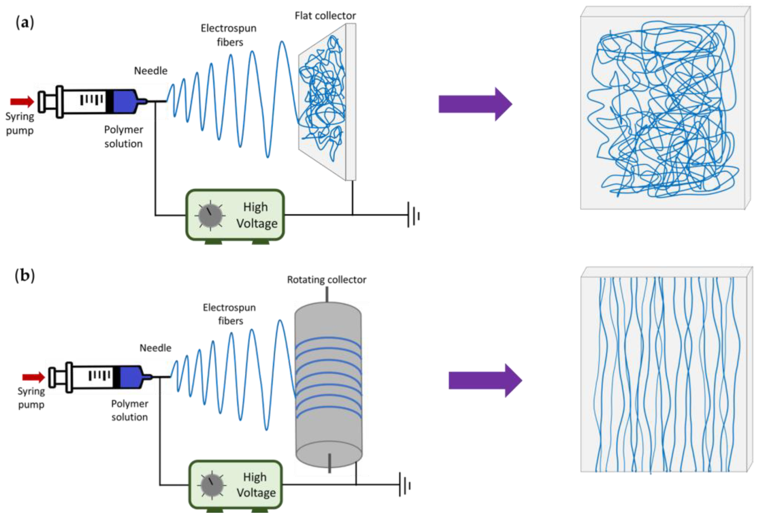
Electrospinning (ES) is a technique widely used in different fields, and it allows for the fabrication of fibrillar meshes composed of the nano/microfibers of polymeric materials with a high surface area [9,10,11]. Electrospinning consists of applying a high voltage to a polymer solution coming out of a metal needle; the drop of solution deforms and acquires a conical shape called a “Taylor cone”. When the applied potential exceeds the surface tension, fibers are formed and ejected to a collector; at the same time, the solvent evaporates, and a nano/microfiber mesh is formed [10,12,13]. An important aspect of ES is that it allows for the orientation of the functional groups of the polymeric material to be used during the fiber-manufacturing process. If a positive voltage is applied, the interface between the air and the polymer jet will be positively charged, which triggers the dipoles present in the solution to be attracted to the surface [10,14,15]. The final traits of the polymetric fibers depend on the environmental conditions (temperature and humidity), the characteristics of the material (viscosity, conductivity, molecular weight, etc.), and the parameters used (pressure, voltage, and needle–collector distance) [16].
In biomedicine, materials that can be applied in specific ways are needed, and a key challenge in responding to this need is the development of new hybrid nanostructure materials [17]. One interesting proposal is the preparation of organic–inorganic hybrid materials. Such preparations result in hybrid electrospun materials that present properties different to those of the originating materials. The optical, mechanical, and thermal properties, among others, of fibrillar polymeric meshes can be improved via the incorporation of inorganic materials [4,18,19].
The present study used a previously electrospun poly (ε-caprolactone) (P), a synthetic, biodegradable, and biocompatible aliphatic polyester with excellent mechanical and biomedical properties [3,20,21]. To propose a novel hybrid material, this study incorporated glycine betaine (N,N,N-trimethylglycine betaine) (G), a zwitterion osmolyte found in animal organisms, into the fibrillar polymeric matrices. Glycine betaine possesses a carboxylate group that can be negatively charged and a positively charged tetramethyl-ammonium group [22,23]. Glycine betaine has been used to improve the characteristics of polymeric membranes by increasing wettability and the antifouling property, among others [24], demonstrating its ability to decrease the adverse effects of medical devices by way of improving hemocompatibility when incorporated into polymeric matrices [22]. Additionally, G has nutraceutical characteristics and bioactive properties [25], and it has even been shown to improve the hemocompatibility of electrospun films [22].
Although each component of the fibrillar organic matrix influences the biomineralization process of CaCO3 via the presence of functional groups [3,26], up to now, only the fabrication of P matrices covered with vaterite for biomedical use has been reported [27]. However, this study is the first report on (i) the preparation of a novel electrospun polymer nanofiber (EPnF) mesh based on P and G (P/G-EPnF) and (ii) the use thereof as a template for the in vitro crystallization of CaCO3 through gas diffusion (GD) as a potential organic–inorganic hybrid nanofiber (P/G/CaCO3-EPnF) material for biomedical applications by generating a new hybrid material created from three components widely described and used in the biomedical area.
2. Materials and Methods
2.1. Reagents
Glycine betaine was purchased from Sigma-Chile (Santiago, Chile). Poly (ε-caprolactone) (Mw = 80,000) was purchased from Sigma-Aldrich (St. Louis, MO, USA). Calcium chloride dihydrate (CaCl2·2H2O), ammonium bicarbonate ((NH4)HCO3), and Tris(hydroxymethyl)aminomethane (TRIS), were purchased from Merck (Darmstadt, Germany). Ethyl acetate and acetic acid were obtained from Sigma-Aldrich (St. Louis, MO, USA). All water consumed in this research was Milli-Q grade water obtained using a BIOBASE (SCSJ-30V) instrument.
2.2. Preparation of P/G-EPnF
Poly (ε-caprolactone) 16% (w/v) was prepared in acetic acid/ethyl acetate/ultra-pure water 3:2:1 (v/v) at 40 °C under magnetic stirring for 6 h. To construct the P/G-EPnF meshes, 40% (w/v) G was dissolved in water under magnetic stirring for 10 min at 75 °C. This solution was added to a 3:2:1 (v/v/v) acetic acid/ethyl acetate/Milli-Q water mixture at concentrations of 0.5%, 1%, and 2 % (w/v), with the water replaced as needed to obtain each concentration. Subsequently, the P solution was added, and the resulting solution was kept at 40 °C under magnetic stirring for 6 h. After preparation, the solutions were deposited in 5 mL Luer-lock syringes (Nipro®, Osaka, Japan). The ES process was carried out in an ES LE-10 instrument (Fluidnatek®, Singapore). The proper working parameters for preparing the fibers are summarized in Table 1.

Table 1.
ES parameters for the preparation of A-P/G-EPnF and R- P/G-EPnF meshes.
Meshes containing no G are referred to herein as P/G0-EPnF, and those containing 0.5, 1, and 2 % (w/v) G are referred to as P/G0.5-EPnF, P/G1-EPnF, and P/G2-EPnF, respectively.
The topographic aspects of the P/G-EPnF meshes used as scaffolds in the CaCO3 mineralization study were checked. For this, fiber meshes with random (R-P/G-EPnF) or aligned (A-P/G-EPnF) distributions were obtained using a flat or a rotary (10 cm diameter) collector, respectively (Figure 1). Both collectors were covered with aluminum foil.
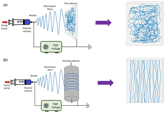
Figure 1.
Schematic representation of the electrospinning setup and the final distribution of the fibers in each type of collector. (a) Flat collector and (b) rotating collector.
2.3. Crystallization of CaCO3
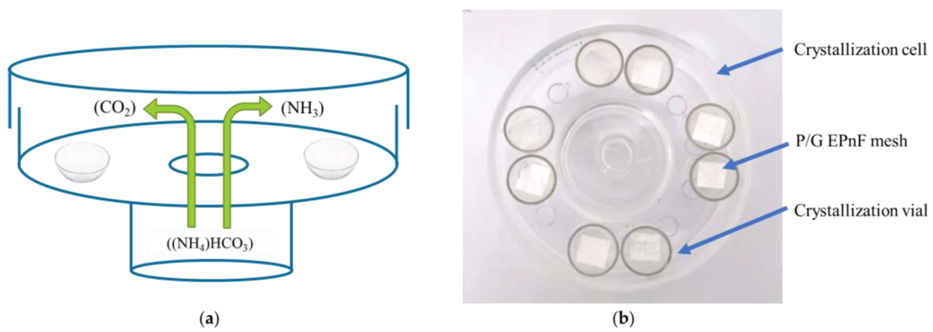
The GD technique was used to prepare CaCO3 crystals in vitro on P/G-EPnF meshes. The GD method was performed as we described in our previous works [28,29]. Briefly, a 200 mM CaCl2·2H2O solution was prepared in 200 mM TRIS at pH 9. These solutions were deposited in 1 mL crystallization vials containing cut P/G-EPnF meshes (8 × 8 mm). The vials were placed in a crystallization cell containing a 25 mM (NH4)HCO3 solution used to create a CO2 source (Figure 2). All GD assays were performed in an oven (LabTech®, Sorisole,Italy) at 25 °C for 24 h. After the crystallization time, the resulting meshes were washed with ethanol at increasing concentrations (50–100%), thereby obtaining hybrid matrices of P/G-EPnF with CaCO3 crystals (P/G/CaCO3-EPnF).
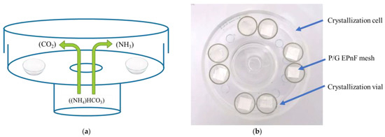
Figure 2.
Schematic representation and photograph of the GD crystallization method. (a) Schematic of the crystallization cell with crystallization vials inside, and (b) photograph (top view) of the crystallization cell with vials containing P/G EPnF meshes.
2.4. Characterization Techniques
2.4.1. Attenuated Total Reflectance–Fourier Transform Infrared Spectroscopy (ATR/FT-IR)
The G and P/G-EpnF meshes were evaluated with a Nicolet IS 50 instrument (Thermo Fisher Scientific, Waltham, MA, USA). Spectra were obtained in the range of 4000 to 500 cm−1 with a resolution of 4 cm−1, and the final spectrum corresponds to an average of 16 scans.
2.4.2. Contact Angle (CA)
The CA of the P/G-EPnF meshes was measured in a Dataphysics OCA 15EC machine (DataPhysics Instruments GmbH). A dosing volume of 12 µL ultrapure water was used. For this, 1 × 10 cm P/G-EPnF meshes were cut and glued to slides. Five replicates were performed for each assay. For aligned meshes, CA measurements were performed in both directions, i.e., frontal to the fibers and lateral to the fibers.
2.4.3. Scanning Electron Microscopy (SEM)
P/G-EPnF and P/G/CaCO3-EPnF were coated with a 10 nm layer of gold and analyzed using SEM with an Interspect-F50 instrument operating at 20 kV. The SEM images were analyzed using ImageJ software (NIH, http://rsb.info.nih.gov/ij/, accessed on 12 October 2022). A total of 3 representative images of each sample were used, and 100 fibers were measured (n = 300).
2.4.4. X-ray Diffraction (XRD)
The GB, P, CaCO3, P/G0-EPnF, and P/G/CaCO3-EPnF meshes were evaluated in a Siemens D-5000 machine with CuKα radiation. The Diffrac.Eva program (Bruker®, Billerica, MA, USA) was used to compare the different diffractograms and to determine the polymorphs of the CaCO3 crystalline material. The crystallography open database (COD) was used to index the peaks. The crystal structure was analyzed using the Rietveld refinement method, by using half-width at half-height (FWHM), calculated with Scherrer’s formula with TOPAS 4.2 software, Bruker AXS.
2.4.5. Thermogravimetric Analysis and Derivative Thermogravimetry (TGA/DTG)
P/G-EPnF and P/G/CaCO3-EPnF were evaluated using TGA/DTG with 1.5–8.5 mg of the sample, which was performed with a constant nitrogen flow rate of 30 mL/min and a constant 10 °C/min temperature increase rate from room temperature to 600 °C. The TGA/DTG measurements were performed on a NETZSCH TG 209 F3 Tarsus® instrument (Selb, Germany).
2.5. Statistical Analysis
The normality of the fiber diameter was evaluated using the Shapiro–Wilk test, and the homogeneity of variance was evaluated using Fligner–Killeen. According to the results, a parametric test using one-way ANOVA and Tukey’s multiple comparisons tests or a non-parametric test using the Kruskal–Wallis test was performed, followed by Dunn’s test. A p-value of ≤0.05 was considered statistically significant.
3. Results and Discussion
3.1. ATR/FT-IR Spectroscopy
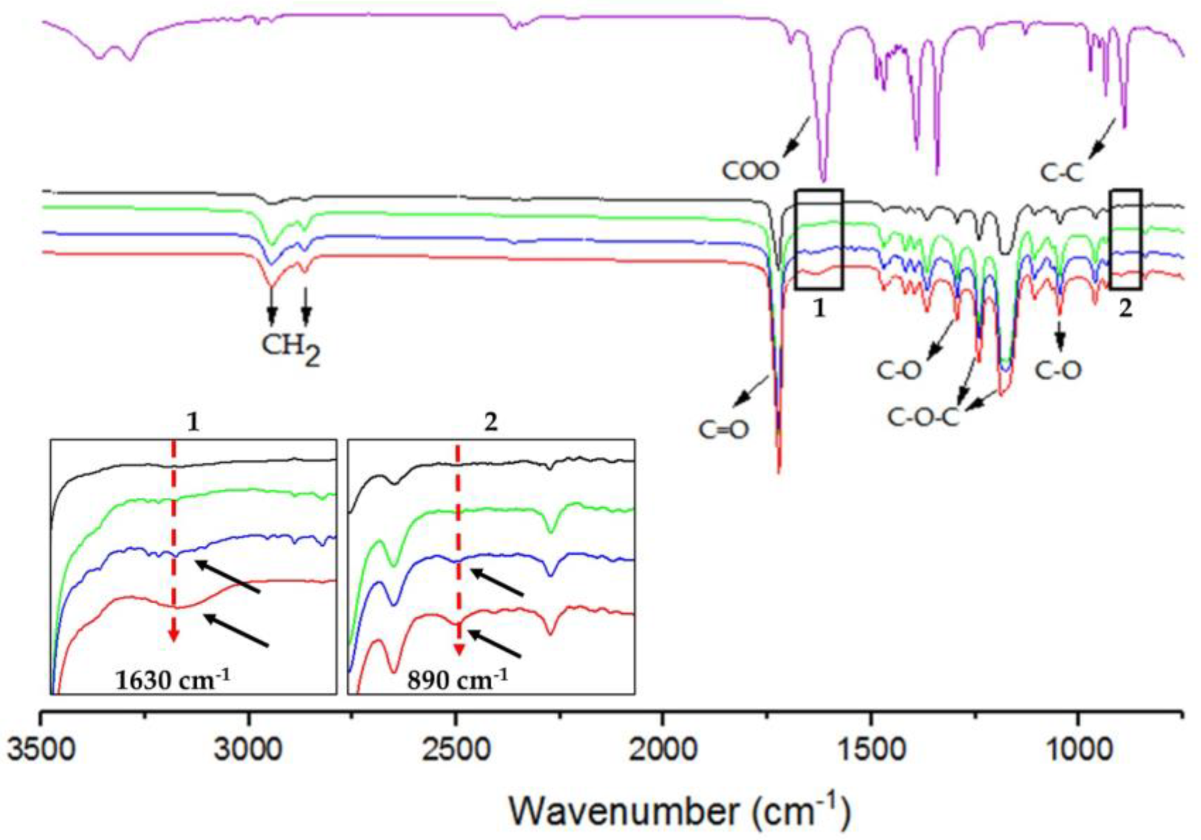
Infrared spectroscopy allows for the identification of functional groups in samples. Identified for G was a sharp absorption band at 3290 cm−1, associated with the -OH group [25], and the absorption bands at 890 cm−1 and 1630 cm−1 are associated with the v C-C and carboxylic groups, respectively (Figure 3) [23,30]. The typical bands of P were also identified. The stretching of the C=O carbonyl group was recorded at 1720 cm−1, while the absorption bands of C-H stretching were found at 2945 cm−1 and 2860 cm−1, respectively corresponding to the stretching signals of the asymmetric and symmetric CH2 methylene groups. Further observed were absorption bands corresponding to the asymmetric (1236 and 1295 cm−1) and symmetric (1172 and 1044 cm−1) stretching of the C-O-C and C-O bonds, respectively (Figure 3) [25,31]. The characteristic absorption bands of P were identified in P/G-EPnF. Moreover, the absorption bands of G in the P/G1-EPnF and P/G2-EPnF samples are indicated by black arrows in insets 1 and 2 in Figure 3. The small bands at 1630 cm−1 (-COO) and 890 cm−1 (C-C) demonstrate the presence of G at a very low concentration in the P/G- EPnF meshes.
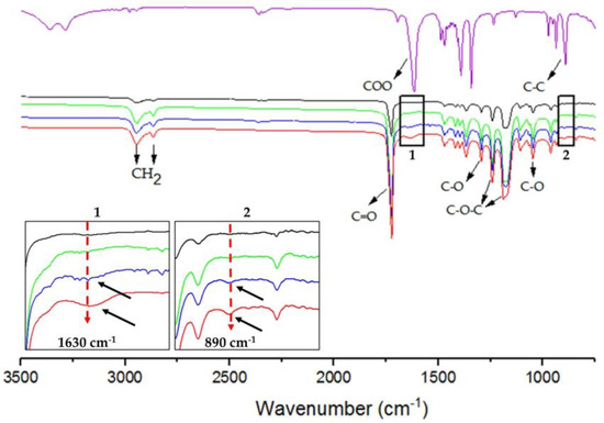
Figure 3.
ATR/FT-IR spectra of (purple) G, (black) P/G0-EPnF, (green) P/G0.5-EPnF, (blue) P/G1-EPnF, and (red) P/G2-EPnF. Insets 1 and 2 show zoomed-in images of the absorption bands of G at 890 cm−1 and 1630 cm−1 for C-C and the carboxylic groups in the P/G- EPnF meshes.
3.2. CA Measurements
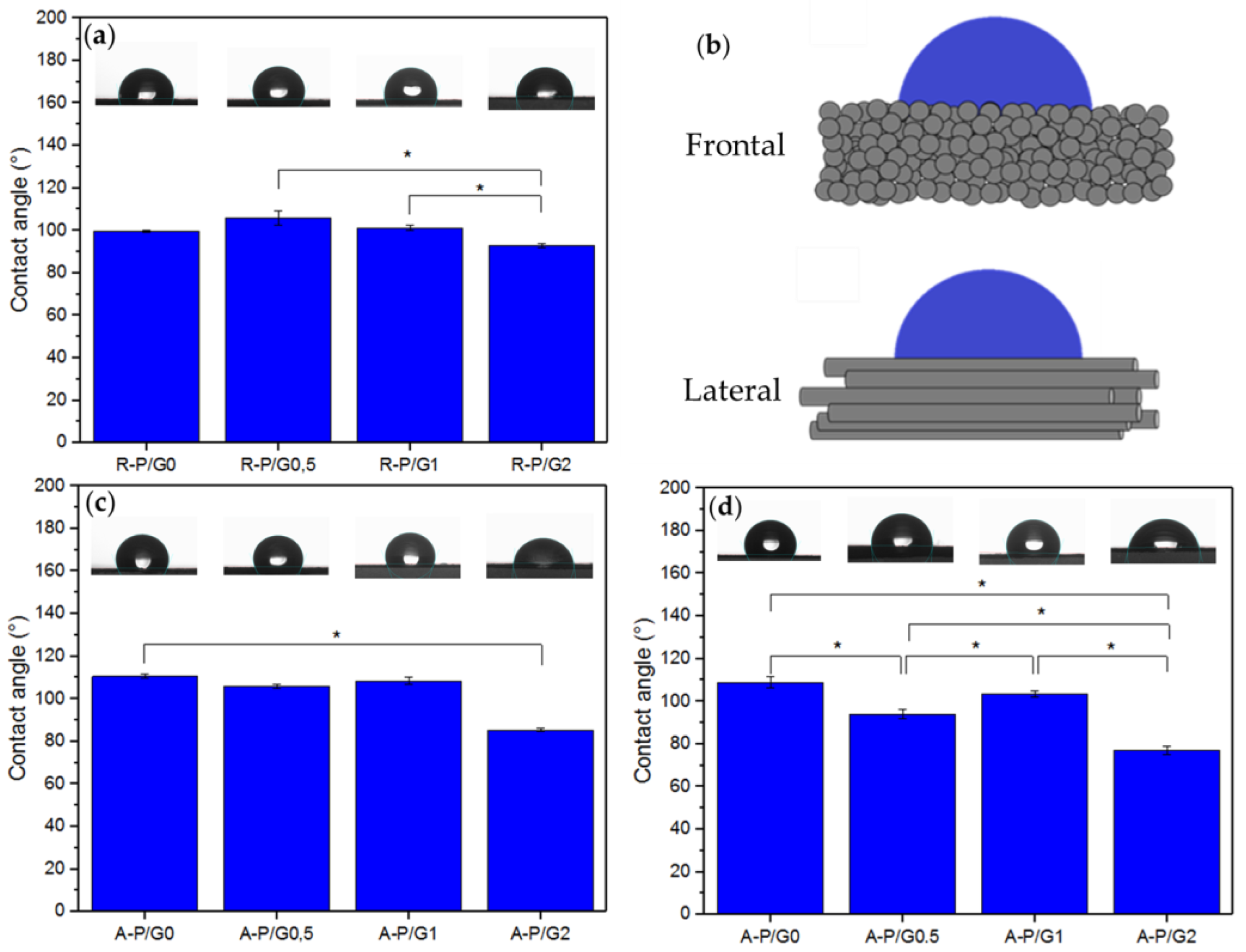
P is a hydrophobic material [16], as was confirmed by the recorded CA values above 110° for R-P/G0-EPnF and A-P/G0-EPnF (Figure 4). A similar behavior was found for R-P/G0.5-EPnF, R-P/G1-EPnF, and R-P/G2-EPnF, the CA values of which were close to 100° (Figure 4a); however, when analyzing the results, it was possible to observe that there were statistically significant differences between the R-P/G1-EPnF and R-P/G2-EPnF groups. For the aligned fibers, CA was measured frontally and laterally (Figure 4b) since a spherical drop cannot be obtained on anisotropic structures [32]. The results (Figure 4c,d) agree with those in previous reports [33], specifically in relation to how the fiber orientation and the measurement method are determinants of CA. In aligned fibers, a similar behavior was seen, where G-concentration-dependence was observed (Figure 4c,d). The increase in the degree of wetting in the meshes containing higher concentrations of G in the P/G-EPnF systems is explained by the ability of G to increase hydrophilicity through its ability to retain water [24]. In the case of aligned fibers, it was also possible to observe an effect attributed to the topography of the substrate. In A-P/G2-EPnF, CA values 20° lower than those in the frontal and lateral measurements of the fibers in the other meshes were observed (Figure 4c,d). However, a higher CA value in A-P/G1-EPnF regarding A-P/G0.5-EPnF in the lateral analysis of the fibers could also be observed (Figure 4d). The present results indicate that CA is also influenced by fiber orientation. This occurs since the wetting degree of a material depends on the surface free energy, which is sensitive to the chemical traits of the material. Therefore, the 20° variation in CA for A-P/G2-EPnF indicates that fiber orientation modulates the surface free energy [11]. These results confirm that CA is dependent on both the fiber orientation and the chemical characteristics of the material.
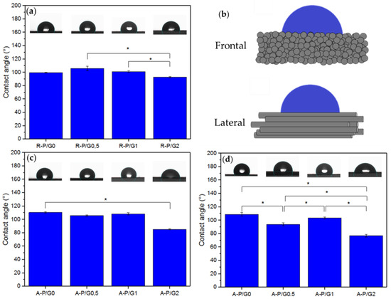
Figure 4.
The static water CA. (a) R-P/G-EPnF, (b) schematic representing the different ways of measuring CA on an anisotropic surface, (c) A-P/G-EPnF obtained frontal to the fibers, and (d) A-P/G-EPnF obtained lateral to the fibers. Asterisk (*) indicates p < 0.05.
3.3. SEM Analysis
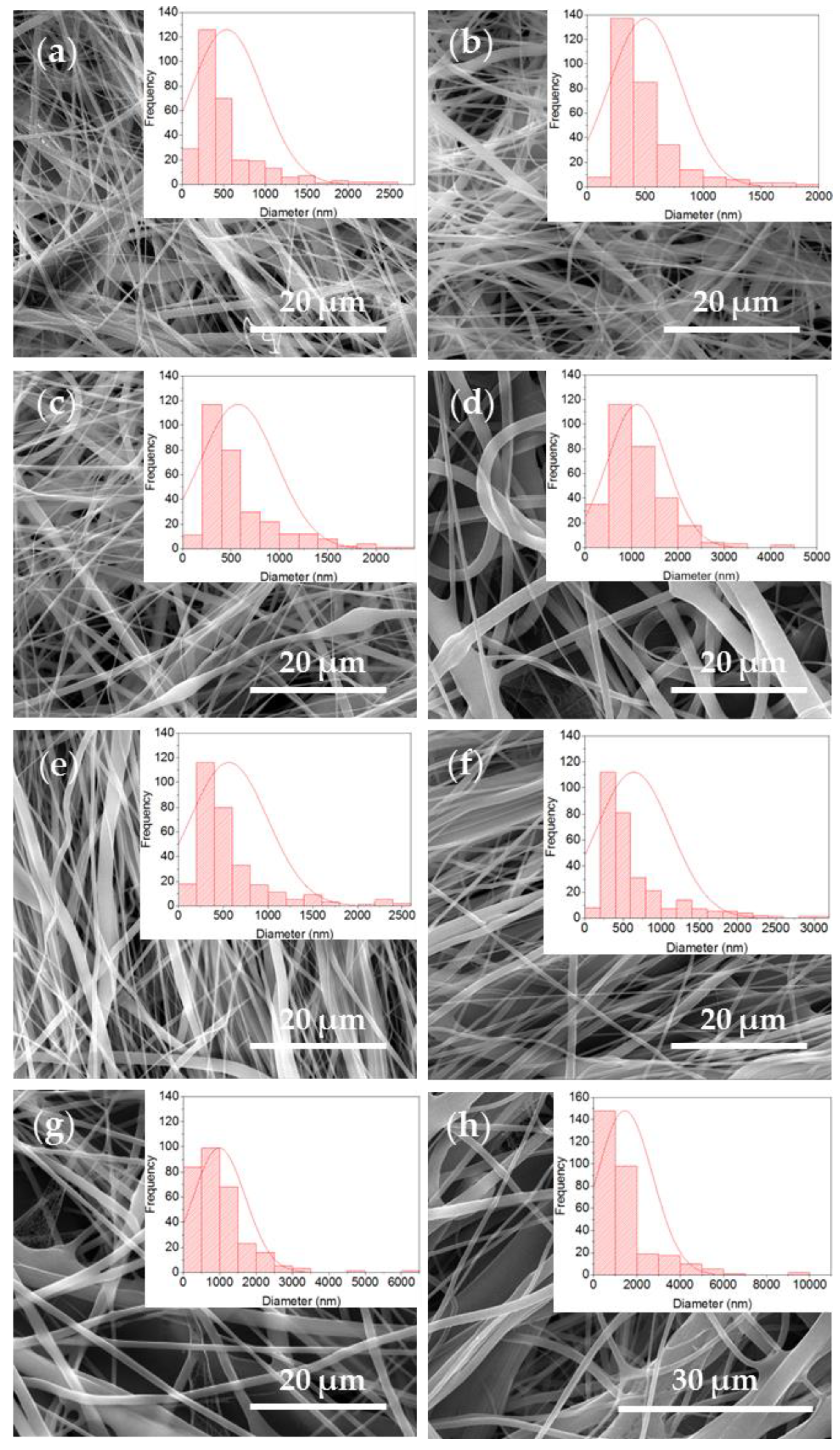
The SEM analysis served to study mesh morphologies. In the micrographs obtained for the different EPnF meshes, it was possible to observe continuous fibers with some defects on their surfaces and the presence of flat fibers. This is attributed to the solvent system used, in which water was incorporated. Previous works have reported the difficulty of manufacturing P 16% fibers in this solvent (acetic acid/ethyl acetate/Milli-Q water) [34]. In this work, it was possible to obtain fibers with nanometer and micrometer diameters (Figure 5 and Figure 6); a similar result has been recently reported [21]. When the rotary collector was used, fibers that were not completely aligned were obtained.
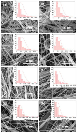
Figure 5.
SEM images and histogram of fiber diameter distribution of the R-P/G-EPnF and A-P/G-EPnF meshes. (a) R-P/G0-EPnF, (b) R-P/G0.5-EPnF, (c) R-P/G1-EPnF, (d) R-P/G2-EPnF, (e) A-P/G0-EPnF, (f) A-P/G0.5-EPnF, (g) A-P/G1-EPnF, and (h) A-P/G2-EPnF.
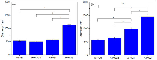
Figure 6.
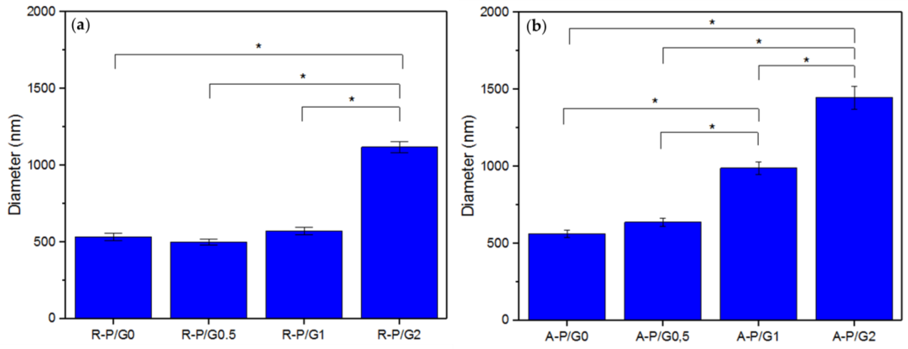
Average fiber diameter of the (a) R-P/G-EPnF meshes obtained with the flat collector and (b) A-P/G-EPnF meshes obtained with the rotary collector. Asterisk (*) indicates p < 0.05.
When evaluating the increasing effect of G in P/G EPnF, an increased fiber diameter was observed. Moreover, in the R-P/G-EPnF meshes, statistically significant differences (p > 0.05) in the fiber diameter were found between R-P/G2-EPnF and the R-P/G0-EPnF, R-P/G0.5-EPnF, and R-P/G1-EPnF groups (Figure 6a). In turn, A-P/G0-EPnF and A-P/G0.5-EPnF behaved similarly, but statistically significant differences (p < 0.05) were observed between these meshes and A-P/G1-EPnF and A-P/G2-EPnF (Figure 6b). When comparing the effects of G concentration, other authors also observed an increase in fiber diameter in poly(ethylene-co-vinyl alcohol) meshes [22]. Finally, in a comparison of the fiber collector effect on fiber diameter, statistical differences (p < 0.05) were obtained (p > 0.05) between R-P/G0.5-EPnF and A-P/G0.5-EPnF and between R-P/G1-EPnF and A-P/G1-EPnF.
These findings indicate that the final fiber diameter depends on both the type of collector used and the chemical composition of the polymer solution used in the electrospinning process. This is because the final traits of the fibers are influenced by environmental factors (temperature and humidity), characteristics of the polymer solution (concentration, polymer, loading, viscosity, conductivity, etc.), and specific parameters of the ES process (voltage, distance, and pressure) [35]. However, there is a fan effect that occurs in the rotating manifold at high speed, which causes the solvent to evaporate faster [10], and when G is added, some characteristics of the polymeric solution change. Therefore, new parameters for the ES process were required, presenting a similar situation to that observed in the CA measurements.
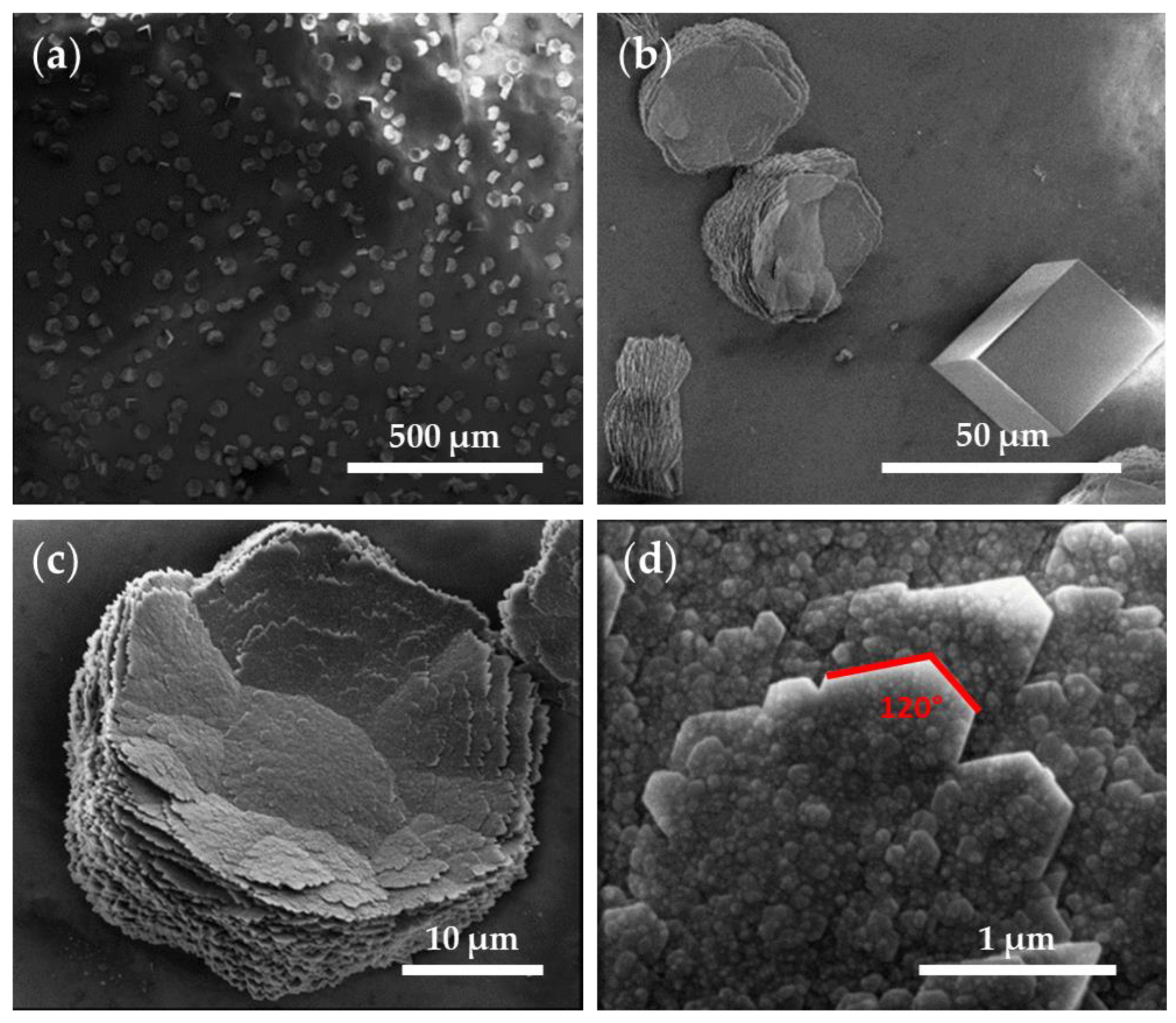
The SEM images of the CaCO3 crystals obtained through GD (Figure 7) showed a homogenous distribution of the crystalline material in the control tests using a glass substrate (Figure 7a). Further observed were rhombohedral structures, corresponding to smooth-surfaced calcite crystals (29.6 ± 8.1 µm), and flower-like hexagonal structures (38 ± 4.8 µm in diameter) formed by stacked flakes (≈70 nm in height) (Figure 7b–d), which correspond to the polymorph vaterite. The surface of the flower-like structures presented a nanogranular texture (38.5 ± 14 nm) (Figure 7d). The crystal boundary ended at 120° angles, indicating that these hexagonal plates correspond to the phase (001) monocrystals of vaterite and the hexagonal boundaries parallel to {110}, as described elsewhere [36]. Although the morphologies of the crystals are quite varied, characteristic morphologies were described for the CaCO3 polymorphs (namely, rhombohedral calcite, needle-like aragonite, and spherical vaterite) [5,36,37,38], and these allowed us to approximate the observed polymorphs using SEM, which were later confirmed using XRD (please see Table 2).
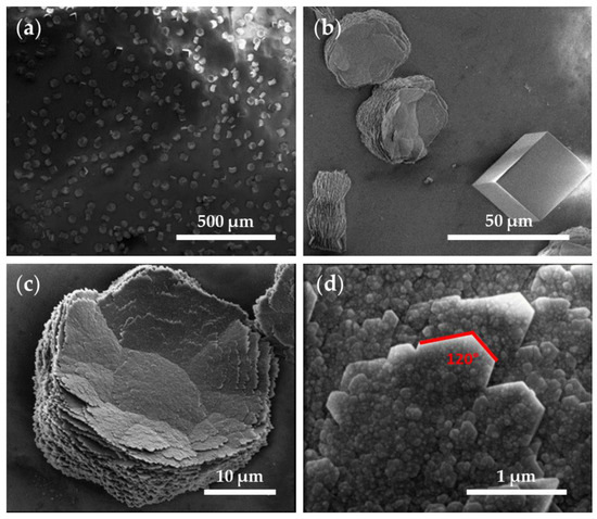
Figure 7.
SEM images of CaCO3 obtained through GD crystallization assays on a glass substrate (control substrate). Magnifications of (a) 200×, (b) 2500×, (c) 7000×, and (d) 100,000×.

Table 2.
Crystal sizes of calcite (C) and vaterite (V) obtained in GD crystallization assays on the R-P/G/CaCO3-EPnF and A-P/G/CaCO3-EPnF meshes using SEM.
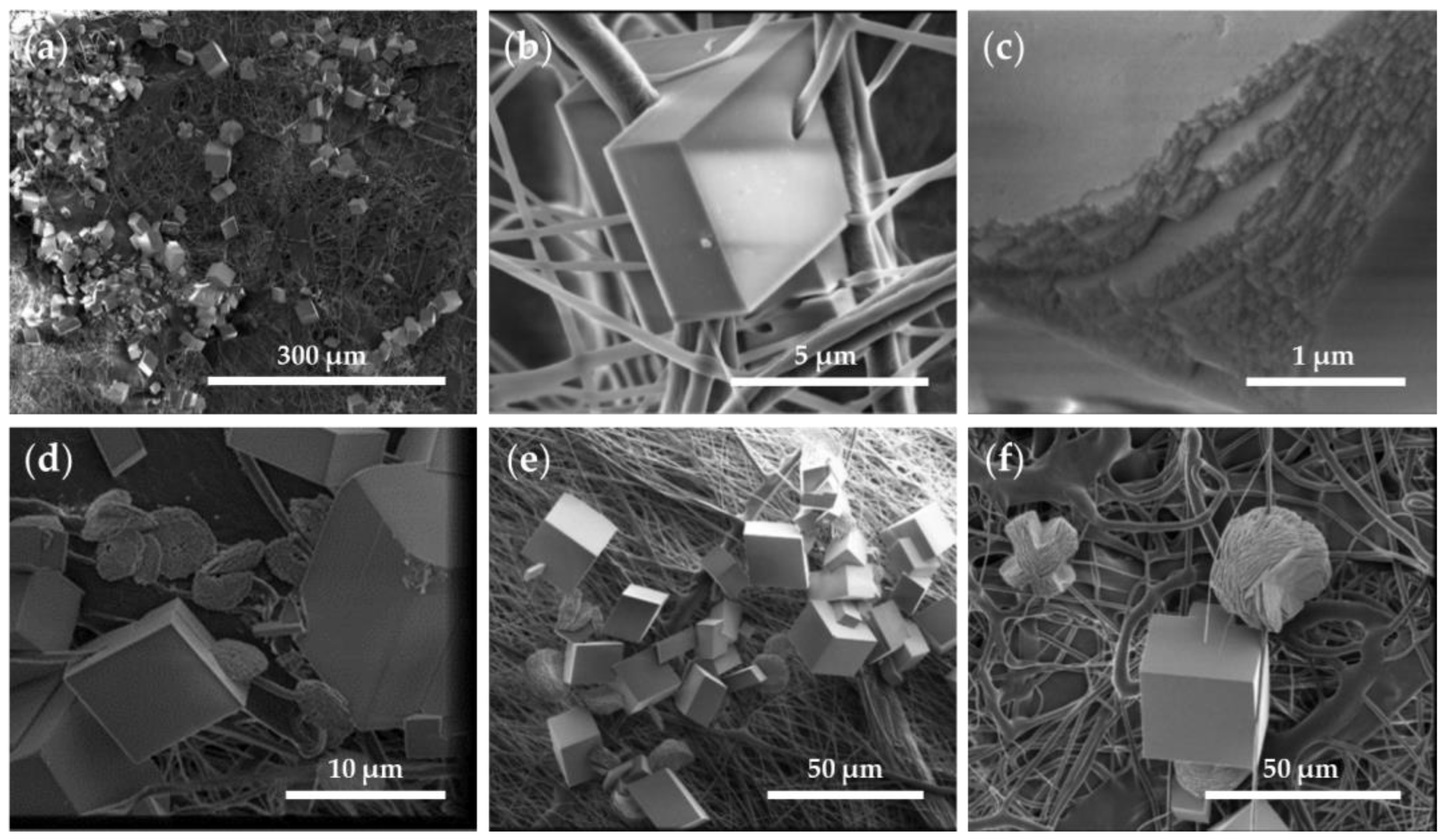
An analysis of the P/G-EPnF and P/G/CaCO3-EPnF meshes revealed that, independent of the fiber orientation and composition of the P/G-EPnF meshes, the crystals were not distributed homogeneously over the matrix. Instead, agglomerates of crystals in different zones were observed, and they decreased the surface energy of the crystals that were smaller due to the presence of a greater number of nucleation centers (Figure 8a) [37]. Furthermore, the CaCO3 crystals closely interacted with proximally growing fibers (Figure 8b). This occurred because there was a geometric match between the functional groups of the organic matrix and the crystal lattice of a specific phase [26,38]. Further found was that both the lattices and respective compositions influenced the process. This is explained by the fact that the environment where mineralization occurs determines the morphology and size of the crystals obtained [7,8]. However, the CaCO3 crystals had defects on the crystalline surface in the presence of meshes (Figure 8c), as opposed to what occurred in the absence of meshes (Figure 7).
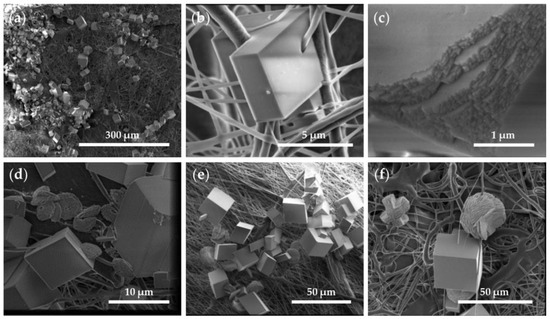
Figure 8.
SEM images of R-P/G0/CaCO3-EPnF and A-P/G0/CaCO3-EPnF. (a) R-P/G2/CaCO3-EPnF, 500× magnification; (b) R-P/G0/CaCO3-EPnF, 25,000× magnification; (c) R-P/G0/CaCO3-EPnF, 50,000× magnification; (d) A-P/G0/CaCO3-EPnF, 10,000× magnification; (e) R-P/G0.5/CaCO3-EPnF, 2000× magnification; and (f) R-P/G2/CaCO3-EPnF, 2500× magnification.
In the control tests (i.e., in the absence of the P/G-EPnF meshes), vaterite and calcite crystals were obtained, as subsequently confirmed using XRD. These results indicate that P/G-EPnF meshes favor the formation of rhombohedral crystals. Although these grow in agglomerates and fuse together, thus preventing counting, it was qualitatively possible to determine the predominance of rhombohedral crystals. Meanwhile, the flower morphology of the vaterite crystals was lost in the P/G0/CaCO3-EPnF lattices, and only a few elliptical crystals were observed. However, in P/G0.5/CaCO3-EPnF, P/G1/CaCO3-EPnF, and P/G2/CaCO3-EPnF, the coexistence of vaterite crystals with flower and elliptical morphologies was observed (Figure 8d–f). Our findings obtained by carrying out SEM and XRD analyses of the crystals show that the topography of the meshes of R-P/G-EPnF and A-P/G-EPnF did not affect the growth of the CaCO3 crystals.
In mineralization, the presence of other ions or the deletion of crystal lattice ions on the crystal surface generates a heterogeneous distribution of energy on the crystal surface, thereby impacting the rate of crystal growth [2,37,39,40]. This was evidenced by alterations on the crystal surface (Figure 8c) and by comparing crystal size. The CaCO3 crystals obtained on P/G0/CaCO3-EPnF were six times smaller than the crystals observed on the glass substrates, while the crystals obtained on P/G0.5/CaCO3-EPnF, P/G1/CaCO3-EPnF, and P/G2/CaCO3-EPnF were three to four times smaller than those obtained on the control. These did, however, increase in size with increasing G concentrations in the mesh (Table 2). Previous experiments on the CaCO3 crystals in electrospun P meshes show that fiber distribution influences nucleation and the calcite-to-vaterite ratio [28].
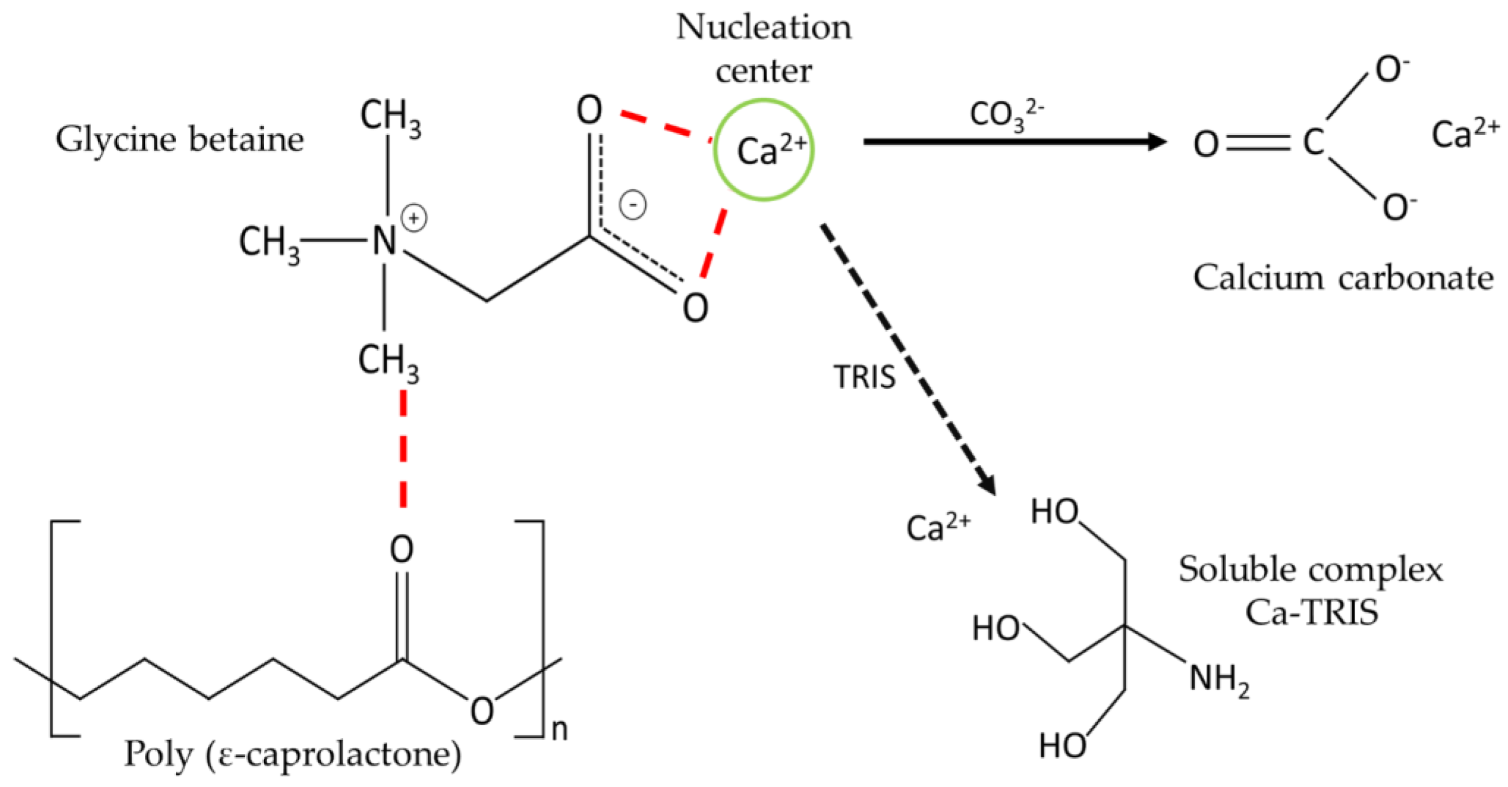
The presence of new functional groups on the substrate favors the formation of nucleation centers [3]. This situation is similar to that which occurs in nanocellulose, where it acts as a scaffold for CaCO3 growth [8], as determined by the presence of hydroxyl groups of nanocellulose that interact with Ca2+ ions causing modifications in the speed and direction of growth, ultimately altering the final morphology of calcite crystals. These authors indicate that nanocellulose, due to electrostatic interactions and the steric effect, prevents the sustained growth of the crystals, generating a decrease in the crystalline size because the nanocellulose interacts with specific crystalline phases, thereby preventing or delaying the vertical growth of that phase, which consequently remains stable. Therefore, in this work, it is proposed that Ca2+ is attracted by the carboxylate group of the G molecule, favoring the presence of new nucleation centers (Figure 9).
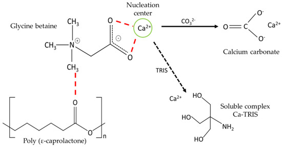
Figure 9.
Schematic representation of the interaction between P, G, TRIS, and Ca2+.
However, it has been described that the TRIS buffer used in CaCO3 crystallization assays could influence crystalline growth by forming soluble complexes with Ca2+ ions, decreasing their availability in the medium [41,42,43]. Therefore, the presence of TRIS is essential to maintain the pH of a crystallization solution at pH 9. It is important to note that the concentration of TRIS was not varied in the different crystallization tests, which is why it does not represent a new variable in our results. Moreover, its concentration can be considered negligible in this assay.
3.4. XRD Analysis
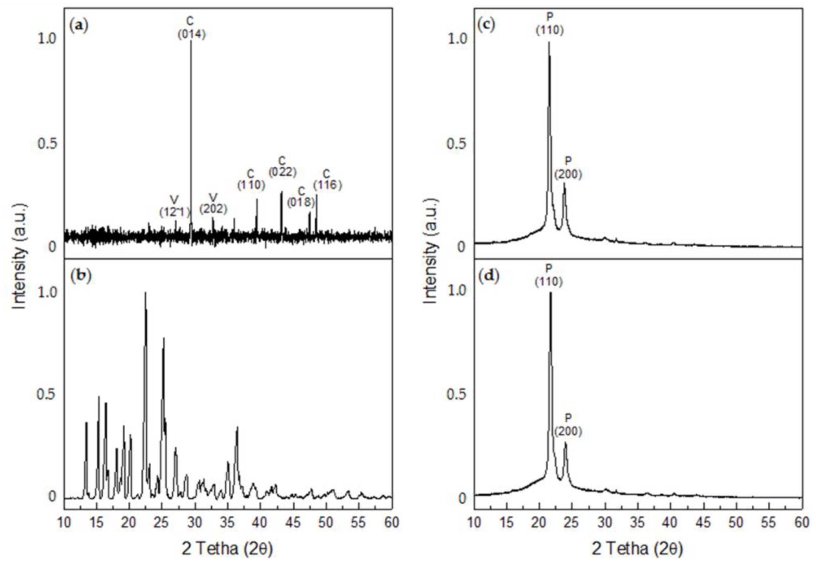
X-ray diffraction determined that the CaCO3 crystals obtained in the control tests corresponded to calcite, with crystalline peaks at 2θ 29.4° (014), 39.4° (113), 43.1° (022), 47.4° (018), and 48.5° (116) (COD #2100992), and to vaterite, with 2θ crystalline peaks at 27° (12-1) and 32.7° (202) (COD #9014701) (Figure 10a). Most of the crystals formed were calcite, which represents 67.1% of the sample, while vaterite represents 32.9% of the sample. In turn, numerous peaks were observed for the XDR of G, the most intense of which occurred at 2θ angles of 15.3°, 22.5°, and 25.18° (PDF #13-0815) (Figure 10b). For the P/G0-EPnF mesh, the XRD of R-P/G0-EPnF identified the presence of most characteristic crystalline peaks at 2θ 21.3° and 23.6°, which correspond to the crystallographic planes (110) and (200), respectively [44] (Figure 10c). When analyzing the diffractogram of P/G2-EPnF, only the crystallographic peaks associated with P appeared (Figure 10d). This could be due to the interaction of G with P during the electrospinning process, which could cause the G crystalline structure loss [45]. The random and aligned fibers of P/G-EPnF had the same XRD pattern, so the diffractograms of R-P/G0-EPnF and R-P/G2-EPnF are reported in Figure 10.
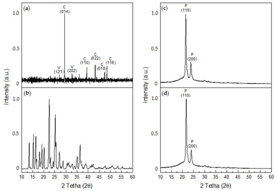
Figure 10.
XRD diffractograms. (a) CaCO3, (b) glycine betaine, (c) R-P/G0-EPnF, and (d) R-P/G2-EPnF. The abbreviations of C, V, and P correspond to calcite, vaterite, and poly (ε-caprolactone), respectively.
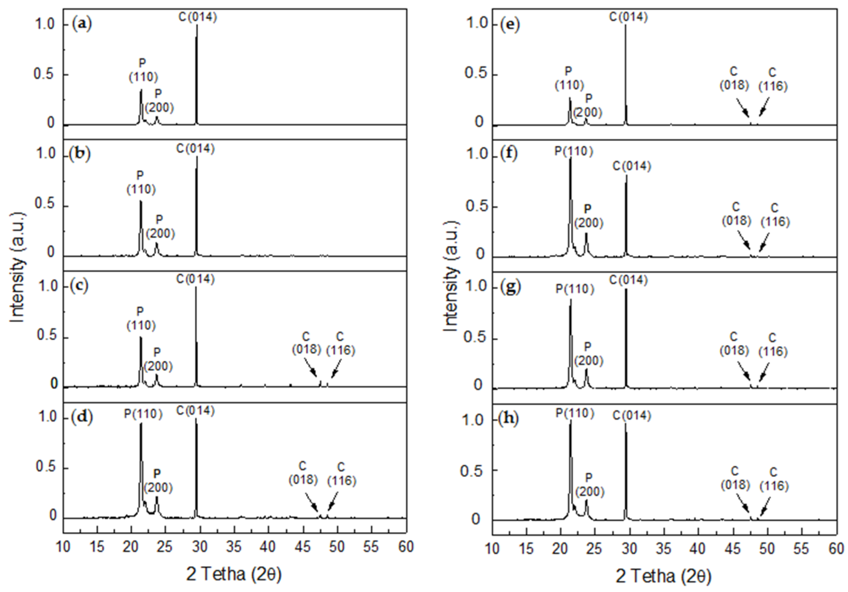
An analysis of the XRD diffractograms for the R-P/G-EPnF (Figure 11a–d) and A-P/G-EPnF (Figure 11e–h) meshes used as substrates in the GD crystallization tests revealed the typical crystalline peaks associated with P in all samples and the presence of calcite. Although hexagonal crystals of vaterite were observed, its abundance was lower than that of calcite, thus explaining the absence of crystallographic peaks for this or other polymorphs that could be present in the meshes. This was confirmed by a Rietveld analysis, where it was shown that the composition of the samples was 100% calcite, with the exception of A-P/G0.5-EPnF, which had a composition of 97.4% calcite and only 2.6% vaterite. Therefore, our experimental findings demonstrate the stabilization almost exclusively of calcite in the P/G-EPnF electrospun meshes, independent of their composition. However, the crystallite sizes of calcite and vaterite are modified depending on the substrate where the crystallization takes place. This behavior is not associated with the topography of the substrate, but there is a relationship in terms of the concentration of G in the meshes. In Table 3, we can see that, in both R-P/G-EPnF and A-P/G-EPnF, there is a decrease in crystallite size at concentrations of 0.5 and 2% G.
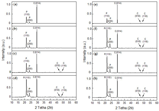
Figure 11.
XRD diffractograms of CaCO3 obtained for GD assays on R-P/G-EPnF and A-P/G-EPnF meshes. (a) R-P/G0-EPnF, (b) R-P/G0.5-EPnF, (c) R-P/G1-EPnF, (d) R-P/G2-EPnF, (e) A-P/G0-EPnF, (f) A-P/G0.5-EPnF, (g) A-P/G1-EPnF, and (h) A-P/G2-EPnF. The abbreviations of P, C, and V correspond to polycaprolactone, calcite, and vaterite, respectively.

Table 3.
Crystallite sizes of calcite (C) and vaterite (V) obtained in GD crystallization assays on the R-P/G/CaCO3-EPnF and A-P/G/CaCO3-EPnF meshes determined using XRD.
Additionally, various crystallographic peaks associated with calcite were detected in both P/G-EPnF systems (Figure 11c–h); however, the 2θ crystallographic peaks that appeared at 43.1° and 47.5° were not observed in R-P/G0-EPn or R-P/G0.5-EPnF (Figure 11a,b).
This could be explained by the interaction of the organic matrix with certain crystalline phases preventing or delaying growth, as mentioned above. Nevertheless, this does not mean that the interaction prevents the growth of other crystalline phases associated with the same polymorph [8].
The Rietveld refinement method was carried out using the Scherer method, through which it was possible to determine the crystallite sizes of the crystals obtained in the samples (Table 3), where the sizes of the crystallites for calcite (C) had a similar behavior with both mesh topographies. The Rietveld analysis showed the largest crystallite sizes for the control and both fibrillar systems R-P/G and A-P/G in the absence of G. Thus, this analysis showed that the concentration of G1 in both fibrillar mesh systems (P/G1-EPnF) presented the largest crystallite sizes, and the crystallite size of vaterite (V) in the A-P/G-EPnF system was 89 nm, identical to that in the control assay. However, the size of the crystallites did not correlate with the increase in the diameter of the fibers observed using SEM when increasing the concentration of G in both fibrillar systems. The crystalline cell parameters of each assay are reported in Table 4.

Table 4.
Unit cell volume and quantitative analysis of crystal structure and phase of CaCO3.
3.5. TGA/DTG Analysis
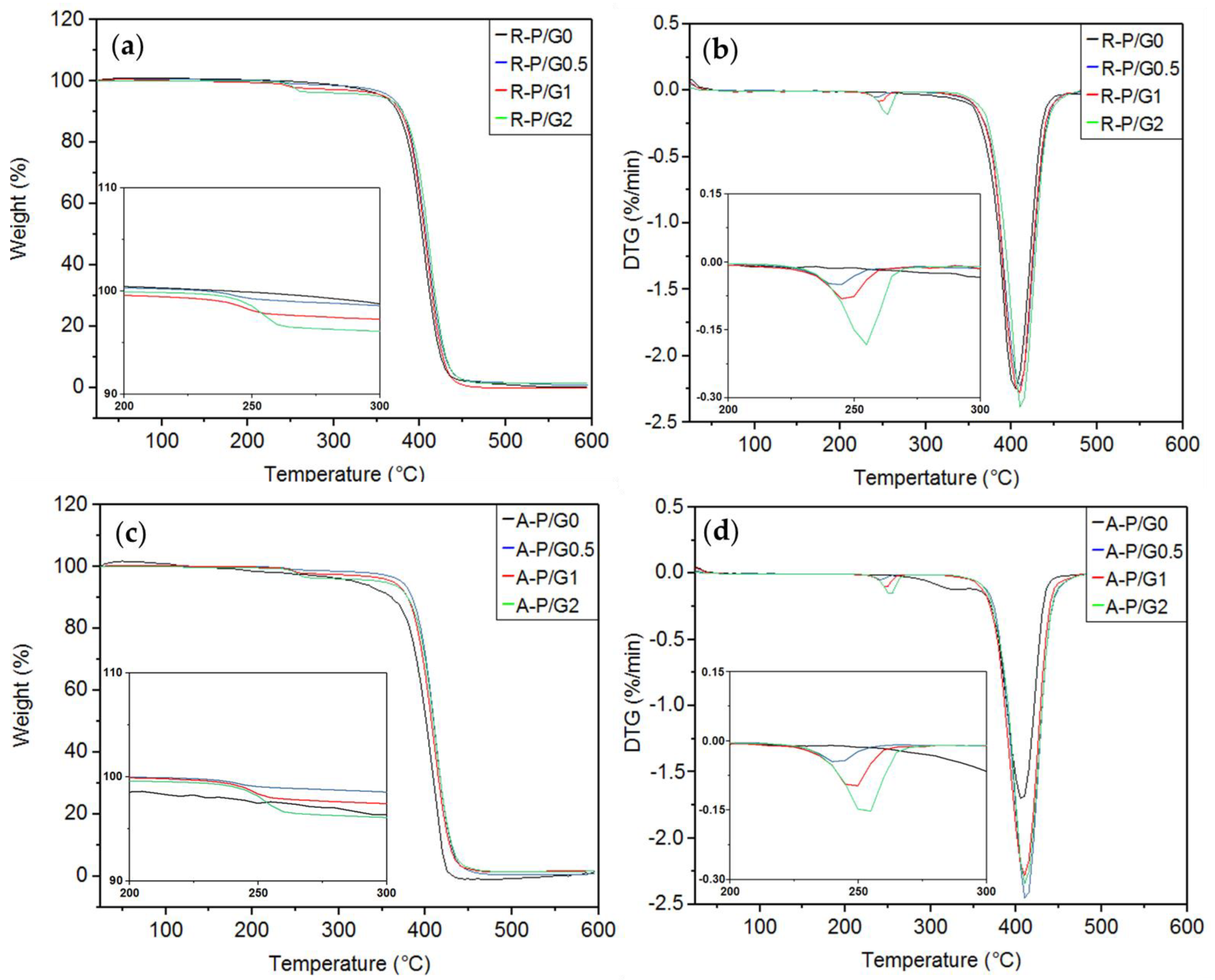
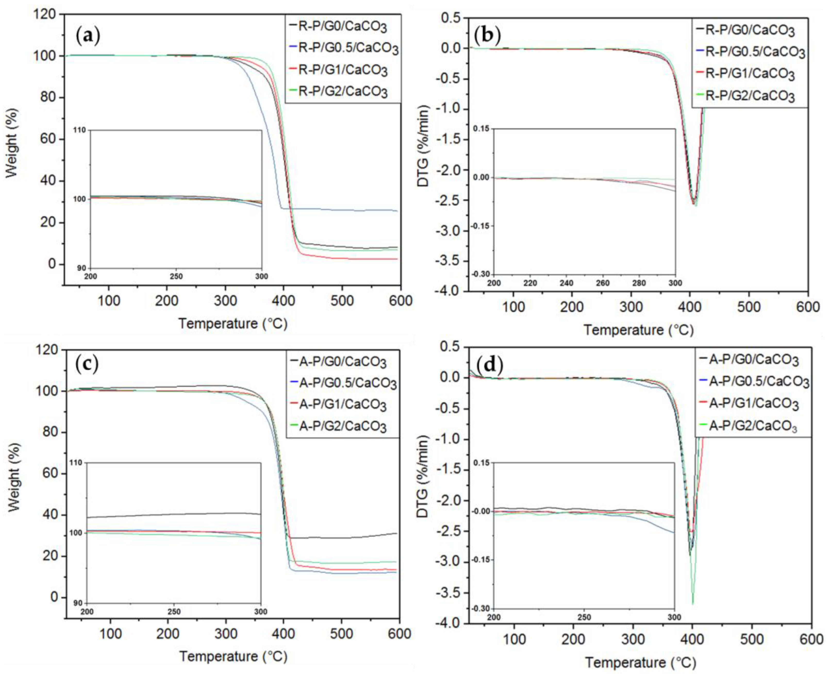
TGA/DTG assess the thermal stability of materials. In the present study, no differences were observed between R-P/G0-EPnF and A-P/G0-EPnF (Table 5 and Figure 12). It has been described that the decomposition temperature of P is 400 °C [46], while that for G is close to 300°C [25,47,48]. The thermal decomposition behaviors of R-P/G0-EPnF and A-P/G0-EPnF were 408 °C and 407 °C, respectively. In the meshes containing G, two decomposition processes were observed, one near 400 °C (associated with P) and another at 250 °C (attributable to the presence of G).

Table 5.
TGA of R-P/G-EPnF and A-P/G-EPnF meshes.
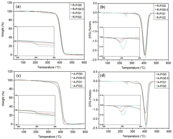
Figure 12.
TGA and DTG curves for the R-P/G-EPnF and A-P/G-EPnF meshes. (a) TGA of R-P/G-EPnF, (b) DTG of the R-P/G-EPnF meshes, (c) TGA of the A-P/G-EPnF meshes, and (d) DTG of A-P/G-EPnF.
These results show a pattern in the thermal decomposition process, with a slight increase in the decomposition temperatures of G and P depending on the concentration of G in the meshes. In another study, when G was incorporated into poly(vinyl alcohol) meshes, as the decomposition temperature of poly(vinyl alcohol) decreased, the thermal stability of G increased [25]. This prior study demonstrates an interaction between poly(vinyl alcohol) and G that modifies thermal stability and that is dependent on the G concentration. Differences in behavior as compared to the present study, where the decomposition temperature of both materials increased, could be attributable to the existing specific interaction between materials.
The results for the TGAs of R-P/G-EPnF and A-P/G-EPnF after the crystallization tests are summarized in Table 6 and Figure 13. Only one thermal decomposition process of the organic–inorganic hybrid meshes was close to 400 °C, as it was associated with the decomposition temperature of P. However, when comparing the mass loss of the meshes in the absence of crystals, those containing CaCO3 showed a lower mass loss. This could be associated with the mineral component in the mesh having a decomposition temperature higher than 700 °C [8,49].

Table 6.
TGA of R-P/G/CaCO3-EPnF and A-P/G/CaCO3-EPnF hybrid meshes.
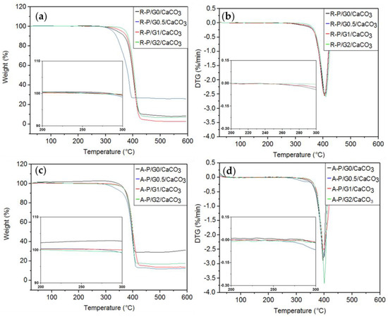
Figure 13.
TGA and DTG curves for the R-P/G/CaCO3-EPnF and A-P/G/CaCO3-EPnF hybrid meshes. (a) TGA of R-P/G/CaCO3-EPnF, (b) DTG of R-P/G/CaCO3-EPnF meshes, (c) TGA of A-P/G/CaCO3-EPnF meshes, and (d) DTG of A-P/G/CaCO3-EPnF meshes.
Importantly, an initial decomposition process near 250 °C was not observed in P/G/CaCO3-EPnF but was observed in P/G-EPnF. This can be explained by the interaction between Ca2+ and G, which sustains incorporation into the crystalline matrix. In this work, it was hypothesized that the positively charged tetramethyl-ammonium group of G interacts with the carbonyl group of P through electrostatic interactions; this exposes the negatively charged carboxylate group of the G molecule, which has the ability to attract Ca2+, forming a nucleation center explaining the incorporation of P/G-EPnF meshes. This allows the organic part to be incorporated into the crystalline matrix [37,50,51], which explains the close relationship between the fibers and the crystals that was observed using SEM.
As has been shown elsewhere [52], similar findings using organic–inorganic materials demonstrated that CaCO3 acts as a crosslinking agent between the proteins within the organic component, thereby improving the mechanical properties of the prepared hybrid material. Additionally, similar results were also reported when forming a unique, distinctive organic–inorganic material, with new properties given by the interaction between CaCO3 and the functional groups of the organic matrix [8].
4. Conclusions
A topography-controlled organic–inorganic P/G/CaCO3-EPnF hybrid material was obtained using electrospun R-P/G/-EPnF and A-P/G/-EPnF matrices and the application of ES and the CaCO3 GD crystallization technique. The incorporation of G (0.5, 1, and 2% w/v) into these meshes influenced the fiber diameter without altering the mechanical properties. A thermal gravimetric analysis indicated the presence of a single thermal decomposition process in P/G/CaCO3-EPnF, suggesting the incorporation of G into the crystalline matrix. Such incorporation demonstrates the formation of a new organic–inorganic hybrid material that has significant potential for use in biomedicine due to the properties and characteristics of each material of the fibrillar system. Therefore, the P/G/CaCO3-EPnF hybrid material could potentiate the characteristics of each of the components that compose it.
Author Contributions
N.B.-M.: conceptualization, methodology, investigation, and writing—original draft. A.N.-C.: conceptualization, methodology, investigation, writing—original draft, and writing—review and editing. A.I.: conceptualization, methodology, and writing—review and editing. G.C.-B.: conceptualization and writing—review and editing. All authors have read and agreed to the published version of the manuscript.
Funding
PhD student: N.B.-M. is grateful for the funding provided by the Chilean Agency for Research and Development (ANID) doctorate scholarship No. 21191212. This study was financially supported by the Chilean Agency for Research and Development (ANID) through the Fondecyt No. 1211345 grant. We thank the ACCDiS center (funded through Fondap No. 15130011) for technical assistance.
Data Availability Statement
Data can be provided on the request from the corresponding author.
Acknowledgments
A.N.-C. is grateful for the Fondecyt No. 1211345 project and thanks the ACCDiS center (Fondap No. 15130011) for technical assistance. N.B.-M. is grateful for the ANID scholarship No. 21191212.
Conflicts of Interest
The authors declare no conflict of interest.
References
- Zhao, P.; Tian, Y.; You, J.; Hu, X.; Liu, Y. Recent Advances of Calcium Carbonate Nanoparticles for Biomedical Applications. Bioengineering 2022, 9, 691. [Google Scholar] [CrossRef] [PubMed]
- Morse, J.W.; Arvidson, R.S.; Lüttge, A. Calcium Carbonate Formation and Dissolution. Chem. Rev. 2007, 107, 342–381. [Google Scholar] [CrossRef]
- Voronova, M.I.; Surov, O.V.; Lebedeva, E.O.; Rubleva, N.V.; Afineevskii, A.V.; Zakharov, A.G. Calcium Carbonate Mineralization in Polycaprolactone Composites with Nanocrystalline Cellulose: Structure, Morphology, and Adsorption Properties. Russ. J. Inorg. Chem. 2021, 66, 1904–1916. [Google Scholar] [CrossRef]
- Saveleva, M.S.; Ivanov, A.N.; Kurtukova, M.O.; Atkin, V.S.; Ivanova, A.G.; Lyubun, G.P.; Martyukova, A.V.; Cherevko, E.I.; Sargsyan, A.K.; Fedonnikov, A.S.; et al. Hybrid PCL/CaCO3 Scaffolds with Capabilities of Carrying Biologically Active Molecules: Synthesis, Loading and in Vivo Applications. Mater. Sci. Eng. C 2018, 85, 57–67. [Google Scholar] [CrossRef] [PubMed]
- Boyjoo, Y.; Pareek, V.K.; Liu, J. Synthesis of Micro and Nano-Sized Calcium Carbonate Particles and Their Applications. J. Mater. Chem. A Mater. 2014, 2, 14270–14288. [Google Scholar] [CrossRef]
- Von Euw, S.; Zhang, Q.; Manichev, V.; Murali, N.; Gross, J.; Feldman, L.C.; Gustafsson, T.; Flach, C.; Mendelsohn, R.; Falkowski, P.G. Biological Control of Aragonite Formation in Stony Corals. Science 2017, 356, 933–938. [Google Scholar] [CrossRef]
- Jiang, W.; Pacella, M.S.; Athanasiadou, D.; Nelea, V.; Vali, H.; Hazen, R.M.; Gray, J.J.; McKee, M.D. Chiral Acidic Amino Acids Induce Chiral Hierarchical Structure in Calcium Carbonate. Nat. Commun. 2017, 8, 15066. [Google Scholar] [CrossRef]
- Lu, Q.; Cai, Z.; Wang, S.; Lin, F.; Lu, B.; Chen, Y.; Huang, B. Controlled Construction of Nanostructured Organic-Inorganic Hybrid Material Induced by Nanocellulose. ACS Sustain. Chem. Eng. 2017, 5, 8456–8463. [Google Scholar] [CrossRef]
- Zadehnajar, P.; Karbasi, S.; Akbari, B.; Ghasemi, L. Incorporation of Multi-Walled Carbon Nanotubes into Electrospun PCL/Gelatin Scaffold: The Influence on the Physical, Chemical and Thermal Properties and Cell Response for Tissue Engineering. Mater. Technol. 2020, 35, 39–49. [Google Scholar] [CrossRef]
- Mirjalili, M.; Zohoori, S. Review for Application of Electrospinning and Electrospun Nanofibers Technology in Textile Industry. J. Nanostruct. Chem. 2016, 6, 207–213. [Google Scholar] [CrossRef]
- Szewczyk, P.K.; Ura, D.P.; Metwally, S.; Knapczyk-Korczak, J.; Gajek, M.; Marzec, M.M.; Bernasik, A.; Stachewicz, U. Roughness and Fiber Fraction Dominated Wetting of Electrospun Fiber-Based Porous Meshes. Polymers. 2019, 11, 34. [Google Scholar] [CrossRef]
- Mokhtari, F.; Salehi, M.; Zamani, F.; Hajiani, F.; Zeighami, F.; Latifi, M. Advances in Electrospinning: The Production and Application of Nanofibres and Nanofibrous Structures. Text. Prog. 2016, 48, 119–219. [Google Scholar] [CrossRef]
- Ye, K.; Kuang, H.; You, Z.; Morsi, Y.; Mo, X. Electrospun Nanofibers for Tissue Engineering with Drug Loading and Release. Pharmaceutics. 2019, 11, 182. [Google Scholar] [CrossRef] [PubMed]
- Metwally, S.; Ferraris, S.; Spriano, S.; Krysiak, Z.J.; Kaniuk, Ł.; Marzec, M.M.; Kim, S.K.; Szewczyk, P.K.; Gruszczyński, A.; Wytrwal-Sarna, M.; et al. Surface Potential and Roughness Controlled Cell Adhesion and Collagen Formation in Electrospun PCL Fibers for Bone Regeneration. Mater. Des. 2020, 194, 108915. [Google Scholar] [CrossRef]
- Stachewicz, U.; Stone, C.A.; Willis, C.R.; Barber, A.H. Charge Assisted Tailoring of Chemical Functionality at Electrospun Nanofiber Surfaces. J. Mater. Chem. 2012, 22, 22935–22941. [Google Scholar] [CrossRef]
- Chakrapani, V.Y.; Gnanamani, A.; Giridev, V.R.; Madhusoothanan, M.; Sekaran, G. Electrospinning of Type i Collagen and PCL Nanofibers Using Acetic Acid. J. Appl. Polym. Sci. 2012, 125, 3221–3227. [Google Scholar] [CrossRef]
- Zhang, C.L.; Yu, S.H. Nanoparticles Meet Electrospinning: Recent Advances and Future Prospects. Chem. Soc. Rev. 2014, 43, 4423–4448. [Google Scholar] [CrossRef]
- Pant, H.R.; Bajgai, M.P.; Nam, K.T.; Seo, Y.A.; Pandeya, D.R.; Hong, S.T.; Kim, H.Y. Electrospun Nylon-6 Spider-Net like Nanofiber Mat Containing TiO2 Nanoparticles: A Multifunctional Nanocomposite Textile Material. J. Hazard. Mater. 2011, 185, 124–130. [Google Scholar] [CrossRef]
- Ahmadpoor, P.; Nateri, A.S.; Motaghitalab, V. The Optical Properties of PVA/TiO2 Composite Nanofibers. J. Appl. Polym. Sci. 2013, 130, 78–85. [Google Scholar] [CrossRef]
- Khattab, T.A.; Tolba, E.; Gaffer, H.; Kamel, S. Development of Electrospun Nanofibrous-Walled Tubes for Potential Production of Photoluminescent Endoscopes. Ind. Eng. Chem. Res. 2021, 60, 10044–10055. [Google Scholar] [CrossRef]
- Sivakumar, S.; Schmid, R.; Wieland, A.; Strissel, P.L.; Strick, R.; Fischer, L.; Thievessen, I.; Kataev, E.; Arkudas, A.; Horch, R.E.; et al. Role of Fiber Thickness and Surface Treatment of Electrospun Polycaprolactone Matrices on the Growth of Different Breast Cancer-Associated Cells. Adv. Mater. Interfaces. 2022, 9, 2101808. [Google Scholar] [CrossRef]
- Mayuri, P.V.; Bhatt, A.; Ramesh, P. Glycine Integrated Zwitterionic Hemocompatible Electrospun Poly (Ethylene-Co-Vinyl Alcohol) Membranes for Leukodepletion. Biomed. Phys. Eng. Express. 2020, 6, 055019. [Google Scholar] [CrossRef]
- Li, T.; Cui, Y.; Mathaga, J.; Kumar, R.; Kuroda, D.G. Hydration and Vibrational Dynamics of Betaine (N,N,N-Trimethylglycine). J. Chem. Phys. 2015, 142, 212438. [Google Scholar] [CrossRef]
- Moideen K, I.; Isloor, A.M.; Garudachari, B.; Ismail, A.F. The Effect of Glycine Betaine Additive on the PPSU/PSF Ultrafiltration Membrane Performance. Desalin. Water Treat. 2016, 57, 24788–24798. [Google Scholar] [CrossRef]
- Abdollahzadeh, Z.; Honarvar, M.; Ghavami, M. Modeling the Release of Betaine Extracted from Sugar Beet Molasses in the Structure of Fast-Dissolving Electrospun Fibers of Plantago Ovata Seed Gum. Food Biophys. 2022, 17, 448–459. [Google Scholar] [CrossRef]
- Pastero, L.; Aquilano, D. Calcium Carbonate Polymorphs Growing in the Presence of Sericin: A New Composite Mimicking the Hierarchic Structure of Nacre. Crystals 2018, 8, 263. [Google Scholar] [CrossRef]
- Savelyeva, M.S.; Abalymov, A.A.; Lyubun, G.P.; Vidyasheva, I.V.; Yashchenok, A.M.; Douglas, T.E.L.; Gorin, D.A.; Parakhonskiy, B.V. Vaterite Coatings on Electrospun Polymeric Fibers for Biomedical Applications. J. Biomed. Mater. Res. A. 2017, 105, 94–103. [Google Scholar] [CrossRef] [PubMed]
- Sepúlveda, F.; Butto, N.; Arias, J.L.; Yazdani-Pedram, M.; Szewczyk, P.K.; Gruszczynski, A.; Stachewicz, U.; Neira-Carrillo, A. Effect of Porous and Nonporous Polycaprolactone Fiber Meshes on CaCO3Crystallization through a Gas Diffusion Method. Cryst. Growth. Des. 2020, 20, 5610–5625. [Google Scholar] [CrossRef]
- Neira-Carrillo, A.; Acevedo, D.F.; Miras, M.C.; Barbero, C.A.; Gebauer, D.; Cölfen, H.; Arias, J.L. Influence of Conducting Polymers Based on Carboxylated Polyaniline on in Vitro CaCO3 Crystallization. Langmuir 2008, 24, 12496–12507. [Google Scholar] [CrossRef]
- Viertorinne, M.; Valkonen, J.; Pitkänen, I.; Mathlouthi, M.; Nurmi, J. Crystal and Molecular Structure of Anhydrous Betaine, (CH3)3NCH2CO2. J. Mol. Struct. 1999, 477, 23–29. [Google Scholar] [CrossRef]
- Elzein, T.; Nasser-Eddine, M.; Delaite, C.; Bistac, S.; Dumas, P. FTIR Study of Polycaprolactone Chain Organization at Interfaces. J Colloid. Interface Sci. 2004, 273, 381–387. [Google Scholar] [CrossRef]
- Meng, X.L.; Wan, L.S.; Xu, Z.K. Insights into the Static and Advancing Water Contact Angles on Surfaces Anisotropised with Aligned Fibers: Experiments and Modeling. Colloids Surf. A Physicochem. Eng. Asp. 2011, 389, 213–221. [Google Scholar] [CrossRef]
- Kai, D.; Prabhakaran, M.P.; Jin, G.; Ramakrishna, S. Guided Orientation of Cardiomyocytes on Electrospun Aligned Nanofibers for Cardiac Tissue Engineering. J. Biomed. Mater. Res. B Appl. Biomater. 2011, 98B, 379–386. [Google Scholar] [CrossRef]
- Binulal, N.S.; Natarajan, A.; Menon, D.; Bhaskaran, V.K.; Mony, U.; Nair, S.V. PCL-Gelatin Composite Nanofibers Electrospun Using Diluted Acetic Acid-Ethyl Acetate Solvent System for Stem Cell-Based Bone Tissue Engineering. J. Biomater. Sci. Polym. Ed. 2014, 25, 325–340. [Google Scholar] [CrossRef] [PubMed]
- Angammana, C.J.; Jayaram, S.H. Fundamentals of Electrospinning and Processing Technologies. Part. Sci. Technol. 2016, 34, 72–82. [Google Scholar] [CrossRef]
- Hu, Q.; Zhang, J.; Teng, H.; Becker, U. Growth Process and Crystallographic Properties of Ammonia-Induced Vaterite. Am. Mineral. 2012, 97, 1437–1445. [Google Scholar] [CrossRef]
- Liang, P.; Zhao, Y.; Shen, Q.; Wang, D.; Xu, D. The Effect of Carboxymethyl Chitosan on the Precipitation of Calcium Carbonate. J. Cryst. Growth. 2004, 261, 571–576. [Google Scholar] [CrossRef]
- Mann, S. Molecular Recognition in Biomineralization. Nature 1988, 322, 119–124. [Google Scholar] [CrossRef]
- Ehrlich, H.; Koutsoukos, P.G.; Demadis, K.D.; Pokrovsky, O.S. Principles of Demineralization: Modern Strategies for the Isolation of Organic Frameworks. Part II. Decalcification. Micron 2009, 40, 169–193. [Google Scholar] [CrossRef]
- Saharay, M.; Kirkpatrick, R.J. Ab Initio and Metadynamics Studies on the Role of Essential Functional Groups in Biomineralization of Calcium Carbonate and Environmental Situations. Phys. Chem. Chem. Phys. 2014, 16, 26843–26854. [Google Scholar] [CrossRef]
- Miyazaki, T.; Arii, T.; Shirosaki, Y. Control of Crystalline Phase and Morphology of Calcium Carbonate by Electrolysis: Effects of Current and Temperature. Ceram. Int. 2019, 45, 14039–14044. [Google Scholar] [CrossRef]
- Lee, J.H.; Madden, A.S.; Kriven, W.M.; Tas, A.C. Synthetic Aragonite (CaCO 3 ) as a Potential Additive in Calcium Phosphate Cements: Evaluation in Tris-Free SBF at 37 °C. J. Am. Ceram. Soc. 2014, 97, 3052–3061. [Google Scholar] [CrossRef]
- Putri, P.Y.; Kawaai, K.; Ujike, I.; Okuno, H. Influence of Different Concentration of Tris Buffer Solution on Calcium Carbonate Precipitation in Bio-Based Repair Materials. Int. J. Adv. Sci. Eng. Inf. Technol. 2017, 7, 1879–1885. [Google Scholar] [CrossRef]
- Abdelrazek, E.M.; Hezma, A.M.; El-khodary, A.; Elzayat, A.M. Spectroscopic Studies and Thermal Properties of PCL/PMMA Biopolymer Blend. Egypt. J. Basic Appl. Sci. 2016, 3, 10–15. [Google Scholar] [CrossRef]
- Yu, Y.; Zhou, X.; Jiang, Y.; Ji, Y.; Fang, X.; Zhang, Y. Synthesis of Eco-Friendly Lignin-Betaine and Its Application for Dye Wastewater Treatment. Ind. Crops Prod. 2023, 192. [Google Scholar] [CrossRef]
- Arrieta, M.P.; Gil, A.L.; Yusef, M.; Kenny, J.M.; Peponi, L. Electrospinning of PCL-Based Blends: Processing Optimization for Their Scalable Production. Materials 2020, 13, 3853. [Google Scholar] [CrossRef]
- Mohd Fuad, F.; Mohd Nadzir, M. The Formulation and Physicochemical Properties of Betaine-Based Natural Deep Eutectic Solvent. J. Mol. Liq. 2022, 360, 119392. [Google Scholar] [CrossRef]
- Suuronen, J.; Pitkänen, I.; Halttunen, H.; Moilanen, R. Formation of the main gas compounds during thermal analysis and pyrolysis: Betaine and Betaine Monohydrate. J. Therm. Anal. Calorim. 2002, 69, 359–369. [Google Scholar] [CrossRef]
- Li, X.G.; Lv, Y.; Ma, B.G.; Wang, W.Q.; Jian, S.W. Decomposition Kinetic Characteristics of Calcium Carbonate Containing Organic Acids by TGA. Arab. J. Chem. 2017, 10, S2534–S2538. [Google Scholar] [CrossRef]
- Naka, K.; Chujo, Y. Control of Crystal Nucleation and Growth of Calcium Carbonate by Synthetic Substrates. Chem. Mater. 2001, 13, 3245–3259. [Google Scholar] [CrossRef]
- Mahadevan, G.; Ruifan, Q.; Hian Jane, Y.H.; Valiyaveettil, S. Effect of Polymer Nano- And Microparticles on Calcium Carbonate Crystallization. ACS Omega 2021, 6, 20522–20529. [Google Scholar] [CrossRef] [PubMed]
- Zhao, S.; Wang, Z.; Kang, H.; Zhang, W.; Li, J.; Zhang, S.; Li, L.; Huang, A. Construction of Bioinspired Organic-Inorganic Hybrid Composite by Cellulose-Induced Interfacial Gelation Assisted with Pickering Emulsion Template. Chem. Eng. J. 2019, 359, 275–284. [Google Scholar] [CrossRef]
Disclaimer/Publisher’s Note: The statements, opinions and data contained in all publications are solely those of the individual author(s) and contributor(s) and not of MDPI and/or the editor(s). MDPI and/or the editor(s) disclaim responsibility for any injury to people or property resulting from any ideas, methods, instructions or products referred to in the content. |
© 2023 by the authors. Licensee MDPI, Basel, Switzerland. This article is an open access article distributed under the terms and conditions of the Creative Commons Attribution (CC BY) license (https://creativecommons.org/licenses/by/4.0/).

