Abstract
Photoelasticity is a fast and powerful technique for internal stress detection and quality control in crystals; to fully exploit its possibilities, an appropriate theoretical analysis must be developed for different crystallographic structure and observation planes. For a cubic crystal specimen whose geometry is non-coherent with its crystallographic directions (i.e., observation planes and crystallographic directions are not parallel), we write a set of equations that allow an estimate of the refraction indices as a function of the residual stress. This is obtained upon the assumption that the residual stress may be represented by a plane stress parallel to the observation face. For cubic crystals, we obtain an explicit estimate of the residual stress intensity; this can be achieved provided we know the piezo-optic tensor component, the orientation of two non-parallel specimen faces with respect to the crystallographic axes, and that we can measure the principal directions of the refractive indices on the observation face.
MSC:
74F15; 74E10; 78A05
1. Introduction
Photoelasticity is a fast and non-destructive control technique that allows us to detect the residual stress generated by the crystal defectivity related to macro-defects by means of fringe observation through instrumentation such as Polariscope. These residual stress may not only induce brittle fractures of the crystal as a direct macroscopic effect, but they are also a signal of general defectiveness and quality degradation. Photoelasticity, applied to optically anisotropic and isotropic transparent materials, is a well-known technique [1,2,3,4,5,6]: in the past, its study and the development were directed mainly to optically isotropic media. The advantage of this technique is, beyond any doubt, the possibility to perform fast and non-destructive tests: moreover, the measurement technique can be automatized [6]. To obtain deeper insight into the crystal status, it is possible to apply at the same time other techniques that are more time- and cost-consuming; however, for fast initial screening, photoelasticity remains the best technique, and in most cases its application alone is enough to assess the quality of crystalline or non-crystalline transparent media [7].
Crystalline materials have a wide range of applications as a function of their specific properties. Among these, scintillating crystals, thanks to their capability to act as radiation detectors, have a large range of applications (see, e.g., [8,9]), from the high-energy physics calorimeters [10,11,12,13,14,15], and were afterwards and successfully used in other fields such as security, geological prospecting, dark matter detection in astrophysics, and radiation detection in medical imaging devices [16,17].
The growing interest in these biomedical applications has stimulated both the search for new scintillating crystals and a deeper understanding of the properties and behavior of existing ones. Among the most widely used crystals in the biomedical field for diagnostic imaging devices, crystals of the cubic group, such as Bi4GeO (BGO), GdAlGaO (GaGG), and NaI:Tl (this last one a perovskite of the space group [18]), play a fundamental role.
The presence of structural defects of a mechanical nature or distortions of the crystalline lattice, due to the presence of both applied and residual stresses, may have significant effects on the electro-optical properties of the crystal. Important parameters such as the generation and transmission of light, both in terms of intensity and wavelength, can significantly depend on these mechanical aspects, which can also significantly alter the behavior of crystal-based systems such as interferometers, optical fibers, acousto-optic devices, and many others.
A further cause of mechanical defects is the crystal growth process: this process is in fact very complex and can even lead to growth-related crystal failures. The most important of the critical parameters to control during growth are temperature, temperature gradient within the boule, and growth speed (see, e.g., [19]). Moreover light transmittance, light yield, and decay time (which are some of fundamental parameters for a good scintillator) can be affected by the growth process [17]. The quality control of crystals during the production stage detects the defective level, where defectivity refers to defects such as vacancies, dislocations, oxygen deficiency, interstitial oxide defects, and Frenkel-type defects. These defects can capture free carriers, resulting in decreased light transmission [17] and also impairing mechanical properties. An understanding of crystal defectiveness then may allow for the optimization of the growth parameters of the production process and the identification of poor-quality samples. All these defects induce a state of internal stress that can be detected by the means of photoelastic techniques. In view of these considerations, the quality detection by means of a fast and non-destructive method such as photoelasticity is therefore mandatory.
In more recent times, the photoelastic studies of the anisotropic crystals evolved toward a deeper knowledge of the elasto-optic behavior, a circumstance that allowed for the design of new measurements devices (polariscopes) [20,21,22,23,24]. For instance, the study of the interference fringes in conoscopic observations (i.e., the Cassini-like curves, sections of the Bertin surfaces [25,26]), has improved the knowledge and measurement techniques on complex crystals with low symmetry [27,28,29,30,31,32].
The large existing literature on optically isotropic media allows us to evaluate the stress distribution aimed at mechanical design [1,2,3]; however, when we deal with cubic crystals, there are some issues that do not appear in isotropic materials. Indeed, we recently put in evidence that, by the means of conoscopic analysis, no interference fringes can be detected as in anisotropic crystals, ruling out the feasibility of the stress deduction by the Cassini-like curves [33]. Further problems arise from the fact that, in general, crystals can be cut at random directions, for instance, to obtain the maximum number of finished crystals from the original boule; hence, the orientation of crystal sample faces can be very different from the crystallographic directions. As a consequence of this, correlating the variations of the refractive indices measured along a direction normal to a surface of the specimen, with the effective state of stress, becomes, even in the simplest case of plane stress state, a problem strongly dependent on the misalignment between the specimen faces and the crystallographic directions and which requires a more complex mathematical treatment.
In this paper, by following our previous works, we provide an elasto-optic study when the orientations of the faces of the slab do not coincide with the crystallographic axes. If we know the orientation of the slab faces with respect to the crystallographic planes (for instance by the means of XRD measurements), we can express the components of the piezo-optic tensor in the specimen frame provided we know the components in the crystallographic frame [34,35,36]. Then, we can establish a relation between the residual stress and the refraction indices difference measured by a traditional technique as in [1,2,3,4,5]. It is important to remark that in observation by polariscope, we can investigate a small volume in the direction of observation and that we measure the mean stress within such a volume. Therefore, it is safe to assume that the mean residual stress along the direction of observation (i.e., across the specimen thickness) are zero, whereas the non-zero mean stress is a plane stress state in the plane orthogonal to the direction of observation. Since the residual stress is a signature of the general quality state, this method allows us to assess the crystal quality.
For a deep understanding of the scope and the purpose of the present work, we need to remark that a global estimate of the residual stress can be obtained also by the means of XRD [37,38] as well as by the means of other well-established techniques (vid., e.g., [39]). In this regard, photoelastic techniques are less expensive and time-consuming and allow us to obtain a global signature of the residual stress within the crystal with a single measure and in a fast and reliable manner.
Notations
We denote with boldface lowercase (e.g., ) the elements of the three-dimensional vector space and with boldface uppercase (e.g., ) the second order tensors whose underlying space we denote with ; with () we denote the subspace of of symmetric (skew-symmetric) tensors (). The group of proper orthogonal tensors (rotations) is denoted by . Given an orthonormal frame , we denote the components of vectors and tensors as:
with corresponding representations (where the Einstein convention of sum on repeated indexes is applied)
We define the fourth-order tensors as maps whose components are defined by:
and whose representation is:
We shall also make use of Voigt’s notation for second-order symmetric tensors and fourth-order tensors , namely
provided the identification : ; ; ; ; ; .
2. Misaligned Cubic Crystals
2.1. Crystallographic and Specimen Frames
We consider a specimen of a cubic crystal observed by a polariscope along a direction , which is orthogonal to a plane surface of the specimen, whose orientation is not related to the cubic crystallographic directions (Figure 1).
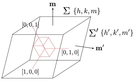
Figure 1.
The crystallographic and specimen frames.
We denote with an orthonormal frame, which is directed as the crystallographic directions , and and we assume that the orientation of in the crystallographic frame is given by . Accordingly, the unit normal to is given by:
We assume that we are able to measure the crystallographic orientation of another face , which is not parallel to and whose unit normal is
We define the orthonormal frame related to the specimen as
where is the orthogonal projector on . Clearly, there exists a rotation such that
and whose associated matrix in the frame is given by:
and whose components are uniquely determined once we find the orientation of the two planes and with respect to the crystallographic frame (For a different approach to the representation of the rotation matrix, see Appendix B).
2.2. Piezo-Optic Crystals
In a piezo-optic crystal, the inverse permittivity tensor depends on the Cauchy stress by the means of the linear Maxwell relation (also credited to Pockels, vid., e.g., [40]):
where is the inverse permittivity tensor of the unstressed crystal and is the fourth-order piezo-optic tensor; we recall that the eigenvalues of are related to the principal refraction indexes by:
We define the symmetry group of a piezo-optic crystal as
where denotes the orthogonal conjugator associated with , i.e.,
The tabular representation of the components and in the crystallographic frame for the crystallographic groups can be found, e.g., in [36,41]. Once we know the components in the frame , those in the specimen frame can be found by the means of (9)
then, the components of and in the frame are given by:
In the general case, the matrices of and in the frame shall be different from those in the frame : indeed, for a generic rotation whose orthogonal conjugator is , then
where with abuse of notation we used the tensor notation to represent the matrices in the two frames. Since, by (12):
then by (17) and (18), we obtain
and hence the conditions and imply:
Accordingly, in the most general case, the matrices of and in the frame shall have a structure different from those in the frame with a different number of non-null components and different relations between the components: however, provided we know the components of the generic rotation , by (16) the components in the specimen frame are uniquely determined from those in the crystallographic frame.
3. Stressed Cubic Crystals
In this section, we consider a stressed cubic crystal, whose inverse permittivity tensor is given by
where is the refraction index of the unstressed crystal. We assume that represents the residual stress due for instance to the growth cutting and polishing processes or to radiation induced defects, and also that is the plane stress:
whose representation in the frame is:
Accordingly, (21) admits the following representation in components in the specimen frame:
where the relevant components are given in terms of the components for the Cubic group and in terms of (9) into the Appendix A. The tensor is associated with the optical indicatrix (Figure 2) or index ellipsoid, which is defined as the locus:
whose property is that for any given direction of light propagation , the principal axes of the ellipsoid defined by:
are the refraction indexes associated with that direction of propagation. Now, if we assume that the specimen is observed along the direction of propagation , the equation of is:
whose principal axes are given by
where:
being
here we use Voigt’s notation as defined at the end of §.1.
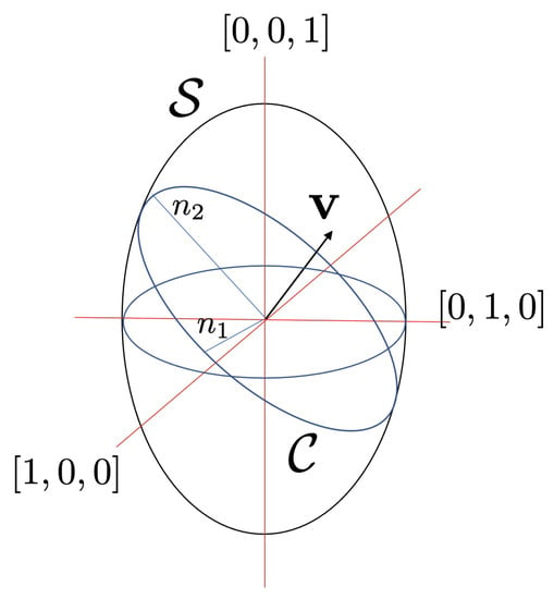
Figure 2.
The optical indicatrix.
As we did in [27,33,42], we assume that the stress is small, in the sense that:
with as a small parameter, in such a way that
By (29) and a trivial calculation, then within higher-order terms in we finally obtain
with
The principal directions of the ellipse are rotated with respect to the directions by an angle , which is given by:
We can detect the extinction directions, i.e., the directions where the polarizer and analyzer of the conoscopic system are aligned with the optic axes and which coincide with the eigenvectors, by following for instance the procedure explained in [26], vid. also [33]. In this case, the rotation of the polarizer of put the system in extinction mode, being the axis of the polarizer parallel to one of the principal axes of the section of the Optical Indicatrix and the analyzer, of course, normal to it. Moreover, by measuring the velocity of propagation of the light in the plane of , we can obtain a measure of the refraction indexes , even if the evaluation of the angle may be ambiguous.
Since we are able to measure , then by (33) and (35) we can obtain the set of parameters , which by (34) depends on the components of in the crystallographic frame, on the components of the rotation between such a frame and the specimen frame and on the three components of the plane stress:
then, provided and are given, from (34) we may obtain the values of the stress components as the solution of
It is important to remark that, in the case of residual stress, by photoelastic techniques, we obtain an average estimate of the stress components along the direction of observation.
Example
We consider a specimen of BaF (a typical optical component for optical thermometric instruments such as thermo-cameras and infrared pyrometers), that is cubic, class , and whose refraction index is at with piezo-optic components (in Pa):
The crystal is observed orthogonally to the plane and on this plane we measured , and rad. Another face of the specimen is parallel to the plane and accordingly, the face is rotated at an angle of around the direction
The component of in the specimen frame
are (in terms of ):
From (37), we then arrive at the following values for the plane stress components in the frame :
that are smaller than the BaF elastic limit which is MPa.
4. Conclusions
We considered a specimen of a cubic crystal whose faces are rotated with respect to the crystallographic planes, an instance that can occur when the crystals are cut from a boule with the aim to optimize the volume of finished crystals. We assumed that the crystal is observed by the means of a polariscope on one of its faces and that we are able, for instance by using XRD diffraction, to evaluate the Miller indexes of this face and of another one. The knowledge of the specimen surface with respect to the cubic crystallographic axes allows for the complete description of the rotation matrix, which connects the crystallographic and the specimen frame.
Provided this, and upon the assumption that the residual stress within the specimen is a plane stress in the observed face, we are able to express the relation between the refraction index in the observation plane and the three components of the residual stress in terms of the components of the piezo-optic tensor and the rotation matrix. The equation we obtained allows for a complete identification of the residual plane stress once we are able to experimentally measure the refraction index and the extinction direction in the observation plane. We finish by proposing an example for the numerical validation of the model with the data for a BaF crystal.
The proposed model will allow for the development of methods and systems for quality assessment and monitoring of optical components, which are critical in many optical and electro-optical apparatuses and whose application fields span medicine, telecommunications, aerospace engineering, high-energy physics, and environmental control.
Author Contributions
Conceptualization, methodology F.D., D.R. and L.M.; writing—original draft preparation, F.D.; writing—review and editing, D.R. and L.M. All authors have read and agreed to the published version of the manuscript.
Funding
This research was partially funded by the Italian Ministero dell’Istruzione, dell’Universitá e della Ricerca (MIUR), PRIN project “SHERPA” 2020EZ8EPB.
Institutional Review Board Statement
Not applicable.
Informed Consent Statement
Not applicable.
Data Availability Statement
No new data were created.
Acknowledgments
The research leading to these results is within the scope of CERN R&D Experiment 18 “Crystal Clear Collaboration” and the PANDA Collaboration at GSI-Darmstadt. This work was done under the auspices of the Italian Gruppo Nazionale per la Fisica Matematica (GNFM) and Istituto Nazionale di Alta Matematica (INDAM). We wish to thanks the reviewer for their well-accepted and useful comments.
Conflicts of Interest
The authors declare no conflict of interest.
Abbreviations
The following abbreviations are used in this manuscript:
| DICEA | Dipartimento di Ingegneria Civile, Edile ed Architettura, |
| Universitá Politecnica delle Marche, 60131 Ancona, Italy | |
| SIMAU | Dipartimento di Scienze e Ingegneria dei Materiali e Urbanistica |
| Universitá Politecnica delle Marche, 60131 Ancona, Italy | |
| ICRYS | Interdipartimental Research Center for Global Analysis of Crystals |
| Universitá Politecnica delle Marche, 60131 Ancona, Italy | |
| INFN | Istituto Nazionale di Fisica Nucleare |
| PANDA | Anti-Proton ANnhilation at Darmstadt Experiment |
| XRD | X-ray diffraction. |
Appendix A
For the cubic group, the piezo-optic matrix has tabular representation in the frame for the two classes 23 and (vid., e.g., [36,41]):
whereas that for the classes 432, and can be obtained by putting
into (A1).
Appendix B
A rotation can be represented, once the pair angle of rotation and axis of rotation is given, by means of the Rodrigues formula [43]:
where the and are, respectively, given by
in an orthonormal frame , the associated matrix has the simple representation:
In Section 2, we represented the rotation matrix in terms of the two vectors and and one may wonder how to recover the pair from (uid12). To obtain the rotation angle, we simply consider the trace of , which is one of the orthogonal invariants:
as far as the axis is concerned, since by definition the axis is the eigenvector with a unit eigenvalue, i.e., , then its components can be obtained by solving the system:
provided . We obtain:
with
Conversely, the components of are given in terms of the components of by:
References
- Dall, J.W.; Riley, W.F. Experimental Stress Analysis; Mc Graw-Hill: New York, NY, USA, 1987. [Google Scholar]
- Aben, H.; Guillemet, C. Photoelasticity of Glass; Springer: Berlin/Heidelberg, Germany, 1993. [Google Scholar]
- Frocht, M.M. Photoelasticity: The Selected Scientific Papers of M.M. Frocht; Pergamon Press: Oxford, UK, 1969. [Google Scholar]
- Ajovalasi, A.; Petrucci, G.; Scafidi, M. Review of RGB photoelasticity. Opt. Lasers Eng. 2015, 68, 58–73. [Google Scholar] [CrossRef]
- Ramesh, K. Digital Photoelasticity: Advanced Techniques and Applications; Springer: Berlin/Heidelberg, Germany, 2000. [Google Scholar]
- Rastogi, P.K. Photomechanics; Springer: Berlin/Heidelberg, Germany, 2000. [Google Scholar]
- Montalto, L.; Natali, P.P.; Scalise, L.; Paone, N.; Daví, F.; Rinaldi, D.; Barucca, G.; Mengucci, P. Quality Control and Structural Assessment of Anisotropic Scintillating Crystals. Crystals 2019, 9, 376. [Google Scholar] [CrossRef]
- Korzhik, M.; Gektin, A. Engineering of Scintillation Materials and Radiation Technologies. In Proceedings of the ISMART 2016, Springer Proceedings in Physics, Minsk, Belarus, 26–30 September 2016; Springer: Cham, Switzerland, 2018. [Google Scholar]
- Maddalena, F.; Tjahjana, L.; Xie, A.; Arramel; Zeng, S.; Wang, H.; Coquet, P.; Drozdowski, W.; Dujardin, C.; Dang, C.; et al. Inorganic, Organic, and Perovskite Halides with Nanotechnology for High-Light Yield X- and γ-ray Scintillators. Crystals 2019, 9, 88. [Google Scholar] [CrossRef]
- Fabjan, C.W.; Gianotti, F. Calorimetry for particle physics. Rev. Mod. Phys. 2003, 75, 1243. [Google Scholar] [CrossRef]
- Zhu, R.-Y. Precision crystal calorimeters in high-energy physics: Past, present, and future. In Proceedings of the Optical Engineering + Applications, San Diego, CA, USA, 10–14 August 2008; Available online: https://www.spiedigitallibrary.org/conference-proceedings-of-spie/7079.toc?SSO=1 (accessed on 4 March 2023).
- Bornheim, A.; Apresya, A.; Duarte, J.; Pena, C.; Ronzhin, A.; Spiropulu, M.; Xie, S. Calorimeters for Precision Timing Measurements in High Energy Physics. In Proceedings of the 16th International Conference on Calorimetry in High Energy Physics (CALOR 2014) IOP Publishing. J. Phys. Conf. Ser. 2015, 587, 012057. [Google Scholar] [CrossRef]
- Donghia, R. The Mu2e experiment at Fermilab: Design and status. Il Nuovo Cim. 2017, 40, 176. [Google Scholar]
- The PANDA Collaboration; Barucca, G.; Davı, F.; Lancioni, G.; Mengucci, P.; Montalto, L.; Natali, P.P.; Paone, N.; Rinaldi, D.; Scalise, L.; et al. Precision resonance energy scans with the PANDA experiment at FAIR: Sensitivity study for width and line-shape measurements of the X(3872). Eur. Phys. J. A 2019, 55, 42. [Google Scholar] [CrossRef]
- Golutvin, A. Review of calorimeters. Nucl. Instrum. Methods Phys. Res. A 2000, 453, 192–198. [Google Scholar] [CrossRef]
- Lecoq, P. Development of new scintillators for medical applications. Nucl. Instrum. Methods Phys. Res. A 2016, 809, 130. [Google Scholar] [CrossRef]
- Lecoq, P.; Annekov, A.; Getkin, A.; Korzhik, M.; Pedrini, C. Inorganic Scintillators for Detector Systems; Springer: Berlin/Heidelberg, Germany; New York, NY, USA, 2006. [Google Scholar]
- Akkerman, Q.A.; Manna, L. What Defines a Halide Perovskite? ACS Energy Lett. 2020, 5, 604–610. [Google Scholar] [CrossRef]
- Dhanaraj, G.; Byrappa, K.; Prasad, V.; Dudley, M. (Eds.) Springer Handbook of Crystal Growth; Springer: Berlin/Heidelberg, Germany, 2010. [Google Scholar]
- Montalto, L.; Paone, N.; Scalise, L.; Rinaldi, D. A photoelastic measurement system for residual stress analysis in scintillating crystals by conoscopic imaging. Rev. Sci. Instrum. 2015, 86, 063102. [Google Scholar] [CrossRef] [PubMed]
- Montalto, L.; Paone, N.; Rinaldi, D.; Scalise, L. Inspection of birefringent media by photoelasticity: From diffuse light polariscope to laser conoscopic technique. Opt. Eng. 2015, 54, 081210. [Google Scholar] [CrossRef]
- Natali, P.P.; Montalto, L.; Daví, F.; Paone, N.; Rinaldi, D.; Scalise, L. Optimization of the photoelastic fringe pattern processing for the stress evaluation in scintillating anisotropic media. In Proceedings of the IEEE International Instrumentation and Measurement Technology Conference (I2MTC), Torino, Italy, 22–25 May 2017. [Google Scholar]
- Natali, P.P.; Montalto, L.; Rinaldi, D.; Daví, F.; Paone, N.; Scalise, L. Non invasive Inspection of Anisotropic Crystals: Innovative Photoelasticity-Based Methods. IEEE Trans. Nucl. Sci. 2018, 65, 2203–2207. [Google Scholar] [CrossRef]
- Montalto, L.; Rinaldi, D.; Scalise, L.; Paone, N.; Daví, F. Photoelastic sphenoscopic analysis of crystals. Rev. Sci. Instrum. 2016, 87, 015113. [Google Scholar] [CrossRef] [PubMed]
- Daví, F. On the Bertin Surfaces for Photoelastic Crystals. J. Opt. Soc. Am. A 2015, 32, 2323–2337. [Google Scholar] [CrossRef] [PubMed]
- Wahlstrom, E.E. Optical Crystallography; Wiley: New York, NY, USA, 1960. [Google Scholar]
- Rinaldi, D.; Daví, F.; Montalto, L. On the photoelastic constants and the Brewster law for stressed tetragonal crystals. Math. Methods Appl. Sci. 2018, 41, 3103–3116. [Google Scholar] [CrossRef]
- Daví, F.; Rinaldi, D.; Montalto, L. On the photoelastic constants for stressed anisotropic crystals. Nucl. Inst. Methods Phys. Res. A 2019, 947, 162782. [Google Scholar]
- Rinaldi, D.; Montalto, L.; Natali, P.P.; Daví, F. Elasto-optic properties and internal stress analysis for monoclinic and trigonal crystals. J. Instrum. 2021, 16, P08018. [Google Scholar] [CrossRef]
- Stadnyk, V.Y.; Matviiv, R.B.; Shchepanskyi, P.A.; Rudysh, M.Y.; Kogut, Z.A. Photoelastic Properties of Potassium Sulfate Crystals. Phys. Solid State 2019, 61, 2130–2133. [Google Scholar] [CrossRef]
- Mytsyk, B.; Stadnyk, V.; Demyanyshyn, N.; Kost, Y.; Shchepanskyi, P. Photoelasticity of ammonium sulfate crystals. Opt. Mater. 2019, 88, 723–728. [Google Scholar] [CrossRef]
- Mytsyk, B.; Andrushchak, A.; Vynnyk, D.; Demyanyshyn, N.; Kost, Y.; Kityk, A. Characterization of photoelastic materials by combined Mach-Zehnder and conoscopic interferometry: Application to tetragonal lithium tetraborate crystals. Opt. Lasers Eng. 2020, 127, 105991. [Google Scholar] [CrossRef]
- Rinaldi, D.; Natali, P.P.; Montalto, L.; Daví, F. The Refraction Indices and Brewster Law in Stressed Isotropic Materials and Cubic Crystals. Crystals 2021, 11, 1104. [Google Scholar] [CrossRef]
- Sirotin, Y.I.; Shaskolskaya, M.P. Fundamentals of Crystal Physics; Mir: Moscow, Russia, 1982. [Google Scholar]
- Perelomova, M.V.; Tagieva, M.M. Problems in Crystal Physics with Solutions; MIR Publishers: Moscow, Russia, 1983. [Google Scholar]
- Nye, J.F. Physical Properties of Crystals: Their Representation by Tensors and Matrices; Oxford University Press: Oxford, UK, 1985. [Google Scholar]
- Balzar, D.; Von Dreele, R.B.; Bennet, K.; Ledbetter, H. Elastic-strain tensor by Rietveld refinement of diffraction measurements. J. Appl. Phys. 1998, 84, 4822–4833. [Google Scholar] [CrossRef]
- Popa, N.C.; Balzar, D. Elastic strain and stress determination by Rietveld refinement: Generalized treatment for textured polycrystals for all Laue classes. J. Appl. Crystallogr. 2001, 34, 187–195. [Google Scholar] [CrossRef]
- Korsunsky, A.M.; Salvati, E.; Lunt, A.G.J.; Sui, T.; Mughal, M.Z.; Daniel, R.; Keckes, J.; Bemporad, E.; Sebastiani, M. Nanoscale residual stress depth profiling by Focused Ion Beam milling and eigenstrain analysis. Mater. Des. 2018, 145, 55–64. [Google Scholar] [CrossRef]
- Narasimhamurty, T.S. Photoelastic and Electro-Optic Properties of Crystals; Plenum Press: New York, NY, USA, 1981. [Google Scholar]
- Authier, A. (Ed.) International Tables for Crystallography. Volume D: Physical Properties of Crystals; Kluwer Academic Publishers: Dordrecht, The Netherlnads, 2003. [Google Scholar]
- Daví, F.; Rinaldi, D. Mechanical and optical properties of anisotropic single-crystal prisms. J. Elast. 2015, 120, 197–224. [Google Scholar] [CrossRef]
- Rodrigues, O. Des lois géométriques qui régissent les déplacements d’un système solide dans l’espace, et de la variation des coordonnées provenant de ces déplacements considérés indépendants des causes qui peuvent les produire. J. Math. Pures Appl. 1840, 5, 380–440. [Google Scholar]


Disclaimer/Publisher’s Note: The statements, opinions and data contained in all publications are solely those of the individual author(s) and contributor(s) and not of MDPI and/or the editor(s). MDPI and/or the editor(s) disclaim responsibility for any injury to people or property resulting from any ideas, methods, instructions or products referred to in the content. |
© 2023 by the authors. Licensee MDPI, Basel, Switzerland. This article is an open access article distributed under the terms and conditions of the Creative Commons Attribution (CC BY) license (https://creativecommons.org/licenses/by/4.0/).