Abstract
The cutting process generates specific mechanical characteristics in the subsurface layers of the shaped parts. These characteristics have a decisive influence on the working properties and product durability of these parts. The orthogonal cutting process of structural heat-treated steel’s effect on the mechanical properties of the machined subsurface layers was evaluated by instrumented the nanoindentation method and sclerometry (scratch) method. As a result of this study, the relationship between the specific work in the tertiary cutting zone and the total deformation work during indenter penetration during the instrumented nanoindentation was established. The dependence of the indenter penetration depth during sclerometry of the machined subsurface layers of the workpiece was also studied. The orthogonal cutting process was carried out at different cutting speeds and tool rake angles. The cutting speed increase and the increase in the tool rake angle cause an increase in the indenter penetration work during the instrumented nanoindentation and an increase in the maximum indenter penetration depth during sclerometry. Simultaneously, the measured microhardness of the machined surfaces decreases with both an increase in cutting speed and an increase in the tool rake angle.
1. Introduction
The main objectives of the cutting process used in shaping and finishing operations are to ensure the required geometric shape and dimensional accuracy of the part, as well as the specified quality of the machined surfaces. By performing this objective, the cutting process realizes the tool penetration into the machined material. In this case, the machined subsurface layers of the workpiece are affected by thermomechanical loads as a result of this penetration. The consequences of these loads are plastic strain and subsequent damage of the machined layers with the formation of chips. These processes contribute significant changes in the machined subsurface layers of the workpiece. As a result, specific mechanical characteristics are generated in them. These characteristics have a fundamental effect on the working properties and longevity of the part being shaped in the cutting process. To evaluate such mechanical characteristics, the hardness characteristics of the machined subsurface layers [1] and the total residual stresses formed in them [2] are usually used. The methods used to measure these characteristics have been well established for quite a long time, providing an evaluation of the subsurface state of the parts. However, these methods ensure just a macro estimate of the mechanical characteristics of the machined surfaces. They are insufficiently sensitive to the conditions of thermomechanical effects from the cutting process on the machined surfaces of the workpiece. High sensitivity in evaluating the mechanical characteristics of the subsurface layers of shaped parts using different machining processes is ensured by micro- and nanometric control methods: instrumented nanoindentation and sclerometry (scratch test).
The presented paper is devoted to the evaluation of integral mechanical characteristics in the workpiece subsurface layers generated as a result of the cutting process, and the study of the relationship between these characteristics and the factors influencing them from the orthogonal cutting process.
2. Methods for the Determination of Machined Layers Mechanical Properties
In the past few decades, micro- and nanometric methods have been used to evaluate the mechanical characteristics of materials and parts. These methods include instrumented nanoindentation [3,4] and sclerometry (scratching or scratch test) [5]. The techniques [6] used in the application of these evaluation methods provide extended possibilities for determining the mechanical characteristics of the material’s subsurface layers both in instrumented nanoindentation [7] and in sclerometry [8]. The prototype of instrumental nanoindentation as a process of continuous penetration of an indenter into a test material, which undergoes elastic loading, plastic strain, and subsequent damage, may be the study of Atkins and Tabor [9]. The method of material testing by continuously indenter loading and then unloading was further refined by developing methods and devices to measure the indenter load while simultaneously measuring the depth of its penetration into the tested material [10]. At the same time, the indenter penetration depth was narrowed to the nano-scale range. The result of this research was the creation of a widely used instrumented nanoindentation method. Nanoindentation is a well-established method for studying the mechanical properties of various materials. This method is widely represented in well-known publications: see, for example, [11].
Methods for analyzing the indenter penetration diagram were originally presented in the studies of Doerner and Nix [12] as well as Oliver and Pharr [13]. In particular, they presented methods for estimating hardness and Young’s modulus based on the initial slope of the unloading curve. The different results of determining the hardness value obtained using the nanoindentation method were analyzed in a study by Vargas and colleagues [14]. Kang et al. studied various optimization methods to determine the material mechanical properties through instrumented nanoindentation [15]. Guillonneau and colleagues proposed a method for determining the mechanical properties based on the analysis of contact stiffness fluctuations in the tested materials [16]. The friction effect in the contact between the indenter and the studied material was investigated by Harsono and colleagues [17]. The relationship between indentation modes and mechanical properties of materials, taking into account friction and the inclination angle value of the indenter’s working part is presented in Wang’s study [18]. Sivaram and colleagues studied the effects of the pile-up and sink-in effect on the material’s mechanical properties during instrumental nanoindentation of thin coatings and integrated circuit materials [19].
When evaluating the mechanical properties of the studied materials and coatings, the researchers mostly concentrate on determining the microhardness of the subsurface layers (see, e.g., [20]) and the residual stresses formed in them (see, e.g., [21]). This is especially the case when evaluating the mechanical properties of various steels and alloys. Furthermore, plasma hardened wheel steels [22], additively manufactured stainless steels [23], as well as steels used to manufacture gear wheels [24] and many others have been investigated. Moon and colleagues studied the contribution of the steel microstructure components to its hardening [25]. The estimation of dislocation density by measuring the microhardness of heterogeneous materials was studied in the work of Mendas et al. [26] and Ameri and colleagues [27]. The application of the instrumented nanoindentation method to evaluate the residual stresses (see, e.g., [21,28,29]) provided the possibility to obtain important information about the mechanical properties of the subsurface layers of the tested materials and coatings. This is particularly important for the characterization of surfaces processed by various mechanical processes, in particular by cutting, plastic deformation, heat treatment, etc., and the tool working surfaces used to realize such processes. Moreover, the method of instrumented nanoindentation is also used to study and evaluate the stress–strain state of the workpiece’s subsurface layers. Using nanoindentation, the strain degree of additively manufactured stainless steels [30], Fe-ion-irradiated steels [31], structural steels under tensile loads [32], the strain degree, fracture process, and microstructure changes of austenitic steels [33,34] and others have been evaluated. Wagner et al. studied the behavior of non-metallic particles in 42CrMo4 alloyed steel [35]. Zhou and colleagues studied the effect of indenter loading modes and conditions during nanoindentation of hardened alloy steel [36].
Instrumented nanoindentation has been further advanced due to the recent rapid development of numerical modeling for this method. A nanoindentation three-dimensional model of tool steel coatings is presented in a study by Bobzin et al. [37]. Khan and his colleagues developed a finite-element model of the nanoindentation process of corrosion-resistant aluminum coating [38]. The material model parameters were also determined using inverse fitting via experimental macromechanical testing of the coating material. The same inverse method of determining the parameters of the thin-film metallic glass material model was applied by Han et al. [39]. In this case, the determination of material model parameters is additionally supported using an artificial neural network. The evaluation of the mechanical properties of thin metal coatings using indentation simulation is devoted to the work of Wittler et al. [40]. The Pöhl study presents a method for determining the basic mechanical properties of the test material [41]. Recommendations are provided on the possibilities of determining these properties from the simulated process of indenter penetration into the studied material.
An important part of the instrumental nanoindentation method studies is the investigations devoted to the improvement of instruments and devices for this method implementation. The accuracy and repeatability of results obtained with nanoindentation are ensured by various methods of these devices’ calibration: see, e.g., [30]. Peng and colleagues developed a handheld device to implement the nanoindentation method [42]. The indentation force applied to the indenter is detected by a voice coil motor, and the indenter movement is detected using an eddy current transducer. Li and colleagues developed a method for instrumental nanoindentation device calibration [43] based on the use of an optical sonde interferometer and a step height reference. The effect of environmental temperature on the results of nanoindentation tests directly during these tests was studied by Fritz and Kiener [44].
The scratch test (sclerometry) was developed almost in parallel with the instrumented nanoindentation method [45]. The scratch test is well suited for the qualitative characterization of thin, hard coatings applied by different methods [46,47]. This test has been widely used for many years in studies of coating–substrate contact adhesion [48,49]. The scratch test is characterized by its relative simplicity and cost-effectiveness, as well as by the fact that no thorough preparation of the test specimen surface is necessary [46]. At the same time, the scratch test is subject to some uncertainty, especially when determining the fracture load of the examined surface [50]. To reduce the uncertainty in determining the mechanical characteristics of the tested subsurface layers of materials using the scratch test, the multi-pass test has been used in recent decades [51,52]. The multi-pass scratch test is characterized by multiple scratches on the same trace with the progressive or constant load on the indenter. The resulting subsurface fractures are determined either by evaluating the scratch images [51] or by analyzing the characteristics of the scratch test: the tangential load on the indenter or the indenter penetration depth [52]. In the last few decades, the scratch test has also been used to study the mechanical properties of subsurface layers from materials, mainly metals processed using cutting or plastic deformation, and to study the tribomechanical characteristics of contacting surfaces during application [53]. Aurich and Steffes studied the mechanical properties of the subsurface layers during grinding using single-grain scratching [54]. The effect of cutting speed on the plastic strain degree of AISI 4140H steel and the formation of pile-up was established. Fan and colleagues studied the plastic mechanisms of dislocations during the scratch test [55]. The effect of scratching modes with a single grain of titanium alloy Ti-6Al-4V on the indenter penetration depth and pile-up height was studied by Pratap et al. [56]. Thus, the scratch test can be successfully applied to evaluate the effect of material machining processes on the mechanical characteristics of the subsurface layers subjected to a thermo-mechanical impact during processing.
The instrumented nanoindentation method and the scratch test (sclerometry) ensure the measurement not only of individual mechanical characteristics of the tested specimens, such as microhardness, indenter penetration depth, residual stress values, etc., but also of the integral mechanical characteristics of the subsurface layers, in particular the indenter penetration work (energy), its elastic and plastic parts. In this regard, the mechanical state of the subsurface layers subjected to thermomechanical impact through various machining processes is of special interest [57]. The effect of machining conditions on the strain energy of the subsurface layers is presented in a study by Bezyazychny and colleagues [58]. Yamamoto et al. studied the relationship between the elastic and plastic components, as well as the total energy of the indentation, and the microhardness of the tested metals [59]. Ren and Liu [60] and Wang with colleagues [61] devoted their research to studying the relationship between the mechanical properties of hard-working metals and alloys and the cutting process conditions.
The analysis of instrumental nanoindentation and sclerometry methods has shown the essential possibilities of these techniques for micro- and nanometric analysis in determining the mechanical characteristics generated in the shaping process of the subsurface layers of various parts. Thus, these methods can be successfully used to evaluate the influence of generalized cutting process parameters on the formed integral mechanical characteristics of the subsurface layers.
3. Materials and Methods
The cutting process has a significant impact on the machined surface of the shaped part. In addition to ensuring a predetermined geometric shape of the part and microgeometry of the machined surface, the cutting process also generates the physical and mechanical characteristics of the workpiece’s subsurface layers. The cutting process’s effect on these subsurface layer properties of the machined workpiece is multifaceted and often confrontational. A significant role in this influence is played by the multiplicity and complexity of physical and mechanical processes occurring in the cutting zones of real spatial machining processes such as drilling, milling, threading, etc. To neutralize the secondary effects influence of deformation and subsequent damage of the machined material that takes place in real three-dimensional machining processes, the influence of the cutting process on the formation of physical and mechanical characteristics of the machined surfaces was studied in the conditions of a two-dimensional (free orthogonal) cutting process.
3.1. Materials
Experimental studies of the formation of the physical and mechanical characteristics of the subsurface layers through the machining process were performed on a special stand, reproducing the orthogonal cutting process [62,63]. The experimental stand ensures rectilinear movement of the table with the workpiece relative to the fixed tool with a stepless adjustable cutting speed from 0 to 200 m/min [64]. A well-known representative of heat-treated structural steel AISI 1045 was selected as the machined material. The chemical composition of AISI 1045 steel is specified in Table 1. The mechanical and thermal properties of the steel AISI 1045 are listed in Table 2.
The workpieces of the machined material were pre-grinded to ensure the necessary accuracy, in particular the side parallelism. The final workpiece size was 170 mm × 60 mm × 3 mm. The workpieces were then subjected to annealing to ensure a uniform material structure and the absence of residual stresses. The workpiece hardness after annealing was 180 HB. SNMG-SM-1105 (ISO SNMG 15 06 12-SM 1105) replacement carbide inserts, Sandvik Coromant, Sandviken, Sweden, were used as cutting elements. Table 2 shows the mechanical and thermal properties of this carbide cutting insert. The cutting wedge geometry required for a stable cutting process was ensured by installing a replaceable carbide plate in the tool body at a pre-defined inclination angle and grinding the tool clearance face [64]. The tool clearance angle was α = 8° and the curvature radius of the cutting edge was ρ = 20 µm. Grinding wheels and grinding pastes [65,66] made of synthetic superhard materials were used for grinding and subsequent polishing of carbide inserts. The cutting forces for subsequent determination of the cutting power were measured on the workpiece [62,64]. For this, the workpiece was clamped in a three-component Kistler type 9121 dynamometer using a special clamping device—Figure 1a. Experimental studies were performed at different cutting speeds and different tool rake angles.
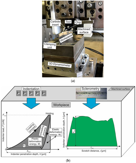
Figure 1.
Experimental setup for the realization of the orthogonal cutting process and scheme for determination of an instrumented nanoindentation and sclerometry of machined surfaces: (a) experimental setup for cutting forces measurement; (b) instrumented indentation and sclerometry diagrams.

Table 1.
Chemical composition of the steel AISI 1045 [67].
Table 1.
Chemical composition of the steel AISI 1045 [67].
| Material | Fe | C | Si | Mn | P | S | Cr |
|---|---|---|---|---|---|---|---|
| AISI 1045 | 98.51–98.98% | 0.420–0.50% | ≤0.04% | 0.50–0.90% | ≤0.03% | ≤0.035% | ≤0.4% |
Table 2.
Mechanical and thermal properties of the steel AISI 1045 steel and carbide insert [67,68].
Table 2.
Mechanical and thermal properties of the steel AISI 1045 steel and carbide insert [67,68].
| Material | Strength (MPa) | Elastic Modulus (GPa) | Elongation (%) | Hard-ness | Poisson’s Ratio | Specific Heat (J/kg·K) | Thermal Expansion (µm/m·°C) | Thermal Conductivity (W/m·K) | |
|---|---|---|---|---|---|---|---|---|---|
| Tensile | Yield | ||||||||
| AISI 1045 | 690 | 620 | 206 | 12 | HB 180 | 0.29 | 486 | 14 | 49.8 |
| SNMG-SM-1105 | - | - | 650 | - | HRC 76 | 0.25 | 251 | - | 59 |
The cutting speed VC was set at four levels: 48 m/min (0.8 m/s), 96 m/min (1.6 m/s), 144 m/min (2.4 m/s), and 192 m/min (3.2 m/s). The tool rake angle had the following values: −10°, 0°, and 10°. To determine the cutting forces on the tool clearance face, the depth of cut (undeformed chip thickness) was varied in three levels and was 0.1 mm, 0.2 mm, and 0.3 mm. The cutting process was repeated for each value of cutting speed and tool rake angle at least 5 times. The measuring results of cutting forces were averaged over these repetitions. The maximum uncertainty in measuring the cutting forces was not more than 10%.
The influence of the cutting process on the mechanical characteristics of the machined workpieces’ subsurface layers was evaluated by instrumented nanoindentation and sclerometry of the machined surfaces—Figure 1b. To perform the above analysis, thin sections of the workpiece part with a machined surface were prepared [69]. Micromechanical studies of the mechanical characteristics of the machined subsurface layers were carried out on the “Micron-gamma” device [52,70]. The indenter is loaded via an electromagnetic loader. The indenter penetration depth is determined by a differentially switched inductive sensor [70]. This ensures minimal temperature drift. The accuracy of the indenter depth measurement is 5 nm. Instrumented nanoindentation of the machined surfaces was performed at a maximum indenter load of 350 mN. The accuracy of the indenter load setting is 0.02 mN. The change rate of the indenter load was 30 mN/s. After reaching the maximum load on the indenter, the nanoindentation process was delayed at this load and then unloading was performed. The delay time was 5 s.
To perform instrumental nanoindentation and sclerometry, a Berkovich indenter was used. The total penetration energy W as well as its plastic Wpl and elastic We parts were determined from the instrumented nanoindentation diagram—Figure 1b. The instrumented nanoindentation process was repeated at least 12 times for each set value of cutting speed and tool rake angle. The result of determining the indenter penetrating energy was averaged over the tests performed. The measurement uncertainty was no more than 9%. Sclerometry of machined workpiece surfaces was performed at an indenter load of 100 mN. The indenter movement speed was 20 µm/s. The scratch length was about 630 µm. The maximum indentation depth along the scratch length was determined from the sclerometry diagram—Figure 1b.
The sclerometry process of machined workpiece surfaces was repeated at least 10 times for each value of cutting speed and tool rake angle. The measurement results were then averaged. The uncertainty in determining the maximum indenter penetration depth along the length of the scratch was no more than 12%. An optical profilometer “Micron-alpha” was used to analyze the scratches applied on the “Micron-gamma” device [52]. The scanning principle of the profilometer is based on white light interferometry. This provides a non-contact study of machined surface microtopography with a vertical resolution of 2 nm.
3.2. Methods
As a result of the elastic–plastic interaction of the tool with the machined material and subsequent damage of this material through chip formation, along with the geometric characteristics of the machined subsurface layers, certain physical and mechanical characteristics are also formed in the cutting process. The value and parameters of these characteristics’ distribution with constant materials of the contact pair (the pairing tool—machined material) are substantially determined by the conditions of the cutting process: cutting conditions, tool geometry, the presence or absence of lubrication and cooling, etc. Depending on these conditions, different mechanical properties of the subsurface layers are generated, generally characterized by their hardening or softening [62,71,72]. Whether the conditions of adiabatic hardening or isothermal softening prevail in the cutting zones depends on whether the hardened or softened layer of the machined material is formed [73,74]. This process is determined by the contact conditions between the tool and the machined material in the primary and tertiary cutting zones [74], wherein the contact conditions in the tertiary cutting zone have an overwhelming influence [62]. Therefore, the influence of the contact conditions of the tool with the workpiece in this cutting zone is considered further. This influence is evaluated by the energy impact of the tool on the machined material, forming a certain stress–strain state in this material. The formed stress–strain state generates, in turn, certain physical and mechanical characteristics of the subsurface layers. These characteristics remain after the cutting process is finished and the thermomechanical loads are removed. In the cutting process, the contact of the tool clearance face with the workpiece surface is characterized by two stresses: qsz—stress in the contact of the stagnation zone with the workpiece at length hsz and qfw—stress in the contact of the tool clearance face chamfer with the workpiece at length hfw—Figure 2.
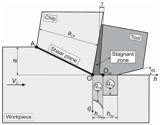
Figure 2.
Scheme for the interaction of the tool with the workpiece in the tool clearance face.
The energy interaction of the tool clearance face with the workpiece surface that results in the stresses qsz and qfw can be determined by three different methods:
- according to the cutting work in the tertiary zone, similar to the determination of the specific deformation work in the primary cutting zone [71,72,73,74];
- according to the stresses acting on the tool clearance face during the cutting process [71,73,75];
- according to the cutting power on the tool clearance face [71,75].
In this study, the energy interaction was estimated using the third method, as the product of the cutting forces acting on the tool clearance face and the relative speed between the tool and the workpiece:
where Pccf is the cutting power on the tool clearance face, Ptcf is the thrust power on the tool clearance face, Fccf is the cutting force on the tool clearance face, Ftcf is the thrust force on the tool clearance face, and VC is the cutting speed.
The cutting forces acting during machining on the tool clearance face (in the tertiary cutting zone) were determined using the value of total cutting forces at the undeformed chip thickness (depth of cut for orthogonal cutting), equal to zero [71,75]. To determine these forces, the dependences of the total cutting forces on the depth of cut were extrapolated to a cutting depth equal to zero [62,76]:
where is the existence space of kinetic characteristics in the cutting process, k is the dimensionality of the existence space, a is the depth of cut (unformed chip thickness), FC is the total cutting force, and FT is the total thrust force.
The mechanical characteristics of the workpiece subsurface layers generated as a result of the cutting process are evaluated in this study based on the indenter penetration work as a result of the instrumented nanoindentation and the maximum indenter penetration depth during sclerometry (see Section 3.1). Since these characteristics are generated as a result of the interaction of the tool clearance face with the workpiece surface (see above), the correspondence of the indenter penetration work and its maximum penetration depth with the cutting power at the tool clearance face is considered. This is postulated by the following statement:
- ➢
- Thermomechanical interaction of the tool with the workpiece (mainly in the tertiary cutting zone) is evaluated based on the cutting power at the tool clearance face in proportion to the indenter penetration work in the machined surface of the workpiece, estimated using instrumented nanoindentation and in proportion to the maximum indenter penetration depth in the subsurface layers, and estimated using sclerometry of the machined subsurface layers:
4. Results
The thermomechanical impact of the tool on the machined workpiece during cutting is accompanied by significant plastic deformation of the machined material and its subsequent failure with chip formation. This impact generates in the machined subsurface layers of the workpiece’s specific mechanical characteristics and the corresponding material microstructure. In this case, in different cutting zones, different mechanical characteristics and different microstructures of the machined material corresponding to its stress–strain state in each cutting zone are observed. Based on the generated mechanical characteristics of the subsurface layers and the formed microstructure of the machined material, the degree of the material thermomechanical loading in each cutting zone can be estimated [71,72,73]. This loading degree is ensured through specific conditions (characteristics) of the cutting process, acting mainly in the tertiary cutting zone (see Section 3.2).
4.1. Cutting Process Characteristic
Figure 3 shows a scheme of the free orthogonal cutting process and the microstructure of the machined material in different cutting zones.
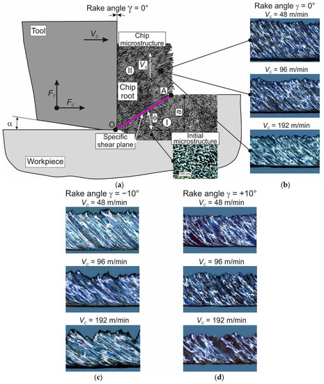
Figure 3.
Orthogonal cutting scheme with chip microstructure images at different cutting speeds and tool rake angles: (a) orthogonal cutting scheme, combined with the chip root and an image of the initial microstructure; (b) chip microstructure images at a tool rake angle γ = 0° and different cutting speeds; (c) chip microstructure images at a tool rake angle γ = −10° and different cutting speeds; (d) chip microstructure images at a tool rake angle γ = +10° and different cutting speeds. (The following symbols are used in the figure: VS—chip speed; φ—shear angle; FC and FT—cutting and thrust force, respectively).
Cutting process scheme aligned with the chip root—Figure 3a. In the primary cutting zone I, characterized by insignificant plastic strain and low cutting temperatures, the initial microstructure of the machined material is preserved almost up to the specific shear plane (see Figure 3a). The initial microstructure of the machined material (AISI 1045 steel) corresponds to the microstructure of structural heat-treated steels after annealing, which has been widely reported in publications [67,71,72]. The microstructure of workpieces subjected to the subsequent cutting process had a ferrite–perlite structure. The image of the initial microstructure shows light ferrite grains and dark pearlite grains (see Figure 3a). In the secondary cutting zone II, after passing the specific shear plane, the machined material is subjected to significant plastic deformation and significant cutting temperature. This cutting zone is characterized by a significant gradient in the strain degree and cutting temperature [62,71,73]. As a result, the material microstructure (formed chips) in the secondary cutting zone is textured [77]. Images of the chip microstructure at different cutting speeds for the tool rake angle γ = 0°, shown in the cutting process scheme (see Figure 3a), are presented in Figure 3b. The chip microstructure images for the tool rake angles γ = −10° and +10° at the different studied cutting speeds are shown in Figure 3c,d, respectively.
With increasing the cutting speed VC, the inclination of the chip deformation texture increases for all studied tool rake angles (see Figure 3b–d). This is explained by the fact that with increasing the cutting speed VC, the movement speed of the chip material layers VS increases proportionally. At the same time, increasing the tool rake angle causes a decrease in the inclination angle of the chip deformation texture. In all likelihood, this is due to the significantly greater strain degree of the machined material at negative tool rake angles (see Figure 3c). Decreasing the tool rake angle also increases shear strain in the chips of the machined material. With a significant value of cutting speed VC and negative tool rake angles, the shear strain of the chip material increases significantly. This results in the formation of a shear band (see Figure 3c, VC = 192 m/min). As a result of this stress–strain state of the machined material in the secondary cutting zone, there is a transformation from the formation of flow chips to the formation of segmented chips [77].
To determine the cutting power during the interaction of the tool clearance face with the workpiece machined surface (tertiary cutting zone), the cutting forces on the tool clearance face are identified when the cutting speed and the tool rake angle are changed. These forces are determined by extrapolating the dependence of cutting forces on the depth of cut (undeformed chip thickness) to zero depth of cut (see Section 3.2). Figure 4 shows the dependencies of cutting force and thrust force, as well as the cutting power of these forces, on the cutting speed and the tool rake angle. With increasing the cutting speed, the forces decrease slightly (see Figure 4a). The reason for the decrease in cutting forces on the clearance face is the increase in cutting temperature with an increase in the cutting speed, which in turn can lead to softening of the machined material. This is realized if the process of machined material softening as a result of increased cutting speed prevails over the process of machined material hardening as a result of the plastic strain of this material and the hardening effect of the strain rate on the machined material. In contrast to the changing in the character of cutting forces, the cutting power increases significantly with increasing cutting speed—Figure 4b. The significant range of cutting speed variation has a predominant influence here. The influence of the tool rake angle on the cutting forces and cutting power (see Figure 4c,d) is expected and coincides with similar dependencies known from the cutting theory [71,72]. With a decrease in the tool rake angle, the cutting forces and cutting powers increase significantly. The same change in the character of cutting forces and cutting powers also remains for other cutting speeds. The reason for this is that the machined material deformation increases considerably with decreasing tool rake angles, especially with negative tool rake angles.
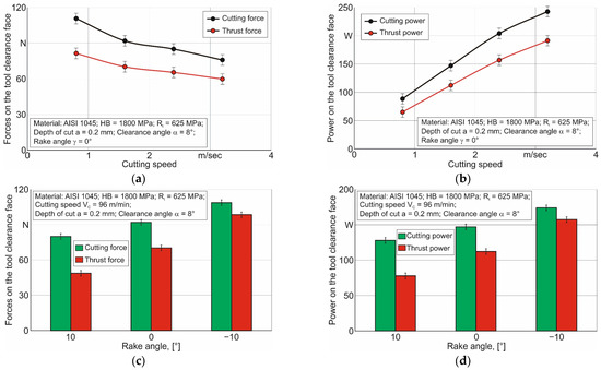
Figure 4.
Cutting forces and cutting power on the tool clearance face depending on the cutting speed and the tool rake angle: (a) cutting forces depending on the cutting speed; (b) cutting power depending on the cutting speed; (c) cutting forces depending on the rake angle; (d) cutting power depending on the rake angle.
4.2. Mechanical Characteristics of Machined Subsurface Layers
As the mechanical characteristics of the workpiece subsurface layers are generated through the cutting process, the total indentation work W and the maximum indentation depth hmax are considered (see Section 3). The diagrams of multiple indenter penetration during instrumented nanoindentation of the workpiece machined surface at cutting speed VC = 96 m/min (1.6 m/s) and the tool rake angle γ = 0° exemplarily are shown in Figure 5. Similar indentation diagrams were obtained by testing the workpiece surfaces machined with all the studied values of cutting speeds and tool angles. Such diagrams are used to determine the total indentation work (see Section 3.1), which is then used to match the cutting power.
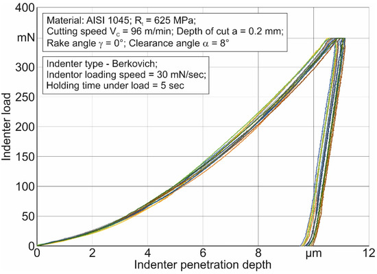
Figure 5.
Instrumented nanoindentation diagram.
The maximum indenter penetration depth is determined by a sclerometry test on the surface of the machined material. Figure 6 shows exemplarily the results of this test for a machined surface with a cutting speed of VC = 96 m/min (1.6 m/s) and a tool rake angle of γ = 0°. When the sclerometry test is carried out, the indenter is oriented with the tip forward along the sclerometry trace. The sclerometry diagram family at the specified parameters that is shown as an example in Figure 6a,b shows a part of the space image from one of the scratch families and the profile of this image. According to the sclerometry results, the greatest averaged depth of indentation over the family of scratches is determined (see also Section 3.1). This value is used later to match the cutting power at the tool clearance face.
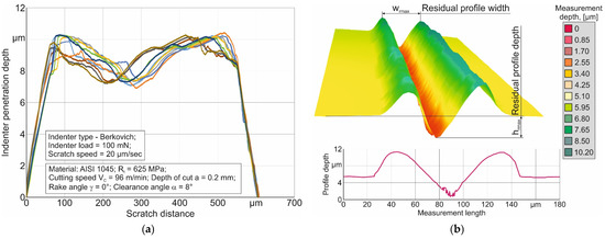
Figure 6.
Sclerometry results of the machined surface: (a) indenter penetration depth along the sclerometry distance; (b) image of the scratch profile (wmax—maximum scratch width).
The instrumented nanoindentation test described above (see Figure 5) was used to determine the total indenter work W for all studied values of cutting speeds and tool rake angles. In parallel, the microhardness of the workpiece surfaces processed using the orthogonal cutting process was determined. The dependences of the indentation work value and microhardness of the machined surface on the cutting speed and the tool rake angle are shown in Figure 7.
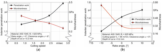
Figure 7.
Total indentation work and microhardness of machined surfaces: (a) depending on the cutting speed; (b) depending on the tool rake angle.
The indentation work increases with increasing cutting speed from 0.8 m/s to 2.4 m/s almost linearly—Figure 7a. A significantly greater increase in work W is observed at a cutting speed of 3.2 m/s. In all probability, this increase is explained by a significant increase in the cutting temperature at cutting speed VC = 3.2 m/s compared to the cutting temperature at lower cutting speeds. This leads to some softening in the subsurface layers of the machined workpiece. This is also evidenced by a decrease in the microhardness of the workpiece’s machined surface, the changed behavior of which, with increasing cutting speed, is similar to the changed behavior of the indenter introduction work. With the softening of the machined surface, the indenter penetration depth increases during instrumental nanoindentation of the studied surfaces. In turn, this leads to an increase in the penetration work W. Increasing the tool rake angle γ from −10° to 10° leads to an increase in the indentation work—Figure 7b. This changing character of the indentation work is explained by a decrease in the strain degree of the machined material with an increase in the tool rake angle. Reducing the strain degree of the machined material contributes to an increase in the indentation depth during instrumented indentation of the machined workpiece surface and, accordingly, increases the indentation work. With increasing tool rake angle, the microhardness of the machined workpiece surface decreases significantly (see Figure 7b). This also corresponds to the changed behavior of the strain degree in the subsurface layers of the machined material.
The sclerometry test of machined workpiece surfaces with the determination of the maximum indentation depth hmax (see Figure 6) was performed by testing the workpiece surfaces machined with all the studied values of cutting speeds and tool rake angles. The dependence of the maximum indentation depth on the cutting speed and the tool rake angle is shown in Figure 8. The maximum indenter penetration depth during sclerometry significantly increases with increasing cutting speed—Figure 8a. This change in the character of the indenter penetration depth corresponds to a certain softening of the machined material due to an increase in cutting temperature with an increase in the cutting speed. The maximum indenter penetration depth increases with the increasing tool rake angle—Figure 8b. This is quite logical since an increase in the tool rake angle causes a decrease in the strain degree of the machined subsurface layers. A smaller strain degree in the subsurface layers causes an increase in the indenter penetration depth when the scratch is applied to the workpiece’s machined surface.
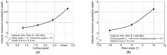
Figure 8.
Indenter penetration depth during sclerometry: (a) depending on cutting speed; (b) depending on tool rake angle.
The dependence shape of the total indentation work in instrument nanoindentation on the cutting speed (see Figure 7a) is similar to the dependence shape of the maximum indentation depth in sclerometry on the cutting speed (see Figure 8a). In all likelihood, this can be explained by the fact that the basis of these two dependencies is the same physical process of machined material softening with increasing the cutting speed. The change range of cutting speed is maintained for both of the studied mechanical characteristics: the total indentation work and its maximum penetration depth. To the same degree, the dependence shape of these two characteristics on the cutting speed is saved. The numerical dependence of these characteristics on the cutting speed is, of course, different. This difference is caused naturally by the different physical nature of the studied characteristics.
5. Discussion
Analyzing the results of instrumental nanoindentation and sclerometry of workpiece surfaces machined at different cutting speeds and using different tool rake angles indicates a significant influence of cutting conditions on the mechanical characteristics of the machined material’s subsurface layers. This gives the basis for further use of the postulate formulated above (see Section 3.2) in evaluating the effect of the cutting process on the mechanical characteristics of the machined material’s subsurface layers. For this purpose, a comparison of the cutting power in the tertiary cutting zone with the indenter penetration work and its penetration depth was performed.
Figure 9 shows the dependencies of indentation work as a result of the instrumented nanoindentation of machined workpiece surfaces at different cutting speeds and different tool rake angles. The increase in cutting power causes a directly proportional increase in the indenter penetration work in the region of increasing cutting speed from 0.8 m/s to 2.4 m/s. When the cutting power is further increased, in the region of cutting speed equal to 3.2 m/s, the indenter penetration work increases to a significantly greater extent—Figure 9a. The microhardness of the workpiece’s machined surfaces is related to the increase in cutting power in the tertiary cutting zone by an inversely proportional relationship (see Figure 9a). When the cutting power increases due to the growth of cutting forces on the tool clearance face caused by a decrease in the tool rake angle, the indenter penetration work decreases accordingly. In parallel, the microhardness of machined workpiece surfaces increases with increasing cutting power—Figure 9b.
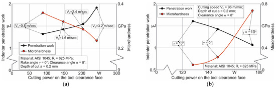
Figure 9.
The coincidence of the total indenter penetration work with the cutting energy on the tool clearance face: (a) depending on the cutting speed; (b) depending on the tool rake angle.
Dependences of the maximum indenter penetration depth during scratching (sclerometry) on the cutting power on the tool clearance face are shown in Figure 10. With increasing the cutting power due to increasing cutting speed, the maximum depth of indenter penetration increases—Figure 10a. This increase is almost the same over the entire range of cutting speeds. An increase in cutting power due to an increase in cutting forces, which in turn is caused by a decrease in the tool rake angle, leads to a decrease in the maximum penetration depth of the indenter—Figure 10b.
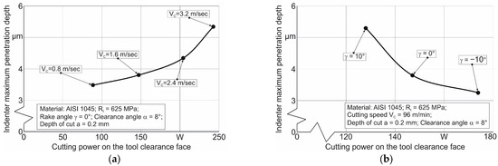
Figure 10.
The coincidence of indenter penetration depth during sclerometry with the cutting energy on the tool clearance face: (a) depending on the cutting speed; (b) depending on the tool rake angle.
When analyzing the influence of cutting power in the tertiary zone on the indentation work as a result of instrumental nanoindentation, as well as when analyzing the influence of cutting power on the maximum indentation depth as a result of scratching the machined surface, it is necessary to take into account the cutting conditions that cause cutting power changes in each specific case. For example, it is necessary to consider whether the increase in cutting power is caused by an increase in cutting speed or by an increase in cutting forces.
Thus, if it is necessary to determine the cause of changes in the integral mechanical characteristics of the workpiece’s subsurface layers processed through the cutting process, thermomechanical analysis of the interaction between the tool and the workpiece should be performed in parallel with micro- and nanomechanical tests of the machined subsurface layers.
6. Conclusions
The indenter penetration work during instrumented nanoindentation and the maximum indenter penetration depth during sclerometry are proposed to be applied as mechanical characteristics of the machined subsurface layers.
Increasing the cutting speed and increasing the tool rake angle causes an increase in the indenter penetration work during instrumented nanoindentation and an increase in the maximum indenter depth during sclerometry. Increasing the cutting power in the tertiary cutting zone (on the tool clearance face) also causes an increase in the indenter penetration work during instrumented nanoindentation and its maximum penetration depth during sclerometry. In parallel, the measured microhardness of the machined surfaces decreases with both an increase in cutting speed and an increase in the tool rake angle.
The reasons for cutting power changes may be the basis for interpreting the mechanical properties’ behavior of the machined workpiece subsurface layers with changes in the cutting process conditions and evaluating this effect.
The considered integral characteristics of the machined subsurface layers can be used to evaluate the influence of machining conditions on the physical–mechanical state of these layers. This possibility is ensured due to the close connection between the thermomechanical interaction of the tool and the machined material with the physical–mechanical state of the material generated as a result of the cutting process.
Funding
This study was funded by the German Research Foundation (DFG) in the project HE-1656/153-1 “Development of a Concept for Determining the Mechanical Properties of the Cutting Material in Machining”.
Data Availability Statement
Not applicable.
Acknowledgments
The author would like to thank the German Research Foundation (DFG) for their support, which is highly appreciated.
Conflicts of Interest
The author declares no conflict of interest.
References
- Guo, Y.; Saldana, C.; Compton, W.D.; Chandrasekar, S. Controlling deformation and microstructure on machined surfaces. Acta Mater. 2011, 59, 4538–4547. [Google Scholar] [CrossRef]
- Saptaji, K.; Afiqah, S.N.; Ramdan, R.D. A Review on Measurement Methods for Machining Induced Residual Stress. Indones. J. Comput. Eng. Des. 2019, 1, 106–120. [Google Scholar] [CrossRef]
- Pharr, G.M. Recent advances in small-scale mechanical property measurement by nanoindentation. Curr. Opin. Solid State Mater. Sci. 2015, 19, 315–316. [Google Scholar] [CrossRef]
- Voyiadjis, G.Z.; Yaghoobi, M. Review of Nanoindentation Size Effect: Experiments and Atomistic Simulation. Crystals 2017, 7, 321. [Google Scholar] [CrossRef]
- Wredenberg, F.; Larsson, P.-L. Scratch testing of metals and polymers: Experiments and numerics. Wear 2009, 266, 76–83. [Google Scholar] [CrossRef]
- Fischer-Cripps, A.C. Critical review of analysis and interpretation of nanoindentation test data. Surf. Coat. Technol. 2006, 200, 4153–4165. [Google Scholar] [CrossRef]
- Li, X.; Bhushan, B. A review of nanoindentation continuous stiffness measurement technique and its applications. Mater. Charact. 2002, 48, 11–36. [Google Scholar] [CrossRef]
- Kolawole, O.; Ispas, I. Evaluation of geomechanical properties via scratch tests: Where are we and where do we go from here? SN Appl. Sci. 2020, 2, 1633. [Google Scholar] [CrossRef]
- Atkins, A.; Tabor, D. Plastic indentation in metals with cones. J. Mech. Phys. Solids 1965, 13, 149–164. [Google Scholar] [CrossRef]
- Pethicai, J.B.; Hutchings, R.; Oliver, W.C. Hardness measurement at penetration depths as small as 20 nm. Philos. Mag. A 1983, 48, 593–606. [Google Scholar] [CrossRef]
- Fischer-Cripps, A.C. Nanoindentation of thin films and small volumes of materials. In Nanoindentation, 2nd ed.; Springer: Berlin/Heidelberg, Germany, 2011; 276p. [Google Scholar] [CrossRef]
- Doerner, M.F.; Nix, W.D. A method for interpreting the data from depth-sensing indentation instruments. J. Mater. Res. 1986, 1, 601–609. [Google Scholar] [CrossRef]
- Oliver, W.C.; Pharr, G.M. An improved technique for determining hardness and elastic modulus using load and displacement sensing indentation experiments. J. Mater. Res. 1992, 7, 1564–1583. [Google Scholar] [CrossRef]
- Vargas, A.L.M.; Blando, E.; Hübler, R. Elasto–Plastic materials behavior evaluation according to different models applied in indentation hardness tests. Measurement 2019, 139, 134–139. [Google Scholar] [CrossRef]
- Kang, J.J.; Becker, A.A.; Wen, W.; Sun, W. Extracting elastic-plastic properties from experimental loading-unloading indentation curves using different optimization techniques. Int. J. Mech. Sci. 2018, 144, 102–109. [Google Scholar] [CrossRef]
- Guillonneau, G.; Kermouche, G.; Bec, S.; Loubet, J.-L. Determination of mechanical properties by nanoindentation independently of indentation depth measurement. J. Mater. Res. 2012, 27, 2551–2560. [Google Scholar] [CrossRef]
- Harsono, E.; Swaddiwudhipong, S.; Liu, Z.S. The effect of friction on indentation test results. Model. Simul. Mater. Sci. Eng. 2008, 16, 065001. [Google Scholar] [CrossRef]
- Wang, Y. Effects of indenter angle and friction on the mechanical properties of film materials. Results Phys. 2016, 6, 509–514. [Google Scholar] [CrossRef]
- Sivaram, S.; Jayasinghe, J.A.S.C.; Bandara, C.S. Qualitative Study on Pile-up Effect on Hardness Test by Nano-Indentation. Eng. J. Inst. Eng. Sri Lanka 2021, 54, 47. [Google Scholar] [CrossRef]
- Tsybenko, H.; Farzam, F.; Dehm, G.; Brinckmann, S. Scratch hardness at a small scale: Experimental methods and correlation to nanoindentation hardness. Tribol. Int. 2021, 163, 107168. [Google Scholar] [CrossRef]
- Dean, J.; Aldrich-Smith, G.; Clyne, T.W. Use of nanoindentation to measure residual stresses in surface layers. Acta Mater. 2011, 59, 2749–2761. [Google Scholar] [CrossRef]
- Kanaev, A.T.; Ramazanova, Z.M.; Biizhanov, S.K. Study of plasma-hardened wheel steel using nanoindentation. Ind. Lab. Diagn. Mater. 2020, 86, 56–60. (In Russian) [Google Scholar] [CrossRef]
- England, J.; Uddin, M.J.; Ramirez-Cedillo, E.; Karunarathne, D.; Nasrazadani, S.; Golden, T.D.; Siller, H.R. Nanoindentation Hardness and Corrosion Studies of Additively Manufactured 316L Stainless Steel. J. Mater. Eng. Perform. 2022, 31, 6795–6805. [Google Scholar] [CrossRef]
- Oila, A.; Bull, S.J. Nanoindentation testing of gear steels. Int. J. Mater. Res. 2003, 94, 793–797. [Google Scholar] [CrossRef]
- Moon, J.; Kim, S.; Jang, J.-I.; Lee, J.; Lee, C. Orowan strengthening effect on the nanoindentation hardness of the ferrite matrix in microalloyed steels. Mater. Sci. Eng. A 2008, 487, 552–557. [Google Scholar] [CrossRef]
- Mendas, M.; Benayoun, S.; Miloud, M.H.; Zidane, I. Microhardness model based on geometrically necessary dislocations for heterogeneous material. J. Mater. Res. Technol. 2021, 15, 2792–2801. [Google Scholar] [CrossRef]
- Ameri, A.A.H.; Elewa, N.N.; Ashraf, M.; Escobedo-Diaz, J.P. General methodology to estimate the dislocation density from microhardness measurements. Mater. Charact. 2017, 131, 324–330. [Google Scholar] [CrossRef]
- Wang, H.; Zhu, L.; Xu, B. Residual Stresses and Nanoindentation Testing of Films and Coatings; Springer Nature Singapore Pte Ltd. and Science Press: Beijing, China, 2018; 207p, ISBN 978-981-10-7840-8. [Google Scholar] [CrossRef]
- Zhang, W.; Wang, X.; Hu, Y.; Wang, S. Predictive modelling of microstructure changes, micro-hardness and residual stress in machining of 304 austenitic stainless steel. Int. J. Mach. Tools Manuf. 2018, 130–131, 36–48. [Google Scholar] [CrossRef]
- Ding, K.; Zhang, Y.; Birnbaum, A.J.; Michopoulos, J.G.; McDowell, D.L.; Zhu, T. Strain gradient plasticity modeling of nanoindentation of additively manufactured stainless steel. Extrem. Mech. Lett. 2021, 49, 101503. [Google Scholar] [CrossRef]
- Lin, P.; Nie, J.; Liu, M. Nanoindentation experiment and crystal plasticity study on the mechanical behavior of Fe-ion-irradiated A508-3 steel. J. Nucl. Mater. 2022, 571, 154002. [Google Scholar] [CrossRef]
- Li, C.; Zhao, H.; Sun, L.; Yu, X. In situ nanoindentation method for characterizing tensile properties of AISI 1045 steel based on mesomechanical analysis. Adv. Mech. Eng. 2019, 11, 1–11. [Google Scholar] [CrossRef]
- Paul, V.; Ameyama, K.; Ota-Kawabata, M.; Ohmura, T. Evaluation of Deformation and Fracture Behavior in 304L Austenitic Steel Harmonic Structures through Nanoindentation. Steel Res. Int. 2023, 94, 2200354. [Google Scholar] [CrossRef]
- Yang, L.; Sun, K.; Peng, W.; Li, X.; Zhang, L. Effects of Grain Boundary Angles on Initial Deformation of 304 Austenitic Stainless Steel under Nanoindentation: A Molecular Dynamics Simulation. Crystals 2022, 12, 58. [Google Scholar] [CrossRef]
- Zhou, G.; Guo, J.; Zhao, J.; Tang, Q.; Hu, Z. Nanoindentation Properties of 18CrNiMo7-6 Steel after Carburizing and Quenching Determined by Continuous Stiffness Measurement Method. Metals 2020, 10, 125. [Google Scholar] [CrossRef]
- Wagner, R.; Lehnert, R.; Storti, E.; Ditscherlein, L.; Schröder, C.; Dudczig, S.; Peuker, U.A.; Volkova, O.; Aneziris, C.G.; Biermann, H.; et al. Nanoindentation of alumina and multiphase inclusions in 42CrMo4 steel. Mater. Charact. 2022, 193, 112257. [Google Scholar] [CrossRef]
- Bobzin, K.; Kalscheuer, C.; Carlet, M.; Schmauder, S.; Guski, V.; Verestek, W.; Tayyab, M. 3D deformation modeling of CrAlN coated tool steel compound during nanoindentation. Surf. Coat. Technol. 2023, 453, 129148. [Google Scholar] [CrossRef]
- Khan, M.K.; Hainsworth, S.V.; Fitzpatrick, M.E.; Edwards, L. A combined experimental and finite element approach for determining mechanical properties of aluminium alloys by nanoindentation. Comput. Mater. Sci. 2010, 49, 751–760. [Google Scholar] [CrossRef]
- Han, G.; Marimuthu, K.P.; Lee, H. Evaluation of thin film material properties using a deep nanoindentation and ANN. Mater. Des. 2022, 221, 111000. [Google Scholar] [CrossRef]
- Wittler, O.; Mrossko, R.; Kaulfersch, E.; Wunderle, B.; Michel, B. Mechanical characterisation of thin metal layers by modelling of the nanoindentation experiment. In Proceedings of the 2nd Electronics System-Integration Technology Conference, Greenwich, UK, 1–4 September 2008; pp. 995–998. [Google Scholar] [CrossRef]
- Pöhl, F. Determination of unique plastic properties from sharp indentation. Int. J. Solids Struct. 2019, 171, 174–180. [Google Scholar] [CrossRef]
- Peng, G.; Xu, F.; Chen, J.; Hu, Y.; Wang, H.; Zhang, T. A cost-effective voice coil motor-based portable micro-indentation device for in situ testing. Measurement 2020, 165, 108105. [Google Scholar] [CrossRef]
- Li, Z.; Herrmann, K.; Pohlenz, F. A comparative approach for calibration of the depth measuring system in a nanoindentation instrument. Measurement 2006, 39, 547–552. [Google Scholar] [CrossRef]
- Fritz, R.; Kiener, D. Development and application of a heated in-situ SEM micro-testing device. Measurement 2017, 110, 356–366. [Google Scholar] [CrossRef]
- Randall, N.X. The current state-of-the-art in scratch testing of coated systems. Surf. Coat. Technol. 2019, 380, 125092. [Google Scholar] [CrossRef]
- Li, J.; Beres, W. Scratch Test for Coating/Substrate Systems—A Literature Review. Can. Met. Q. 2007, 46, 155–173. [Google Scholar] [CrossRef]
- Lin, C.K.; Berndt, C.C. Measurement and analysis of adhesion strength for thermally sprayed coatings. J. Therm. Spray Technol. 1994, 3, 75–104. [Google Scholar] [CrossRef]
- Bull, S.J. Failure modes in scratch adhesion testing. Surf. Coat. Technol. 1991, 50, 25–32. [Google Scholar] [CrossRef]
- Zivica, F.; Babic, M.; Adamovic, D.; Mitrovic, S.; Todorovic, P.; Favarob, G.; Pantic, M. Influence of the surface roughness on adhesion of chrome coatings on alloy tool steel x165crmov12. J. Balk. Tribol. Assoc. 2012, 18, 228–237. [Google Scholar]
- Sousa, F.J.P.; Tridapalli, D.; Pereira, M.; Flesch, C.A.; Alarcon, O.E. Evaluation of measurement uncertainties for a scratching tester. Measurement 2006, 39, 594–604. [Google Scholar] [CrossRef]
- Yildiz, F.; Alsaran, A. Multi-pass scratch test behavior of modified layer formed during plasma nitriding. Tribol. Int. 2010, 43, 1472–1478. [Google Scholar] [CrossRef]
- Storchak, M.; Zakiev, I.; Zakiev, V.; Manokhin, A. Coatings strength evaluation of cutting inserts using advanced multi-pass scratch method. Measurement 2022, 191, 110745. [Google Scholar] [CrossRef]
- Farayibi, P.; Hankel, J.; Hassend, F.v.G.; Blüm, M.; Weber, S.; Röttger, A. Tribological characteristics of sintered martensitic stainless steels by nano-scratch and nanoindentation tests. Wear 2023, 512, 204547. [Google Scholar] [CrossRef]
- Aurich, J.C.; Steffes, M. Single Grain Scratch Tests to Determine Elastic and Plastic Material Behavior in Grinding. Adv. Mater. Res. 2011, 325, 48–53. [Google Scholar] [CrossRef]
- Fan, P.; Katiyar, N.K.; Zhou, X.; Goel, S. Uniaxial pulling and nano-scratching of a newly synthesized high entropy alloy. APL Mater. 2022, 10, 111118. [Google Scholar] [CrossRef]
- Pratap, A.; Divse, V.; Goel, S.; Joshi, S.S. Understanding the surface generation mechanism during micro-scratching of Ti-6Al-4V. J. Manuf. Process. 2022, 82, 543–558. [Google Scholar] [CrossRef]
- Liu, H.; Xu, X.; Zhang, J.; Liu, Z.; He, Y.; Zhao, W.; Liu, Z. The state of the art for numerical simulations of the effect of the microstructure and its evolution in the metal-cutting processes. Int. J. Mach. Tools Manuf. 2022, 177, 103890. [Google Scholar] [CrossRef]
- Bezyazichnyy, V.; Rybinsk State Aviation Technical University; Prokofiev, M.; Vinogradova, N. Research of the Influence of Technological Machining Conditions on the Accumulation of Latent Energy Deformation in the surface Parts. Bull. PNIPU Aerosp. Eng. 2015, 43, 131–144. [Google Scholar] [CrossRef]
- Yamamoto, M.; Tanaka, M.; Furukimi, O. Hardness–Deformation Energy Relationship in Metals and Alloys: A Comparative Evaluation Based on Nanoindentation Testing and Thermodynamic Consideration. Materials 2021, 14, 7217. [Google Scholar] [CrossRef]
- Ren, X.; Liu, Z. Influence of cutting parameters on work hardening behavior of surface layer during turning superalloy Inconel 718. Int. J. Adv. Manuf. Technol. 2016, 86, 2319–2327. [Google Scholar] [CrossRef]
- Wang, Q.; Liu, Z.; Wang, B.; Song, Q.; Wan, Y. Evolutions of grain size and micro-hardness during chip formation and machined surface generation for Ti-6Al-4V in high-speed machining. Int. J. Adv. Manuf. Technol. 2016, 82, 1725–1736. [Google Scholar] [CrossRef]
- Kushner, V.; Storchak, M. Determining mechanical characteristics of material resistance to deformation in machining. Prod. Eng. 2014, 8, 679–688. [Google Scholar] [CrossRef]
- Heisel, U.; Kushner, V.; Storchak, M. Effect of machining conditions on specific tangential forces. Prod. Eng. 2012, 6, 621–629. [Google Scholar] [CrossRef]
- Heisel, U.; Storchak, M.; Krivoruchko, D. Thermal effects in orthogonal cutting. Prod. Eng. 2013, 7, 203–211. [Google Scholar] [CrossRef]
- Filatov, Y.D.; Filatov, A.Y.; Syrota, O.O.; Yashchuk, V.P.; Monteil, G.; Heisel, U.; Storchak, M. The influence of tool wear particles scattering in the contact zone on the workpiece surface microprofile formation in polishing quartz. J. Superhard Mater. 2010, 32, 415–422. [Google Scholar] [CrossRef]
- Filatov, Y.D.; Sidorko, V.I.; Filatov, O.Y.; Yaschuk, V.P.; Heisel, U.; Storchak, M. Surface quality control in diamond abrasive finishing. Proc. SPIE 2009, 7389, 73892O. [Google Scholar] [CrossRef]
- Villarrazo, N.; Caneda, S.; Pereira, O.; Rodríguez, A.; López de Lacalle, L.N. The Effects of Lubricooling Ecosustainable Techniques on ToolWear in Carbon Steel Milling. Materials 2023, 16, 2936. [Google Scholar] [CrossRef]
- Storchak, M.; Stehle, T.; Möhring, H.-C. Determination of thermal material properties for the numerical simulation of cutting processes. Int. J. Adv. Manuf. Technol. 2021, 118, 1941–1956. [Google Scholar] [CrossRef]
- Storchak, M.; Jiang, L.; Xu, Y.; Li, X. Finite element modeling for the cutting process of the titanium alloy Ti10V2Fe3Al. Prod. Eng. 2016, 10, 509–517. [Google Scholar] [CrossRef]
- Storchak, M.; Zakiev, I.; Träris, L. Mechanical properties of subsurface layers in the machining of the titanium alloy Ti10V2Fe3Al. J. Mech. Sci. Technol. 2018, 32, 315–322. [Google Scholar] [CrossRef]
- Zorev, N.N. Metal Cutting Mechanics; Pergamon Press GmbH: Frankfurt am Main, Germany, 1966; 526p. [Google Scholar]
- Oxley, P.L.B. Development and Application of a Predictive Machining Theory. Mach. Sci. Technol. 1998, 2, 165–189. [Google Scholar] [CrossRef]
- Kushner, V.; Storchak, M. Modelling the material resistance to cutting. Int. J. Mech. Sci. 2017, 126, 44–54. [Google Scholar] [CrossRef]
- Kushner, V.; Storchak, M. Determination of Material Resistance Characteristics in Cutting. Procedia CIRP 2017, 58, 293–298. [Google Scholar] [CrossRef]
- Tsekhanov, J.; Storchak, M. Development of analytical model for orthogonal cutting. Prod. Eng. 2015, 9, 247–255. [Google Scholar] [CrossRef]
- Storchak, M.; Möhring, H.-C.; Stehle, T. Improving the friction model for the simulation of cutting processes. Tribol. Int. 2022, 167, 107376. [Google Scholar] [CrossRef]
- Storchak, M.; Mohring, H.-C. Numerical and Experimental Analysis of Chip Formation at Ultrahigh Cutting Speed. MM Sci. J. 2019, 2019, 3243–3249. [Google Scholar] [CrossRef]


Disclaimer/Publisher’s Note: The statements, opinions and data contained in all publications are solely those of the individual author(s) and contributor(s) and not of MDPI and/or the editor(s). MDPI and/or the editor(s) disclaim responsibility for any injury to people or property resulting from any ideas, methods, instructions or products referred to in the content. |
© 2023 by the author. Licensee MDPI, Basel, Switzerland. This article is an open access article distributed under the terms and conditions of the Creative Commons Attribution (CC BY) license (https://creativecommons.org/licenses/by/4.0/).