1. Introduction
At present, traditional Sn-Pb solders have been forbidden due to their toxicity, in violation of the Regulation of Hazardous Substances and Waste Electrical and Electronic Equipment regulations. This has led to the rapid development of lead-free solder [
1], of which there are many types. Generally, tin is used as the base metal, and the common ones are Sn-Bi, Sn-Cu, Sn-Zn, Sn-Ag-Cu, etc. [
2,
3,
4,
5]. However, they face some challenges compared to Sn-Pb solders, such as poor wetting, a higher soldering temperature, and unsatisfactory mechanical properties [
6]. Alloying or particle-strengthening methods can address these shortcomings [
7]. In particular, doped nanomaterials have attracted significant interest in developing high-performance tin-based, lead-free solders [
8,
9,
10].
Carbon nanotubes (CNTs) are promising nanomaterials that are attractive components in composite solder applications due to their excellent mechanical, electrical, and thermal properties [
11,
12]. The mechanical properties of composite solders have been significantly improved by using CNTs [
13,
14]. In CNT-based composite solders, CNTs can be roughly divided into unmodified CNTs and metal-modified CNTs [
15,
16]. The following main processing methods have been widely used to combine CNTs and solders: mechanical mixing, powder metallurgy (P/M), and electrochemical deposition [
17,
18,
19]. The former two are to mix CNTs directly with solder by physical means, and the latter is to deposit and embed CNTs in the solder matrix by chemical means.
Although some research results have been obtained, CNT composite solder still has several deficiencies, such as uneven dispersion of CNTs, structural damage, limited addition amounts, and low bonding strengths with solder substrates. In addition, due to the high cost and complicated preparation of CNT-reinforced composite solder, it has not been practically applied in industrial production. Some reviews of CNT composite solders have been reported. In previous years, Zhang et al. [
20] reviewed the influence of various nanoparticles, including CNTs, on the structure and properties of solder. Recently, Tian et al. [
21] also reviewed the enhancement of solder by different nanoparticles and mainly focused on discussing the reliability of composite solder. However, due to the many types of nanoparticles involved in these two studies, there is less content about CNT-enhanced solder alone. Additionally, it is limited to discussing the influence of CNTs on the mechanical properties of solder. As a result, it is essential to make a systematic summary of the influence of CNTs on various properties of solder.
In this paper, the microstructure, strengthening mechanism, and preparation method of CNT composite solders are first introduced. Then, the effects of unmodified CNTs and metal-modified CNTs on the mechanical, thermal, and electrical properties of solder were analyzed and summarized. In the last section, the future direction of CNT-enhanced solder research is discussed. This review aims to provide a theoretical basis for the development of high-performance CNT composite solders. It is hoped that this effort will contribute to the further development of the application of CNTs in solder.
2. Structure of CNT Composite Solder
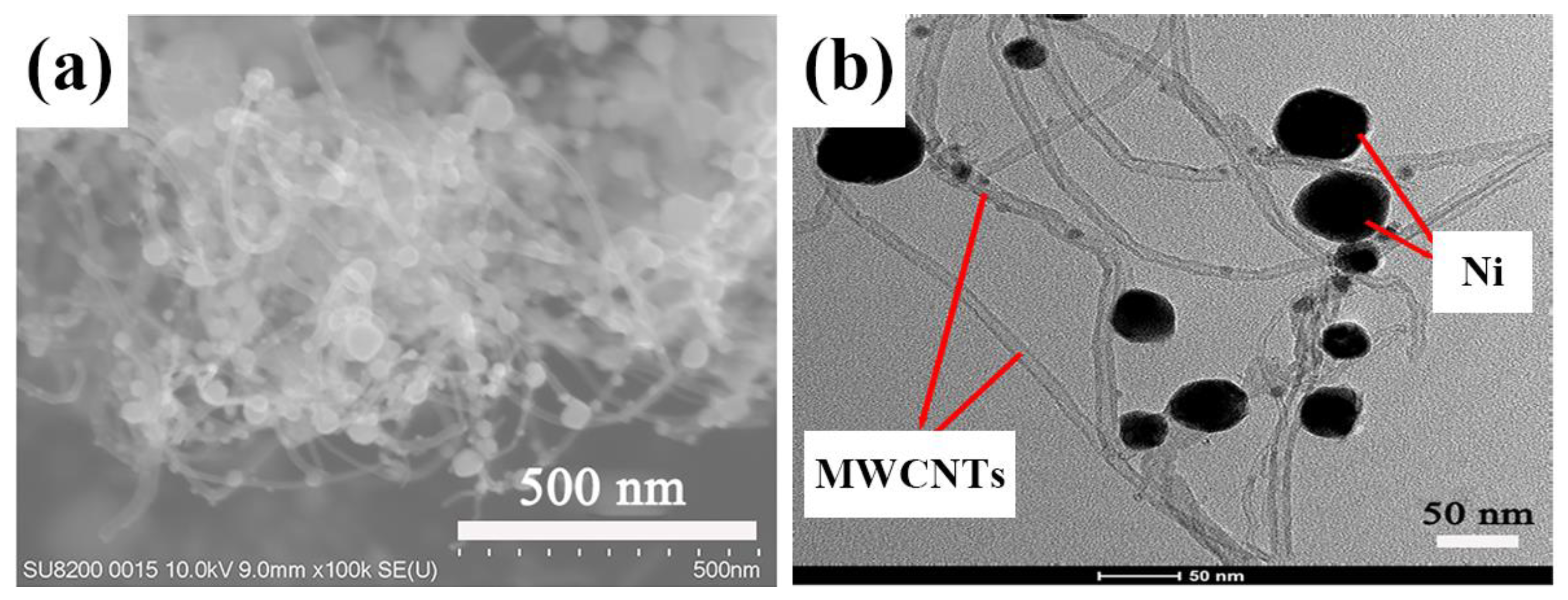
In general, it is difficult to directly observe the structure of CNTs in composite solders due to the small amount of CNTs added. Most studies reported the structure before CNTs were added to the solder, as shown in
Figure 1 [
22], while few studies reported the structure after CNTs were added to the solder. Considering that agglomeration is easy to cause crack initiation, theoretically, the structure of CNTs in solder can be indirectly observed on the fracture surface.
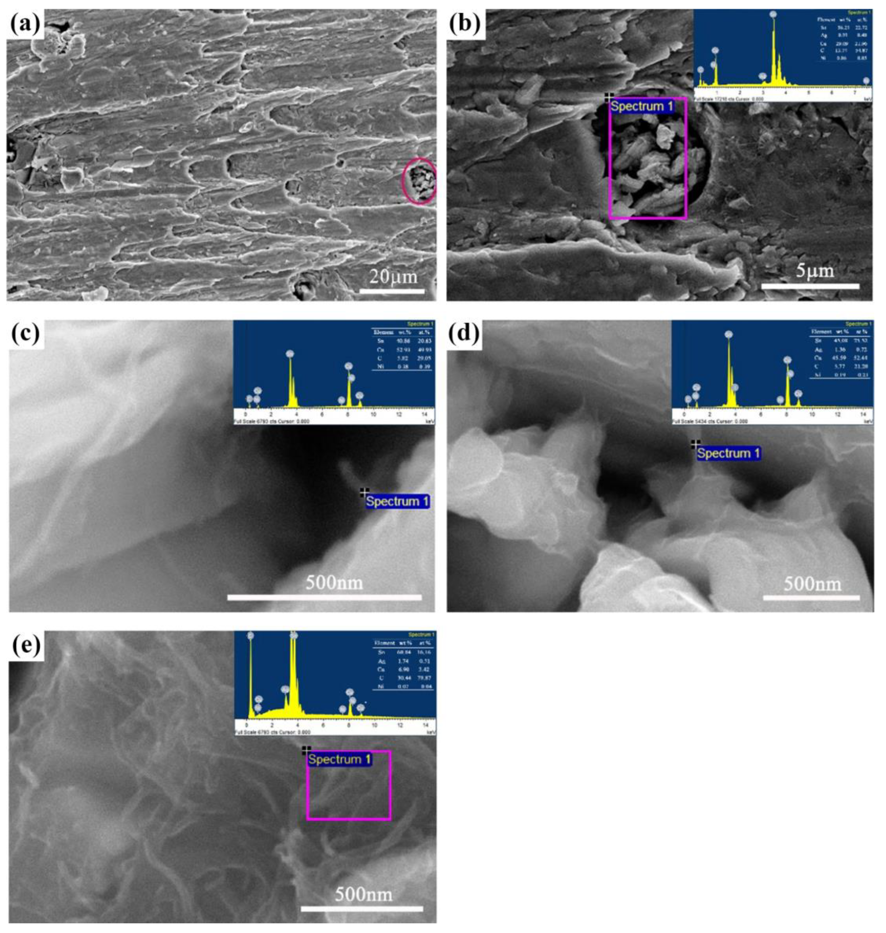
Figure 2 [
23] depicts the fracture morphology of Sn-3.0Ag-0.5Cu (SAC305) composite solder joints containing 0.5 wt.% Ni-modified carbon nanotubes (Ni-CNTs) aged for 96 h. Enlarge the dimple circled by the purple ellipse on the right side of
Figure 2a and perform energy-dispersive X-ray spectroscopy analysis, as shown in
Figure 2b. The presence of Ni-CNTs was observed. The selected area is further enlarged, and the morphology of Ni-CNTs is shown in
Figure 2c, where it can be seen that although the Ni-CNTs have been fractured, one end is still embedded in the solder matrix. There are also some Ni-CNTs that still serve as bridges to connect the separated parts into a whole after the composite solder joint breaks, as shown in
Figure 2d. It can be seen from
Figure 2e that the structure of Ni-CNTs in the composite solder has not changed significantly. However, the Ni-CNTs are entangled haphazardly, which indicates that fractures tend to occur where there are agglomerates. The above is because CNTs are embedded in the solder matrix, so CNTs may be observed at the fracture surface. If, as shown in
Figure 3 [
24], a large number of multi-walled carbon nanotubes (MWCNTs) are discharged to the solder surface due to their low density during the reflow process, it is not necessarily possible to find the presence of MWCNTs on the fracture surface.
3. Strengthening Mechanism of CNT Composite Solder
The use of CNTs to enhance solder has become a research hotspot. It is essential to understand their strengthening mechanisms to facilitate the development of CNT composite solders. So far, many strengthening mechanisms of CNTs have been reported, and the widely accepted ones mainly include the following four [
25,
26,
27]: (1) load transfer strengthening; (2) dislocation interference strengthening (Orowan strengthening); (3) mismatch strengthening; and (4) fine grain strengthening. These mechanisms synergistically reinforce the matrix [
28].
First, load transfer means that when the composite solder is loaded, the interfacial stress will be transferred to the CNTs dispersed in the matrix. Due to the excellent mechanical properties of CNTs, they can bear most of the stress. Ismail et al. [
29] explained this mechanism through experimental results, showing that adding CNTs prevents sudden changes in the deformation mechanism in solder under shock waves. Compared with the SAC305 solder joints of the explosion test samples and the control samples, the indentation depth displacements of the SAC305-CNTs solder joints of the explosion test samples and the control samples were reduced by about 42% and 56%, respectively. The load transfer effect of CNTs was also reflected in the finite element simulation results, as the location of maximum stress intensity was shifted from the solder at the interface edge to the CNTs [
30]. Additionally, the interfacial bonding strength between CNTs and the solder matrix is crucial to load transfer strengthening. Literature studies have shown that the load cannot be transferred from the Sn-3.5Ag-0.7Cu (SAC357) solder matrix to Ni-modified multi-walled carbon nanotubes (Ni-MWCNTs) when the interfacial bonding strength is insufficient [
31].
Second, CNTs are inert materials that do not react with elements in the solder matrix and have a melting point much higher than the soldering temperature [
32,
33]. Thus, CNTs can function as pinning sites. It has been reported that the yield strength of the composite solder was increased by 17.52% compared with the original Sn-0.7Cu solder when Ni-CNTs were added in an amount of 0.075 wt.% [
34]. This is because when the addition amount is less than 0.075 wt.%, Ni-CNTs are dispersed in the solder as the second phase, effectively hindering the movement of dislocations.
Third, the thermal modulus, elastic modulus, or geometric mismatch between the solder matrix and the reinforcement CNTs can induce plastic deformation, making dislocations multiply. Nai et al. [
35] showed that the high dislocation density in the matrix could be attributed to the significant difference in thermal expansion coefficient between SAC357 solder and MWCNTs. They also expressed similar views in other research results, arguing that the geometrically necessary dislocations are generated to accommodate the thermal elastic modulus mismatch between solder and MWCNTs [
36].
Finally, CNTs are usually dispersed at grain boundaries in the solder matrix, inhibiting grain growth. As a result, the number of grains per unit volume increases, the stress concentration decreases when a force is applied, and the grain boundary area increases, hindering the movement of dislocations [
37]. According to the study by Zhu et al. [
38], MWCNTs refine the microstructure of the composite solder and increase the grain boundary density. Therefore, the movement of dislocations is hindered microscopically, and the shear strength and hardness are improved macroscopically. However, due to the limitation of the amount of addition, the degree of grain refinement is limited. Compared with the initial solder, the average grain size of the SAC357 composite solder decreased by 6% under the influence of 0.1 wt.% Ni-MWCNTs and only 4.6% under the influence of 0.1 wt.% unmodified MWCNTs [
39].
4. Preparation Method of CNT Composite Solder
It is well known that a high specific surface area characterizes CNTs. This can easily lead to the agglomeration of CNTs and the formation of cracks or pores in the composite solder, thereby degrading the overall performance [
40]. Therefore, the primary challenge for CNT-enhanced solders is the dispersion of CNTs. Many researchers have carried out much research on how to make CNTs evenly distributed in the matrix and finally found that this problem can be improved by optimizing the preparation method [
41,
42,
43]. There are many methods for preparing CNT composite solder, and this article mainly introduces the most commonly used ones.
4.1. Mechanical Mixing Method
The mechanical mixing method is to disperse the reinforcing phase in the metal matrix by using a ball mill or an agitator. Long-term mechanical mixing can weaken the van der Waals force between CNTs, and the dispersion can be improved. Ismail et al. [
44] mixed CNTs with SAC305 solder and stirred them in a vacuum chamber for 2 h. Although they did not report on the dispersion of CNTs, they found that the mechanical properties of the composite solder were improved after the addition of CNTs. When exposed to the blast wave test of 1000 g of explosive, the hardness value of the initial solder decreased by about 23%, while that of SAC305-0.04CNTs only decreased by about 15%. This indirectly indicates that the mechanical mixing method helps to improve the dispersion of MWCNTs. Additionally, using the mechanical mixing method, Han et al. [
45] mixed the powder in a V-shaped mixer for 10 h. Finally, they obtained a SAC357 composite solder containing a dense Ni-MWCNTs corrosion-resistant layer. In addition, the flux is beneficial for dispersing the mixed solder evenly during the reflow process. Xu et al. [
46] added water-soluble flux according to the weight ratio of the flux to mixed solder (1:8.5) to achieve uniform distribution of MWCNTs in Sn-3.5Ag-0.5Cu solder. Additionally, with the help of 0.1 wt.% MWCNTs, the microhardness of the composite solder was improved by 12.4%. The mechanical mixing method is the most convenient method for preparing CNT composite solder, and the cost is not high, so it can be used for mass production of CNT composite solder. However, it is precisely because this method is so simple that it is difficult to effectively control the dispersion and damage of CNTs, which will easily lead to a decrease in the performance of the composite solder.
Figure 4a [
47] is the top view of the fracture surface of the Sn-58Bi composite solder joint containing 0.1 wt.% Sn-modified multi-walled carbon nanotubes (Sn-MWCNTs) after the shear test. The fracture was enlarged, and it was found that Sn-MWCNTs were successfully embedded in the solder matrix by mechanical mixing, as shown in
Figure 4b,c [
47]. In addition, the entanglement of Sn-MWCNTs was observed.
4.2. P/M Method
P/M [
48,
49] means that the alloy powder of the matrix and the reinforcing material are subjected to repeated deformation, cold welding, and crushing through ball milling to obtain a pre-alloyed mixed powder. It is then compressed into shape in a mold. Finally, the final product is obtained through a sintering process. The traditional P/M process is shown in
Figure 5 [
50]. The high-energy ball milling in the above procedure is called mechanical alloying (MA) [
51]. It is worth noting that the essential thing in the P/M process flow for preparing composite solder is MA. Although the impact force generated by MA may lead to structural damage to CNTs, most studies [
52,
53,
54] have shown that the uniform dispersion of CNTs in the matrix can be achieved by ball milling. The ball milling process, time, rotation speed, ball powder ratio, and process control agent have an important influence on the dispersion of CNTs.
Nai et al. [
55] were the first team to successfully prepare MWCNT-reinforced SAC357 composite solder using the traditional P/M method. They observed that the contact angle decreased by 15.7% and 19.8% when MWCNTs were added at 0.04 and 0.07 wt.%, respectively. It has been reported that surfactants can effectively improve dispersion by reducing the surface tension of CNTs [
56,
57]. Other researchers said ultrasonic assistance also helps uniformly disperse CNTs [
58]. These findings were further confirmed by Xu et al. [
46] and Vaisman et al. [
59]. Compared with the mechanical mixing method, the P/M method has also been widely used in preparing composite solder because it can produce solder with a specific shape while ensuring uniform distribution of CNTs and high strength. However, some researchers found that CNT dispersion still failed to meet expectations. Dele-Afolabi and his colleagues prepared Sn-5Sb-xMWCNTs (x = 0, 0.01, 0.05, and 0.1 wt.%) composite solders by the P/M method [
60]. They pointed out that MWCNTs agglomerate in the solder matrix when their content exceeds 0.05 wt.%. Although using surfactants or ultrasonic-assisted P/M has been proven effective in improving the dispersion of CNTs, these methods may cause damage to CNTs and are more likely to introduce defects, eventually leading to a decline in all-around performance [
27].
4.3. Electrochemical Deposition Method
Since the two physical methods of mechanical mixing and the P/M method are not ideal for improving the dispersion of CNTs, researchers began to consider chemical methods. They thus proposed a new preparation method: the electrochemical deposition method. In brief, the electrochemical deposition method mainly reduces and deposits metal ions on the electrode surface. At the same time, inert particles are adsorbed on the deposited metal surface. The electrochemical deposition method can be roughly divided into electrodeposition and chemical deposition methods, as shown in
Figure 6 and
Figure 7, respectively [
61]. The difference between these two methods is that the electrodeposition method requires an external voltage. In contrast, the chemical deposition method does not require an external energy source and only relies on a reducing agent or catalyst to reduce metal ions. In some literature, the electrochemical deposition method is called the electrochemical co-deposition method [
19]. It is only to distinguish whether a single-element coating or an alloy coating of multiple elements is formed on the electrode.
Choi et al. [
62] prepared Sn-MWCNT composite solder by electrodeposition. The shear energy of the composite solder is significantly enhanced because the MWCNTs embedded in the Sn matrix exhibit good dispersion, allowing efficient load transfer. Compared with the mechanical mixing method and the P/M method, which easily cause damage to CNTs, the electrochemical deposition method can ensure the integrity of the CNT structure and form a uniform CNT coating on the metal surface because it is carried out in a solution. This means that the dispersion of CNT composite solder prepared by electrochemical deposition is often better. Nevertheless, there are few studies on the preparation of CNT composite solder by electrochemical deposition, mainly due to the complexity of the method and the difficulty in determining the specific content deposited into the solder. Gadde et al. [
63] ground MWCNTs for 1 h and then activated them with HNO3. Finally, the carbon content of the composite film obtained by electrodeposition was about 1.4%. Still, they estimated MWCNTs to account for about 0.5% of the film and did not determine the specific content.
5. Composite Solder Reinforced with Different Types of CNTs
Different types of CNTs have been used in solders, which can be divided into two categories: (1) unmodified CNT composite solders and (2) metal-modified CNT composite solders. This section will briefly introduce the effects of different types of CNTs on the mechanical, thermal, and electrical properties of composite solders, focusing on important research results and possible mechanisms.
5.1. Composite Solder Reinforced with Unmodified CNTs
5.1.1. Composite Solder Reinforced with Single-Wall Carbon Nanotubes (SWCNTs)
SWCNTs have the characteristics of a simple structure, high chemical inertness, and few defects. Their density is only 1/6 that of high-strength steel, but their elastic modulus is higher, exceeding 1 TPa [
64]. Adding SWCNTs can effectively improve the mechanical properties of solder. According to Kumar et al. [
65], the P/M method successfully embedded SWCNTs into the solder matrix Sn-3.8Ag-0.7Cu (SAC387). Only 0.05 wt.% of SWCNTs could increase the ultimate tensile strength and apparent microhardness by about 6% and 12%, respectively. Similarly, Niranjani et al. showed that adding SWCNTs can significantly enhance the creep resistance of SAC387 solder, and the experimental data are shown in
Table 1 [
66]. It can be seen that 0.05 wt.% SWCNTs can already reduce the creep rate by about 53%, and further reduction can be achieved with the increase of SWCNT content because SWCNTs share more load. They also pointed out that when the range of SWCNTs was further increased from 0.05 to 0.1 and 0.5 wt.%, the hardness and creep resistance improvements were not noticeable, which could be attributed to the agglomeration of SWCNTs. Furthermore, composite solders reinforced with the same content of SWCNTs exhibit higher tensile strength and hardness than Ni and Mo particles, which are also nanomaterials [
67].
The improvement of the mechanical properties of the solder by SWCNTs is significant, but the effects on other properties are not satisfactory to the researchers. Generally speaking, the melting point of the solder should be low enough to avoid thermal damage to the components being soldered, preferably close to the melting point of traditional Sn-37Pb solder of 183 °C because the original process system of the electronic packaging industry is based on 183 °C as a primary reference [
68]. Except for very few low-temperature solders, most have a melting point higher than 183 °C, so adding reinforcement is usually expected to lower the melting point. It was found that SWCNTs distributed at the corners of Ag
3Sn-equiaxed grains (
Figure 8) caused a slight decrease in the melting point of SAC387 composite solder, but this effect was almost negligible [
69]. This may be due to the increase in free energy at the interface and the instability of the interface due to the addition of SWCNTs. In addition, few researchers have discussed the wettability of SWCNT composite solders, but according to Chantaramanee et al. [
70], the bonding between SWCNTs and the solder matrix is poor. Based on this, it can be inferred that the wettability of SWCNT composite solder is not good. Certainly, this does not mean that solder cannot be reinforced with SWCNTs. This only shows that if the interface between the reinforcement phase and the solder matrix cannot be guaranteed to be reliable, then despite the improved mechanical properties, there is still a potential risk.
Overall, using SWCNTs as reinforcing materials has been proven feasible, but there are few applications of SWCNTs in solder. This is due to the following reasons [
70,
71,
72,
73]: (1) SWCNTs are expensive and not cost-effective; (2) the surface of SWCNTs is inactive and has poor bonding with the solder matrix; and (3) SWCNTs are characterized by a high specific surface area, and they tend to agglomerate easily under the action of the van der Waals force.
5.1.2. Composite Solder Reinforced with MWCNTs
Due to the limitations of using SWCNTs in solder, researchers have turned their attention to MWCNTs. First, MWCNTs are much cheaper than SWCNTs. Secondly, the surface of MWCNTs is relatively more active than that of SWCNTs, and defects are easily formed between layers, which may improve the interface adhesion with the solder matrix. Finally, the specific surface area of MWCNTs is much lower than that of SWCNTs, which means better dispersion of MWCNTs [
72,
73,
74].
The reports on MWCNT composite solder mainly involve the improvement of mechanical properties. It has been proven that 0.05 wt.% MWCNTs exhibited the best inhibitory effect on the growth of the intermetallic compound (IMC) layer after aging for 1500 h in Sn-5Sb solder (
Figure 9), and the overall IMC layer thickness was reduced by 14.7% [
75]. This shows that MWCNTs can significantly improve the mechanical properties of composite solders because IMCs are relatively brittle and can quickly become fracture sites, seriously affecting the reliability of solder joints [
76].
Recently, El-Daly et al. [
77] conducted a detailed study to investigate the performance of Sn-5Sb-0.3Cu (SSC503) composite solder under pre-strained conditions. They used electron probe microanalysis (EPMA) of SSC503-0.05MWCNTs (
Figure 10) [
77] to find out the chemical makeup and distribution of MWCNTs in the composite matrix. It can be seen that the MWCNTs are uniformly distributed along the grain boundaries of Cu within the composite solder. This is consistent with the content mentioned earlier in this paper that CNTs will be dispersed at the grain boundaries in the solder matrix to play a role in fine-grain strengthening. Notably, they reported that composite solders containing 0.05 wt.% MWCNTs achieved the highest ductility in the elastic region and strength in the plastic part. In addition, previous studies have reported that adding MWCNTs to solder can have a fine-grain strengthening effect [
78]. Most researchers have recognized this point of view. However, Chang et al. [
79] expressed a different perspective. Although MWCNTs can refine the grains of SAC305 composite solder, they will reduce the solder’s activation energy and damping capacity in a high-temperature environment. This is mainly because the increased number of solder matrix/MWCNT interfaces facilitates the dislocation diffusion process under high-temperature damping background conditions. The agglomeration phenomenon of MWCNTs has also been reported. When the content increased from 0.05 to 0.1 wt.%, some MWCNTs were still unavoidably entangled, which reduced the strengthening effect of MWCNTs [
75].
MWCNTs can improve the wettability of composite solders compared with SWCNTs. Huang et al. [
80] conducted contact angle tests on SAC305 composite solder with MWCNTs added. The results show that the presence of MWCNTs reduces the contact angle of the composite solder and thus improves its wettability. Unfortunately, MWCNTs are unsuitable for significantly lowering composite solders’ melting points. This has been demonstrated by differential scanning calorimetry [
81].
The density of CNTs is low, and even if a multi-walled structure is adopted, heterogeneous dispersion will still occur after reflow. Additionally, the elasticity and resistance of molten solder may cause severe separation of CNTs from the solder matrix, resulting in the unstable and unpredictable performance of CNT-enhanced solder joints [
82]. Therefore, using CNTs alone to enhance solder is not the best choice.
5.2. Composite Solder Reinforced with Metal-Modified CNTs
Metallic particles are considered possible binding sites on the surface of CNTs [
83]. Compared with unmodified CNTs, metal-modified CNTs have obvious advantages in reducing the significant density difference between CNTs and solder matrix and ensuring the dispersion of CNTs. Regarding the choice of which metal to modify CNTs, current studies have shown that Ni, Cu, Ag, and Sn can be deposited on the surface of CNTs during different formation processes [
84,
85,
86,
87]. In composite solders, metal-modified CNTs in most kinds of literature are usually MWCNTs, except for a few pieces of literature that do not specify the type of CNTs, so this section will not subdivide them into SWCNTs and MWCNTs.
5.2.1. Composite Solder Reinforced with Ni-CNTs
Ni can form not only a continuous coating on CNTs but also Ni
3Sn
4 with solder, which improves the dispersion and stability of CNTs, thereby enhancing the wettability of composite solder. Sn-58Bi composite solders obtained using the mechanical mixing method have shown that Ni-MWCNTs are well distributed in the solder matrix, as shown in the EPMA results in
Figure 11 [
88]. It is necessary to know that the EPMA results for C do not match the distribution of Ni-MWCNTs because the original authors used a flux that would retain C elements. Given that only Ni-MWCNTs contain Ni atoms, the EPMA results for Ni can be used to roughly estimate the distribution of Ni-MWCNTs. When the content of Ni-MWCNTs was 0.1 wt.%, the Sn-58Bi composite solder showed the highest bending reliability in both the land grid array and the ball grid array package structure, which were improved by 28.6% and 30.8%, respectively. Wang et al. [
89] also successfully prepared Ni-MWCNT composite solder through a similar process. They found that the fracture modes of ordinary solder joints and SAC305-0.1Ni-MWCNT composite solder joints were mixed, but the fracture mode of SAC305-0.2Ni-MWCNT composite solder joints was transformed into a ductile fracture mode. In contrast, Yang et al. claimed that the fracture mode of Sn-58Bi-0.2Ni-CNT composite solder joints was a brittle fracture [
30]. They attributed it to Ni-CNT clusters forming pores at the interface, decreasing ultimate tensile strength and toughness.
The addition of Ni-MWCNTs not only does not lower the melting point of the composite solder but also leads to a slight increase in the melting point. This is considered to be caused by the addition of a high-melting-point Ni element [
89]. In addition, although CNTs have excellent electrical properties, they do not improve the conductivity of composite solders. Mao and co-workers reported that the conductivity and electrical conductivity of Sn-0.7Cu composite solder decreased to varying degrees with the change in Ni-CNT content, as shown in
Figure 12 [
34]. The change in conductivity can be explained by Matthiessen’s Rule of Equation (1).
where
ρ(
T) is the inherent resistance of the metal and ρ′ is the additional resistance due to the addition of reinforcement. The change in conductivity and electrical conductivity is consistent. On the one hand, this change can be attributed to the fact that the addition of Ni-CNTs leads to more defects, which enhance the scattering of carriers, reduce carrier mobility, and thus reduce electrical conductivity. On the other hand, the original author of
Figure 12 mixed the solder with Ni-CNTs by the P/M method, and the purely physical method that would cause damage to the CNTs may be the main reason for the decrease in electrical conductivity. Therefore, it is possible to try to prepare composite solder by electrochemical deposition. Additionally, it has been mentioned in the literature that Ag dopants in heterogeneous networks of mixed metal and semiconducting CNTs can activate charge transport along semiconducting CNTs [
90]. Then, it may be a good choice to replace Ni-CNTs with Ag-modified carbon nanotubes (Ag-CNTs). As for the recovery of electrical conductivity when the content increased from 0.075 to 0.1 wt.%, it may be caused by various reasons, such as the anisotropic structure between Ni-CNTs and solder, the excellent dispersion of Ni-CNTs, and the increased network structure [
34].
5.2.2. Composite Solder Reinforced with Cu-Modified Carbon Nanotubes (Cu-CNTs)
Cu-CNTs were chosen as the reinforcing material because Cu not only has a wide range of applications in thermal and electrical transport but also can form Cu
6Sn
5 and Cu
3Sn IMCs with Sn to enhance the bonding with the solder matrix. Chen et al. applied Cu-CNTs to SAC305 solder and found that after adding Cu-CNTs, the growth of the interfacial IMC layer was significantly inhibited during the aging process, as shown in
Figure 13 [
91]. At the same time, the shear strength of composite solder joints is also improved; although 0.1 wt.% Cu-CNTs only increased the shear strength by 2.8%, which will become more significant with increased Cu-CNT content, 0.2 wt.% Cu-CNTs can increase the shear strength by 14.5%.
Another group, Wang et al. [
92], prepared SAC305 composite solder and used the ultrasonic vibration (USV) method to assist in the reflow process. Although 0.1 wt.% Cu-CNTs only increase the shear strength of the solder by 8.1%, it can be further improved by 14.2% with the assistance of USV. This is because, under the dual effects of CNTs and USV, the grains are further refined, which strengthens the impact of fine-grain strengthening.
In addition to improving the mechanical properties of the solder, Cu-CNTs can also effectively suppress the electromigration phenomenon. Sharma et al. [
93] compared Cu-CNTs with various nanomaterials such as La
2O
3, graphene, SiC, and ZrO
2 and found that the reliability of solder joints with Cu-CNTs under current aging was not as good as that of solder joints containing SiC. However, the solder joints of Cu-CNTs are better than those of pure SAC305 solder, better than those with other nanoparticles added, and even better than those with graphene, which is also a carbon material. The effect of Cu-CNTs on the melting point of composite solders is similar to that of Ni-CNTs because Cu is a high-melting-point element [
91]. Perhaps due to the easy oxidation of Cu at high temperatures, there are few reports on Cu-CNTs, and no researchers have been found to discuss the agglomeration and distribution of Cu-CNTs in solder.
5.2.3. Composite Solder Reinforced with Ag-CNTs
Ag nanoparticles can be deposited on the surface of MWCNTs with significant binding energy and can form Ag
3Sn IMC with Sn in solder [
17]. Min et al. [
94] indicated that Sn-58Bi solder containing 0.1 wt.% Ag-modified multi-walled carbon nanotubes (Ag-MWCNTs) exhibited the best performance after 1000 h of aging treatment, with 13% and 21% higher shear strength and fracture energy than Sn-58Bi alone. Similarly, it has been shown that 0.05 wt.% Ag-MWCNTs can increase the shear strength and fracture point of Sn-58Bi solder joints by 16% and 80%, respectively [
95].
Kim et al. [
96] proved by electromigration experiments that adding Ag-MWCNTs can make the failure time of Sn-58Bi solder joints longer. They believed that Ag-MWCNTs formed MWCNTs and Ag
3Sn under current stress. On the one hand, MWCNTs are distributed behind Sn-rich regions and plate-like Bi grains (
Figure 14 [
96]), which not only act as a barrier to hinder the diffusion of Sn and Bi elements but also become highly conductive paths. On the other hand, the Ag
3Sn IMC formed by Ag and Sn can also hinder the diffusion of Sn and Bi elements. Moreover, the addition of Ag-MWCNTs is considered to be beneficial to the electrical and thermal conductivity of the composite solder. As shown in
Figure 15 [
95], the resistance of Sn-58Bi solder decreased by about 6% under the action of 0.05 wt.% Ag-MWCNTs. Under the action of 0.1 wt.% Ag-MWCNTs, the thermal conductivity increased by about 8%. These are attributed to the formation of electrical pathways and thermal conduction networks by Ag-MWCNTs, respectively. Nevertheless, excessive Ag-MWCNTs (0.2 wt.%) still inevitably lead to agglomeration. The effect of Ag-CNTs on the melting point has been mentioned less, but it is well known that the melting point of Ag is higher than that of solder. Based on the Ni-CNTs and Cu-CNTs discussed above, it is not difficult to speculate that Ag-CNTs may cause a slight increase in the melting point of the composite solder.
5.2.4. Composite Solder Reinforced with Sn-Modified Carbon Nanotubes (Sn-CNTs)
Among the many metals used for surface modification of CNTs, tin has a relative advantage because tin is the fundamental component of solder. There is no need to worry about it reacting with other elements in the matrix to form IMC, which may negatively affect the performance of the solder. Nonetheless, compared with Ni-CNT, Cu-CNT, and Ag-CNT composite solders, there are few reports on Sn-CNT composite solders. These studies are almost limited to the effect of adding Sn-CNTs on the mechanical properties of composite solders. Choi et al. [
62] prepared composite solders by embedding MWCNTs in the Sn matrix by electrodeposition. When the concentration of MWCNTs in the plating solution was increased to 10 g/L, they surprisingly found that the shear energy of the Sn-MWCNT composite increased by 50%. Other researchers also indicated that the shear strength, fracture energy, and bending reliability of Sn-58Bi solder increased by about 21%, 23%, and 25%, respectively, after adding 0.1 wt.% Sn-MWCNTs [
97].
Park et al. [
98] studied the performance of Sn-58Bi composite solder under different Sn-MWCNT contents and reflow times. They pointed out that Sn-MWCNTs are mainly distributed in the Sn-rich phase of solder because the Sn-modified MWCNTs may improve the combination of Sn particles and the Sn-rich phase. Additionally, it is reported that the fracture energy will increase with increased Sn-MWCNT content, and the best strengthening effect is achieved at a content of 0.1 wt.% Sn-MWCNTs, but the increase in reflow times cannot improve the shear strength. This is because the increased thickness of the IMC layer deteriorates the performance after multiple reflows. Furthermore, they show that agglomeration can be understood by the intensity ratio G/D of the G and D bands of the Raman spectra. The lower G/D indicates that the percentage of Sn-MWCNT particles bound to the solder matrix is higher than that of agglomerated particles. The lowest value of G/D is shown at 0.1 wt.% Sn-MWCNTs, and the highest value is at 0.2 wt.% Sn-MWCNTs.
6. Conclusions and Perspectives
This paper systematically reviews the results, strengthening mechanisms, and preparation methods of CNT composite solders. The effects of unmodified CNTs and metal-modified CNTs on the mechanical, thermal, and electrical properties of composite solders were discussed and explained, respectively. To improve the performance of CNT composite solder, we can start in two main directions: the uniform distribution of CNTs and the strong combination between them and the matrix. Therefore, compared with unmodified CNT-reinforced composite solder, metal-modified CNT-reinforced composite solder has better development prospects. For researchers who simply want to improve the mechanical properties of composite solders, almost all types of metal-modified CNTs are available. If electrical and thermal properties are also considered, then Ag-MWCNTs will be a good choice. Moreover, the wettability of the solder was improved after the addition of metal-modified CNTs, but the melting point did not change significantly. In addition, the preparation method is also a key factor affecting the CNT composite solder. Mechanical mixing, P/M, and electrochemical deposition methods can embed CNTs into the solder matrix. However, considering that physical methods will cause damage to CNTs and introduce more defects, the electrochemical deposition method deserves more attention.
In recent years, CNT composite solder has accumulated many research results, but there are still the following difficulties and challenges that hinder its practical application: CNTs are easy to agglomerate; there are large density and surface differences between CNTs and solder matrix; low-cost preparation methods will damage the structure of CNTs, while preparation methods that can ensure the structural integrity of CNTs are more costly. Therefore, developing tin-based lead-free solders reinforced by CNTs with good dispersion, a strong binding force, and a complete structure will be the main research direction in the future. While meeting these requirements, it is also essential to optimize or develop preparation processes that can be used in mass production at a low cost.
Author Contributions
Methodology, W.Q., B.M., D.Q. and J.F.; resources, B.M. and J.F.; data curation, L.L., W.Q., B.M. and D.Q.; writing—original draft preparation, L.L.; writing—review and editing, W.Y.; project administration, Y.Z.; funding acquisition, W.Y. and Y.Z. All authors have read and agreed to the published version of the manuscript.
Funding
This research and the APC were funded by the Guangxi Natural Science Foundation (2020GXNSFBA297062, 2018GXNSFDA050008, 2020GXNSFAA159093), the National Natural Science Foundation of China (51761002), and the Startup Project of Doctor Scientific Research of Guangxi University (XBZ2201352).
Data Availability Statement
The raw/processed data required to reproduce these findings cannot be shared at this time as the data also forms part of an ongoing study.
Conflicts of Interest
The authors declare that they have no known competing financial interests or personal relationships that could have appeared to influence the work reported in this paper.
References
- Zhu, W.; Zhang, W.; Zhou, W.; Wu, P. Improved microstructure and mechanical properties for SnBi solder alloy by addition of Cr powders. J. Alloys Compd. 2019, 789, 805–813. [Google Scholar] [CrossRef]
- Drienovsky, M.; Palcut, M.; Priputen, P.; Cuninková, E.; Bošák, O.; Kubliha, M.; Trnková, L.R. Properties of Sn-Ag-Cu Solder Joints Prepared by Induction Heating. Adv. Mater. Sci. Eng. 2020, 2020, 1724095. [Google Scholar] [CrossRef]
- Wang, F.; Chen, H.; Huang, Y.; Liu, L.; Zhang, Z. Recent progress on the development of Sn-Bi based low-temperature Pb-free solders. J. Mater. Sci. Mater. Electron. 2019, 30, 3222–3243. [Google Scholar] [CrossRef]
- Zhao, M.; Zhang, L.; Liu, Z.Q.; Xiong, M.Y.; Sun, L. Structure and properties of Sn-Cu lead-free solders in electronics packaging. Sci. Technol. Adv. Mater. 2019, 20, 421–444. [Google Scholar] [CrossRef]
- Mohd Nazeri, M.F.; Yahaya, M.Z.; Gursel, A.; Cheani, F.; Masri, M.N.; Mohamad, A.A. Corrosion characterization of Sn-Zn solder: A review. Solder. Surf. Mount Technol. 2019, 31, 52–67. [Google Scholar] [CrossRef]
- Li, S.; Wang, X.; Liu, Z.; Mao, F.; Jiu, Y.; Luo, J.; Shangguan, L.; Jin, X.; Wu, G.; Zhang, S. Research Status of Evolution of Microstructure and Properties of Sn-Based Lead-Free Composite Solder Alloys. J. Nanomater. 2020, 2020, 1–25. [Google Scholar] [CrossRef]
- Zhong, S.J.; Zhang, L.; Li, M.L.; Long, W.M.; Wang, F.J. Development of lead-free interconnection materials in electronic industry during the past decades: Structure and properties. Mater. Des. 2022, 215, 110439. [Google Scholar] [CrossRef]
- Park, B.G.; Myung, W.R.; Lee, C.J.; Jung, S.B. Mechanical, electrical, and thermal reliability of Sn-58wt.%Bi solder joints with Ag-decorated MWCNT for LED package component during aging treatment. Compos. Part B 2020, 182, 107617. [Google Scholar] [CrossRef]
- Zhang, M.; Zhang, K.K.; Huo, F.P.; Wang, H.G.; Wang, Y. Microstructures and Properties of Sn2.5Ag0.7Cu0.1RE Composite Solders Reinforced with Cu-Coated Graphene Nanosheets Synthesized by Pyrolysis. Materials 2019, 12, 289. [Google Scholar] [CrossRef]
- Chen, G.; Cui, X.; Wu, Y.; Li, W.; Wu, F. Performance of 96.5Sn-3Ag-0.5Cu/fullerene composite solder under isothermal ageing and high-current stressing. Solder. Surf. Mount Technol. 2021, 33, 35–46. [Google Scholar] [CrossRef]
- Javid, N.S.; Sayyadi, R.; Khodabakhshi, F. Lead-free Sn-based/MW-CNTs nanocomposite soldering: Effects of reinforcing content, Ni-coating modification, and isothermal ageing treatment. J. Mater. Sci. Mater. Electron. 2019, 30, 4737–4752. [Google Scholar] [CrossRef]
- Wang, J.; Xue, S.; Zhang, P.; Zhai, P.; Tao, Y. The reliability of lead-free solder joint subjected to special environment: A review. J. Mater. Sci. Mater. Electron. 2019, 30, 9065–9086. [Google Scholar] [CrossRef]
- Li, M.L.; Zhang, L.; Jiang, N.; Zhang, L.; Zhong, S.J. Materials modification of the lead-free solders incorporated with micro/nano-sized particles: A review. Mater. Des. 2021, 197, 109224. [Google Scholar] [CrossRef]
- Xu, K.K.; Zhang, L.; Gao, L.L.; Jiang, N.; Zhang, L.; Zhong, S.J. Review of microstructure and properties of low temperature lead-free solder in electronic packaging. Sci. Technol. Adv. Mater. 2020, 21, 689–711. [Google Scholar] [CrossRef]
- Bharath Krupa Teja, M.; Sharma, A.; Das, S.; Das, K. A review on nanodispersed lead-free solders in electronics: Synthesis, microstructure and intermetallic growth characteristics. J. Mater. Sci. 2022, 57, 8597–8633. [Google Scholar] [CrossRef]
- Zhai, X.; Chen, Y.; Li, Y.; Zou, J.; Shi, M.; Yang, B. Mechanical, photoelectric and thermal reliability of SAC307 solder joints with Ni-decorated MWCNTs for flip-chip LED package component during aging. Solder. Surf. Mount Technol. 2022, 34, 257–265. [Google Scholar] [CrossRef]
- Lee, C.J.; Min, K.D.; Park, H.J.; Jung, S.B. Mechanical properties of Sn-58wt%Bi solder containing Ag-decorated MWCNT with thermal aging tests. J. Alloys Compd. 2020, 820, 153077. [Google Scholar] [CrossRef]
- Mohd Salleh, M.A.A.; Hazizi, M.H.; Al Bakri Abdullah, M.M.; Noriman, N.; Mayapan, R.; Ahmad, Z.A. Research Advances of Composite Solder Material Fabricated via Powder Metallurgy Route. Adv. Mater. 2013, 626, 791–796. [Google Scholar] [CrossRef]
- Zhang, S.; Chen, Q. Fabrication of MWCNT incorporated Sn-Bi composite. Fabrication of MWCNT incorporated Sn-Bi composite. Compos. Part B 2014, 58, 275–278. [Google Scholar] [CrossRef]
- Zhang, P.; Xue, S.; Wang, J.; Xue, P.; Zhong, S.; Long, W. Effect of nanoparticles addition on the microstructure and properties of lead-free solders: A review. Appl. Sci. 2019, 9, 2044. [Google Scholar] [CrossRef]
- Tian, R.; Wang, C.; Huang, Y.; Guo, X. Effects of Nanoparticle Addition on the Reliability of Sn-Based Pb-Free Solder Joints Under Various Conditions: A Review. Nano 2023, 18, 2330001. [Google Scholar] [CrossRef]
- Liu, X.; Lu, G.; Ji, Z.; Wei, F.; Yao, C.; Wang, J. Effect of Ni-Coated Carbon Nanotubes Additions on the Eutectic Sn-0.7 Cu Lead-Free Composite Solder. Metals 2022, 12, 1196. [Google Scholar] [CrossRef]
- Qu, M.; Gao, Z.; Chen, J.; Cui, Y. Effect of Ni-coated carbon nanotubes addition on the wettability, microhardness, and shear strength of Sn-3.0Ag-0.5Cu/Cu lead-free solder joints. J. Mater. Sci. Mater. Electron. 2022, 33, 10866–10879. [Google Scholar] [CrossRef]
- Ismail, N.; Jalar, A.; Afdzaluddin, A.; Bakar, M.A. Electrical resistivity of Sn-3.0 Ag-0.5 Cu solder joint with the incorporation of carbon nanotubes. Nanomater. Nanotechnol. 2021, 11, 1847980421996539. [Google Scholar] [CrossRef]
- Carneiro, Í.; Simões, S. Strengthening Mechanisms in Carbon Nanotubes Reinforced Metal Matrix Composites: A Review. Metals 2021, 11, 1613. [Google Scholar] [CrossRef]
- Hawi, S.; Gharavian, S.; Burda, M.; Goel, S.; Lotfian, S.; Khaleque, T.; Nezhad, H.Y. Development of carbonaceous tin-based solder composite achieving unprecedented joint performance. Emergent Mater. 2021, 4, 1679–1696. [Google Scholar] [CrossRef]
- Baig, Z.; Mamat, O.; Mustapha, M. Recent Progress on the Dispersion and the Strengthening Effect of Carbon Nanotubes and Graphene-Reinforced Metal Nanocomposites: A Review. Crit. Rev. Solid State Mater. Sci. 2018, 43, 1–46. [Google Scholar] [CrossRef]
- Chen, B.; Li, S.; Imai, H.; Jia, L.; Umeda, J.; Takahashi, M.; Kondoh, K. Load transfer strengthening in carbon nanotubes reinforced metal matrix composites via in-situ tensile tests. Compos. Sci. Technol. 2015, 113, 1–8. [Google Scholar] [CrossRef]
- Ismail, N.; Jalar, A.; Yusoff, W.Y.W.; Safee, N.S.; Ismail, A. Effect of shock wave on constant load behaviour of Pb-Free/CNT solder joint. Sains Malays. 2020, 49, 3037–3044. [Google Scholar] [CrossRef]
- Yang, L.; Zhou, W.; Liang, Y.; Cui, W.; Wu, P. Improved microstructure and mechanical properties for Sn58Bi solder alloy by addition of Ni-coated carbon nanotubes. Mater. Sci. Eng. A 2015, 642, 7–15. [Google Scholar] [CrossRef]
- Han, Y.; Nai, S.; Jing, H.; Xu, L.; Tan, C.; Wei, J. Development of a Sn-Ag-Cu solder reinforced with Ni-coated carbon nanotubes. J. Mater. Sci. Mater. Electron. 2011, 22, 315–322. [Google Scholar] [CrossRef]
- Billah, M.M. Carbon Nanotube (CNT) Metallic Composite with Focus on Processing and the Resultant Properties. PhD Thesis, University of Central Florida, Orlando, FL, USA, 2017. [Google Scholar]
- Zhang, K.; Stocks, G.M.; Zhong, J. Melting and premelting of carbon nanotubes. Nanotechnology 2007, 18, 285703. [Google Scholar] [CrossRef]
- Mao, J.; Yang, W.; Song, Q.; Lv, Y.; Jiang, S.; Li, Y.; Zhan, Y. The effects of the addition of CNT@Ni on the hardness, density, wettability and mechanical properties of Sn-0.7Cu lead-free solder. J. Mater. Sci. Mater. Electron. 2021, 32, 10843–10854. [Google Scholar] [CrossRef]
- Nai, S.; Gupta, M.; Wei, J. Development of novel lead-free solder composites using carbon nanotube reinforcements. Int. J. Nanosci. 2005, 4, 423–429. [Google Scholar] [CrossRef]
- Nai, S.; Wei, J.; Gupta, M. Interfacial intermetallic growth and shear strength of lead-free composite solder joints. J. Alloys Compd. 2009, 473, 100–106. [Google Scholar] [CrossRef]
- He, P.; Lu, X.C.; Lin, T.S.; Li, H.X.; An, J.; Ma, X.; Feng, J.C.; Zhang, Y.; Li, Q.; Qian, Y.Y. Improvement of mechanical properties of Sn-58Bi alloy with multi-walled carbon nanotubes. Trans. Nonferrous Met. Soc. China 2012, 22, s692–s696. [Google Scholar] [CrossRef]
- Zhu, Z.; Chan, Y.C.; Chen, Z.; Gan, C.L.; Wu, F. Effect of the size of carbon nanotubes (CNTs) on the microstructure and mechanical strength of CNTs-doped composite Sn0.3Ag0.7Cu-CNTs solder. Mater. Sci. Eng. A 2018, 727, 160–169. [Google Scholar] [CrossRef]
- Khodabakhshi, F.; Zareghomsheh, M.; Khatibi, G. Nanoindentation creep properties of lead-free nanocomposite solders reinforced by modified carbon nanotubes. Mater. Sci. Eng., A 2020, 797, 140203. [Google Scholar] [CrossRef]
- Zhang, L.; Tu, K.N. Structure and properties of lead-free solders bearing micro and nano particles. Mater. Sci. Eng. R Rep. 2014, 82, 1–32. [Google Scholar] [CrossRef]
- Jiang, L.; Li, Z.; Fan, G.; Cao, L.; Zhang, D. The use of flake powder metallurgy to produce carbon nanotube (CNT)/aluminum composites with a homogenous CNT distribution. Carbon 2012, 50, 1993–1998. [Google Scholar] [CrossRef]
- Liu, Z.; Zhao, K.; Xiao, B.; Wang, W.; Ma, Z. Fabrication of CNT/Al composites with low damage to CNTs by a novel solution-assisted wet mixing combined with powder metallurgy processing. Mater. Des. 2016, 97, 424–430. [Google Scholar] [CrossRef]
- Liu, Z.; Xiao, B.; Wang, W.; Ma, Z. Singly dispersed carbon nanotube/aluminum composites fabricated by powder metallurgy combined with friction stir processing. Carbon 2012, 50, 1843–1852. [Google Scholar] [CrossRef]
- Ismail, N.; Jalar, A.; Abu Bakar, M.; Safee, N.S.; Wan Yusoff, W.Y.; Ismail, A. Microstructural evolution and micromechanical properties of SAC305/CNT/CU solder joint under blast wave condition. Solder. Surf. Mount Technol. 2021, 33, 47–56. [Google Scholar] [CrossRef]
- Han, Y.; Chen, L.; Jing, H.; Nai, S.; Wei, J.; Xu, L. Effect of Ni-Coated Carbon Nanotubes on the Corrosion Behavior of Sn-Ag-Cu Solder. J. Electron. Mater. 2013, 42, 3559–3566. [Google Scholar] [CrossRef]
- Xu, S.; Chan, Y.C.; Zhang, K.; Yung, K.C. Interfacial intermetallic growth and mechanical properties of carbon nanotubes reinforced Sn3.5Ag0.5Cu solder joint under current stressing. J. Alloys Compd. 2014, 595, 92–102. [Google Scholar] [CrossRef]
- Lee, C.J.; Jeong, H.; Jung, K.H.; Min, K.D.; Jung, S.B. Thermal and mechanical property of FCLED package component interconnected with Sn-MWCNT composite solder. J. Mater. Sci. Mater. Electron. 2019, 30, 12869–12875. [Google Scholar] [CrossRef]
- Nai, S.; Wei, J.; Gupta, M. Improving the performance of lead-free solder reinforced with multi-walled carbon nanotubes. Mater. Sci. Eng. A 2006, 423, 166–169. [Google Scholar] [CrossRef]
- Kim, S.H.; Choi, J.P.; Eom, Y.S.; Nam, Y.; Baek, S.; Aranas Jr, C. A phenomenological study of a Sn-Ag-Al composite solder reinforced with Mg-MWCNT: Improved electrical conductivity and thermo-physical performance. Mater. Des. 2018, 140, 196–208. [Google Scholar] [CrossRef]
- Torralba, J.M.; Da Costa, C.E.; Velasco, F. P/M aluminum matrix composites: An overview. J. Mater. Process. Technol. 2003, 133, 203–206. [Google Scholar] [CrossRef]
- Morsi, K.; Esawi, A. Effect of mechanical alloying time and carbon nanotube (CNT) content on the evolution of aluminum (Al)-CNT composite powders. J. Mater. Sci. 2007, 42, 4954–4959. [Google Scholar] [CrossRef]
- Munkhbayar, B.; Nine, M.J.; Jeoun, J.; Bat-Erdene, M.; Chung, H.; Jeong, H. Influence of dry and wet ball milling on dispersion characteristics of the multi-walled carbon nanotubes in aqueous solution with and without surfactant. Powder Technol. 2013, 234, 132–140. [Google Scholar] [CrossRef]
- Liu, Z.; Xiao, B.; Wang, W.; Ma, Z. Modelling of carbon nanotube dispersion and strengthening mechanisms in Al matrix composites prepared by high energy ball milling-powder metallurgy method. Compos. Part A 2017, 94, 189–198. [Google Scholar] [CrossRef]
- Pasha, A.; Rajaprakash, B.M.; Nayeem Ahmed, M.; Hafeezi, T.; Manjunath, A. Carbon nanotube reinforced metal matrix composites by powder metallurgy: A review. Mat. Sci. Res. India 2020, 17, 201–206. [Google Scholar] [CrossRef]
- Nai, S.; Wei, J.; Gupta, M. Lead-free solder reinforced with multiwalled carbon nanotubes. J. Electron. Mater. 2006, 35, 1518–1522. [Google Scholar] [CrossRef]
- Xu, S.; Hu, X.; Yang, Y.; Chen, Z.; Chan, Y.C. Effect of carbon nanotubes and their dispersion on electroless Ni-P under bump metallization for lead-free solder interconnection. J. Mater. Sci. Mater. Electron. 2014, 25, 2682–2691. [Google Scholar] [CrossRef]
- Matarredona, O.; Rhoads, H.; Li, Z.; Harwell, J.H.; Balzano, L.; Resasco, D.E. Dispersion of Single-Walled Carbon Nanotubes in Aqueous Solutions of the Anionic Surfactant NaDDBS. J. Phys. Chem. B 2003, 107, 13357–13367. [Google Scholar] [CrossRef]
- Munir, K.S.; Wen, C. Deterioration of the Strong sp2 Carbon Network in Carbon Nanotubes during the Mechanical Dispersion Processing-A Review. Crit. Rev. Solid State Mater. Sci. 2016, 41, 347–366. [Google Scholar] [CrossRef]
- Vaisman, L.; Wagner, H.D.; Marom, G. The role of surfactants in dispersion of carbon nanotubes. Adv. Colloid Interface Sci. 2006, 128, 37–46. [Google Scholar] [CrossRef]
- Dele-Afolabi, T.T.; Azmah Hanim, M.A.; Ojo-Kupoluyi, O.J.; Calin, R. Impact of different isothermal aging conditions on the IMC layer growth and shear strength of MWCNT-reinforced Sn-5Sb solder composites on Cu substrate. J. Alloys Compd. 2019, 808, 151714. [Google Scholar] [CrossRef]
- Arai, S. Fabrication of Metal/Carbon Nanotube Composites by Electrochemical Deposition. Electrochem 2021, 2, 563–589. [Google Scholar] [CrossRef]
- Choi, E.; Lee, K.; Oh, T. Fabrication of multiwalled carbon nanotubes-reinforced Sn nanocomposites for lead-free solder by an electrodeposition process. J. Phys. Chem. Solids 2008, 69, 1403–1406. [Google Scholar] [CrossRef]
- Gadde, J.R.; Giramkar, V.D.; Joseph, S.; Phatak, G.J. CNT-lead free solder composite electrodeposition for obtaining high speed interconnect for memsapplication. In Proceedings of the 2015 2nd International Symposium on Physics and Technology of Sensors (ISPTS), Pune, India, 7–10 March 2015. [Google Scholar]
- Pipes, R.B.; Frankland, S.; Hubert, P.; Saether, E. Self-consistent properties of carbon nanotubes and hexagonal arrays as composite reinforcements. Compos. Sci. Technol. 2003, 63, 1349–1358. [Google Scholar] [CrossRef]
- Kumar, K.M.; Kripesh, V.; Shen, L.; Tay, A.A. Study on the microstructure and mechanical properties of a novel SWCNT-reinforced solder alloy for ultra-fine pitch applications. Thin Solid Films 2006, 504, 371–378. [Google Scholar] [CrossRef]
- Niranjani, V.; Singh, V.; Chandra Rao, B.; Kamat, S. Creep Behaviour of SAC387 Lead Free Solder Alloy Reinforced with Single Walled Carbon Nanotubes. Trans. Indian Inst. Met. 2015, 68, 311–317. [Google Scholar] [CrossRef]
- Kumar, K.M.; Kripesh, V.; Tay, A.A.O. Sn-Ag-Cu lead-free composite solders for ultra-fine-pitch wafer-level packaging. In Proceedings of the 56th Electronic Components and Technology Conference 2006, San Diego, CA, USA, 30 May–2 June 2006. [Google Scholar]
- Fazal, M.; Liyana, N.; Rubaiee, S.; Anas, A. A critical review on performance, microstructure and corrosion resistance of Pb-free solders. Measurement 2019, 134, 897–907. [Google Scholar] [CrossRef]
- Kumar, K.M.; Kripesh, V.; Tay, A.A.O. Single-wall carbon nanotube (SWCNT) functionalized Sn-Ag-Cu lead-free composite solders. J. Alloys Compd. 2008, 450, 229–237. [Google Scholar] [CrossRef]
- Chantaramanee, S.; Wisutmethangoon, S.; Sikong, L.; Plookphol, T. Development of a lead-free composite solder from Sn-Ag-Cu and Ag-coated carbon nanotubes. J. Mater. Sci. Mater. Electron. 2013, 24, 3707–3715. [Google Scholar] [CrossRef]
- Chen, M.; Fan, G.; Tan, Z.; Xiong, D.; Guo, Q.; Su, Y.; Zhang, J.; Li, Z.; Naito, M.; Zhang, D. Design of an efficient flake powder metallurgy route to fabricate CNT/6061Al composites. Mater. Des. 2018, 142, 288–296. [Google Scholar] [CrossRef]
- Feng, C.; Liu, K.; Wu, J.S.; Liu, L.; Cheng, J.S.; Zhang, Y.; Sun, Y.; Li, Q.; Fan, S.; Jiang, K. Flexible, Stretchable, Transparent Conducting Films Made from Superaligned Carbon Nanotubes. Adv. Funct. Mater. 2010, 20, 885–891. [Google Scholar] [CrossRef]
- Kim, H.; Hwang, Y.S.; Sharma, V.K. Adsorption of antibiotics and iopromide onto single-walled and multi-walled carbon nanotubes. Chem. Eng. J. 2014, 255, 23–27. [Google Scholar] [CrossRef]
- Li, M.; Mu, B. Effect of different dimensional carbon materials on the properties and application of phase change materials: A review. Appl. Energy 2019, 242, 695–715. [Google Scholar] [CrossRef]
- Dele-Afolabi, T.T.; Azmah Hanim, M.A.; Norkhairunnisa, M.; Yusoff, H.; Suraya, M. Growth kinetics of intermetallic layer in lead-free Sn-5Sb solder reinforced with multi-walled carbon nanotubes. J. Mater. Sci. Mater. Electron. 2015, 26, 8249–8259. [Google Scholar] [CrossRef]
- Azmah Hanim, M.A.; Dasan, A.B.; Dele-Afolabi, T.T.; Ariga, T.; Vidyatharran, K. Influence of porous Cu interlayer on the intermetallic compound layer and shear strength of MWCNT-reinforced SAC 305 composite solder joints. J. Mater. Sci. Mater. Electron. 2021, 32, 4515–4528. [Google Scholar] [CrossRef]
- El-Daly, A.; Eid, N.; Ibrahiem, A. Combination of enhanced strength-ductility trade-off and stress relaxation resistance of MWCNTs reinforced Sn-5Sb-0.3Cu matrix composite. Mater. Chem. Phys. 2023, 295, 127209. [Google Scholar] [CrossRef]
- Dele-Afolabi, T.T.; Azmah Hanim, M.A.; Calin, R.; Ilyas, R. Microstructure evolution and hardness of MWCNT-reinforced Sn-5Sb/Cu composite solder joints under different thermal aging conditions. Microelectron. Reliab. 2020, 110, 113681. [Google Scholar] [CrossRef]
- Chang, S.H.; Wu, S.K.; Kuo, C. Effect of reinforced multiwall carbon nanotubes on the damping characteristics of Sn-Ag-Cu lead-free solder. Mater. Lett. 2020, 276, 128196. [Google Scholar] [CrossRef]
- Huang, H.Y.; Yang, C.W.; Pan, S.Z. Wetting and the reaction of multiwalled carbon nanotube-reinforced composite solder with a copper substrate. Sci. Eng. Compos. Mater. 2013, 20, 301–306. [Google Scholar] [CrossRef]
- Dele-Afolabi, T.T.; Azmah Hanim, M.A.; Norkhairunnisa, M.; Suraya, M.; Yusoff, H. Influence of multi-walled carbon nanotubes on melting temperature and microstructural evolution of Pb-free Sn-5Sb/Cu solder joint. In IOP Conference Series: Materials Science and Engineering; IOP Publishing: Bristol, UK, 2017. [Google Scholar]
- Sun, H.; Hu, X.; Chan, Y.; Wu, F. Effect of Nickel-Coating Modified CNTs on the Dopant Dispersion and Performance of BGA Solder Joints. In Proceedings of the 2017 IEEE 67th Electronic Components and Technology Conference (ECTC), Orlando, FL, USA, 30 May 2017–2 June 2017. [Google Scholar]
- Lee, C.J.; Min, K.D.; Hwang, B.U.; Kim, J.H.; Jung, S.B. The effect of pH on synthesizing Ni-decorated MWCNTs and its application for Sn-58Bi solder. Curr. Appl. Phys. 2019, 19, 1182–1186. [Google Scholar] [CrossRef]
- Lee, C.J.; Park, B.G.; Jeong, H.; Jung, K.H.; Jung, S.B. Fabrication of IPL-Sintered Ag-MWCNT composite circuits and their flexibility characteristics. J. Alloys Compd. 2019, 794, 341–346. [Google Scholar] [CrossRef]
- Han, Y.; Jing, H.; Nai, S.; Xu, L.; Tan, C.M.; Wei, J. Creep mitigation in Sn-Ag-Cu composite solder with Ni-coated carbon nanotubes. J. Mater. Sci. Mater. Electron. 2012, 23, 1108–1115. [Google Scholar] [CrossRef]
- Maqbool, A.; Khalid, F.A.; Hussain, M.A.; Bakhsh, N. Synthesis of copper coated carbon nanotubes for aluminium matrix composites. In IOP Conference Series: Materials Science and Engineering; IOP Publishing: Bristol, UK, 2014. [Google Scholar]
- Liu, W.; Hsieh, S.; Chen, W. Preparation of Sn films deposited on carbon nanotubes. Appl. Surf. Sci. 2007, 253, 8356–8359. [Google Scholar] [CrossRef]
- Lee, C.J.; Hwang, B.U.; Min, K.D.; Kim, J.H.; Jung, S.B. Bending reliability of Ni-MWCNT composite solder with a differential structure. Microelectron. Reliab. 2020, 113, 113934. [Google Scholar] [CrossRef]
- Wang, H.; Hu, X.; Jiang, X. Effects of Ni modified MWCNTs on the microstructural evolution and shear strength of Sn-3.0Ag-0.5Cu composite solder joints. Mater. Charact. 2020, 163, 110287. [Google Scholar] [CrossRef]
- Conley, K.; Karttunen, A.J. Bridging the Junction: Electrical Conductivity of Carbon Nanotube Networks. J. Phys. Chem. C 2022, 126, 17266–17274. [Google Scholar] [CrossRef]
- Chen, B.; Wang, H.; Zou, M.; Hu, X.; Chen, W.; Jiang, X. Evolution of interfacial IMCs and mechanical properties of Sn-Ag-Cu solder joints with Cu-modified carbon nanotube. J. Mater. Sci. Mater. Electron. 2022, 33, 19160–19173. [Google Scholar] [CrossRef]
- Wang, H.; Hu, X.; Jiang, X.; Li, Y. Interfacial reaction and shear strength of ultrasonically-assisted Sn-Ag-Cu solder joint using composite flux. J. Manuf. Process. 2021, 62, 291–301. [Google Scholar] [CrossRef]
- Sharma, A.; Xu, D.E.; Chow, J.; Mayer, M.; Sohn, H.R.; Jung, J.P. Electromigration of composite Sn-Ag-Cu solder bumps. Electron. Mater. Lett. 2015, 11, 1072–1077. [Google Scholar] [CrossRef]
- Min, K.D.; Lee, C.J.; Park, H.J.; Jung, S.B. Microstructures and Mechanical Properties of Sn-58wt.%Bi Solder with Ag-Decorated Multiwalled Carbon Nanotubes Under 85°C/85% Relative Humidity Environmental Conditions. J. Electron. Mater. 2020, 49, 1527–1533. [Google Scholar] [CrossRef]
- Lee, C.J.; Myung, W.R.; Park, B.G.; Jung, S.B. Effect of Ag-decorated MWCNT on the mechanical and thermal property of Sn58Bi solder joints for FCLED package. J. Mater. Sci. Mater. Electron. 2020, 31, 10170–10176. [Google Scholar] [CrossRef]
- Kim, J.; Jung, K.H.; Kim, J.H.; Lee, C.J.; Jung, S.B. Electromigration behaviors of Sn58%Bi solder containing Ag-coated MWCNTs with OSP surface finished PCB. J. Alloys Compd. 2019, 775, 581–588. [Google Scholar] [CrossRef]
- Lee, C.J.; Min, K.D.; Park, H.J.; Kim, J.H.; Jung, S.B. Effect of Sn-Decorated MWCNTs on the Mechanical Reliability of Sn-58Bi Solder. Electron. Mater. Lett. 2019, 15, 693–701. [Google Scholar] [CrossRef]
- Park, H.J.; Lee, C.J.; Min, K.D.; Jung, S.B. Microstructures and Mechanical Properties of the Sn58wt.%Bi Composite Solders with Sn Decorated MWCNT Particles. J. Electron. Mater. 2019, 48, 1746–1753. [Google Scholar] [CrossRef]
| Disclaimer/Publisher’s Note: The statements, opinions and data contained in all publications are solely those of the individual author(s) and contributor(s) and not of MDPI and/or the editor(s). MDPI and/or the editor(s) disclaim responsibility for any injury to people or property resulting from any ideas, methods, instructions or products referred to in the content. |
© 2023 by the authors. Licensee MDPI, Basel, Switzerland. This article is an open access article distributed under the terms and conditions of the Creative Commons Attribution (CC BY) license (https://creativecommons.org/licenses/by/4.0/).


