Abstract
During unloading, pressed hard metal powder compacts expand (spring back), leading to unwarranted tensile stresses and, subsequently, crack initiation in the green body. Here, the elastic spring back and the green strength are analyzed for different types and amounts of the pressing agent PEG (polyethylene glycol). The results show that the plastic behavior, but not the elastic behavior, is influenced by a change of the pressing agent PEG. In this context, it should be stated that the risk for the initiation of cracks is influenced by both the elastic and plastic behavior after compaction. The spring back after compaction and the green strength defines to a large extent the risk for cracks. In addition, it is concluded that a standard three-point bending test is sufficient to analyze the risk for the initiation of cracks when comparing different spray-dried powders.
1. Introduction
Powder metallurgy is a widely used manufacturing process and has its advantage in good net shape and also high productivity. For example, cutting tool inserts that have the requirement to be tough, are often manufactured from a cemented carbide powder blend. Specifically, tungsten carbide (WC), cobalt (Co) and alloys are often used, cf., e.g., [1,2,3,4,5,6,7,8,9].
Tungsten carbide is known for its high toughness and cobalt for its wear resistance, making the combination of the two a powerful material. The cemented carbide powder is produced and homogenized through milling, where a pressing agent, polyethylene glycol, (PEG) is also added. The powder blend is then spray-dried to form spherical particles, compacted, and sintered. This paper studies the elastic and plastic behavior of powder compacts (green bodies) before sintering, and how it can be influenced by the pressing agent.
During compaction, the volume of spray-dried powder decreases to roughly half. This means that the powder shifts from four times the sintered volume to two times the sintered volume. Because of friction between the powder and the pressing tool, the density after compaction is uneven [10,11,12,13]. Additionally, the residual stresses in the green body are not negligible, especially in complex shapes [14,15].
After compaction, during unloading, the powder compact expands (defined as spring back). The compression force is released and compressive stresses decreases. Instead, tensile stresses may appear [16,17]. Depending on how large the spring back is, and the nature of the plastic behavior of the green body, unwarranted cracks can appear [16,18] in relation to these tensile stresses.
In this context, it should be mentioned that measuring residual stresses in a material, and in particular, in a powdered material, as in the context of this study, can be a difficult task to achieve due to its porous character. However, different techniques for this purpose exists. Such techniques include indentation [19], neutron and X-ray tilt techniques [20], beam bending, hole drilling [21], and layer removal [22]. Accordingly, measuring residual stresses in a powder compact is an interesting and certainly important task to attempt but is considered to be out of the scope of the present investigation.
In previous investigations by Olsson and Larsson [23], the fracture behavior in green bodies based on granulated WC–Co powder is tested and simulated using the discrete element method (DEM). For non-granulated iron powder, fracture is simulated using DEM by Martin [16] (but also by using the finite element method (FEM) by Coube and Riedel [18]). Indeed, DEM have been used frequently to study powder compaction from a micromechanical point view, cf., e.g., [24,25,26], for pioneering efforts. This is particularly the case when the mechanical properties of the powder particles are assumed to be known. Commonly, they are utilized when evaluating highly accurate contact relations from many previous investigations, starting with the classic analysis of elastic contact by Hertz [27]. It is believed that the present results can be used advantageously in future DEM investigations of powder compaction; if not, otherwise, as a reliable verification of experimental results.
With regard to this, it should also be stressed that the present results are also relevant for a macroscopic analysis of powder compaction. This is particularly so as at the moment, DEM modeling for the simulation of whole and complicated insert geometries requires an extremely large computer capacity (if it is possible at all). Consequently, some type of macroscopic approach has to be relied upon in this situation in order to completely describe the powder compaction process in an accurate (and practical) manner. Such types of analysis are relied upon in previous research, for example, [14,15,17,18].
Here, a granulated WC–Co powder blend of hard metal powders is studied. The pressing agent polyethylene glycol (PEG) added to bond granules and green bodies is removed during (high temperature) sintering (de-binding) and does not explicitly influence the material composition of the final insert. This is a great advantage, and to understand how the PEG influences the sensitivity for fracture in green bodies, the elastic and plastic behavior in powder compacts are examined for powders with different PEG compositions. The investigation is performed using two types of experiments: uniaxial powder pressing in order to determine the elastic spring back, and three-point bending tests to determine the green strength of the material (the green strength is defined as the mechanical strength (failure stress) of a cold pressed powder material compact).
The originality of the present work concerns the fact that the influence from the pressing agent is investigated in such a way that elastic and plastic effects can be treated separately. This is of considerable importance at constitutive modeling, both on a macro- and microlevels. To the authors’ knowledge, this type of investigation pertinent to the type and amount of pressing agent (PEG) has not been published before. This is indeed surprising as the pressing agent is a very essential part of the powder compaction process. This is particularly so for the green body, as detailed in the above discussion.
2. Test Setup
2.1. Test Powder
The ready-to-press (RTP) powder used consists of roughly 88 wt.% tungsten carbide (WC), 10 wt.% cobalt (Co), 1–2 wt.% pressing agent, and 0.5 wt.% alloys. The pressing agent used is polyethylene glycol (PEG), which is the most commonly used agent in this PM application. This is the reason for choosing PEG as the pressing agent to be investigated. The amount and type of PEG is varied in this investigation as specified below in Table 1. The particle sizes of the raw materials are typically around 1 μm and the spray-drying process creates spherical granules with a diameter of approximately 100 μm, as shown for a typical powder in Figure 1. It has been shown by Olsson and Larsson [28] in a study on the discrete element method that a limited particle size distribution has a very small influence on compaction quantities, such as the compaction pressure and coordination number (average number of contacts per particle). For this reason and since the particle size is considerably smaller than the granule size, here, the behavior of the granules is studied. The distribution of the particles within the granule is known to be even.

Table 1.
Powder labels, amount (wt.%) of PEG, hardness of PEG (qualitative), and molar mass of PEG (qualitative).
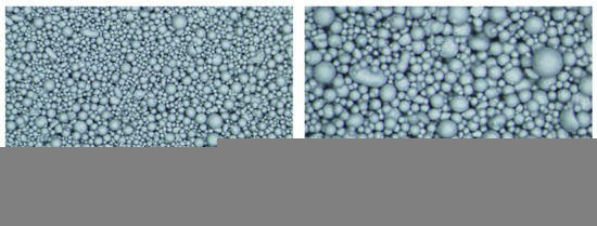
Figure 1.
LOM pictures of a typical spray-dried powder used presently. Magnification ×3.2 to the left and ×6.3 to the right.
WC is a very hard material but is on its own much too brittle for any type of practically relevant tooling application. However, combined with a binder phase of Co, a unique combination of hardness and toughness is achieved, which is beneficial for any tooling application. The carbide powder also contains some alloys that, depending on the application, can be altered and used to control certain mechanical and other parameters during processing. For instance, chromium carbide is used to deaccelerate grain growth during sintering.
To achieve a variation of the properties of the compacted RTP powder, the PEG amount and type is varied, according to Table 1. It should be noted that the pressing agent (PEG) is added to hold the compacted green body together before sintering. It also increases the flowability of the powder, which is necessary for automatic filling of the pressing tool die. After pressing, the powder blank is sintered with liquid phase sintering. During this process, the pressing agent is decomposed, leaving only the cemented carbide in the finished insert. The amount of PEG is within the range used in production. In previous studies [29,30], tests with even higher amounts were successfully performed.
The two types of experiments performed during the investigation are standard uniaxial pressing three-point bending and are described in detail below. Additional and relevant information on the different features of the tests can also be found elsewhere in [29,30].
2.2. Experimental Design
Two parameters were varied to achieve the test points, PEG amount (1.0, 1.5, and 2.0 wt.%) and PEG hardness (soft, medium, and hard). Five test points were selected according to a reduced experimental design scheme, also called a 2k-factorial design with an additional center point. A 2k-factorial design means that two levels are investigated for each parameter. For this experiment, the center point allows for an additional test level, see Table 1.
2.3. Spring Back Measurement
The elastic spring back was measured in a standard uniaxial production pressing machine, using a SNUN pressing tool (square). The width (w1 and w2) is 15 mm, see schematic in Figure 2a. It was compacted double-sided and then slowly unloaded single-sided from the top with an unloading velocity of 0.05 mm/s. The same turning position of 7.4 mm was used for all powders (it should be stated that the flexibility of the pressing tool was not considered). The amount of powder filled into the die was chosen in order to keep the sintered volume constant. The machine and tool elasticity are compensated in the presented results. To retrieve the tool elasticity, the punches were pushed against each other, simultaneously recording the force and position, showing a behavior that can be described as very close to linear.
The force on the upper punch during unloading is measured, compensated and compared between the investigated powders. It should be noted that this is for the comparison of the elastic behavior between different types of powders rather than a measurement of actual elastic data, which of course depends on the geometry.
2.4. Three-Point Bending Test
The green strength was measured using three-point bending tests with a setup based on the standard ISO-3995 [31] for the determination of the green strength in metallic powder compacts. The green strength is defined as the mechanical strength (failure stress) of a cold pressed powder compact. The specimen used was a cuboid with a length (l) of 30 mm, a width (w) of 12.7 mm, compacted to a thickness (t) of 6.0 mm, as seen in Figure 2b.
The tensile tester used was from a ZwickRoell with a load cell up to 100 N and with tolerance of ±0.2 N [32]. The lower fixture has two cylindrical supports mounted 25 mm apart from each other. The upper fixture consists of a cylinder, centered between the two supports. The cylinder is attached to a flexible head and in turn the load cell.
Before testing, the reliability of the method was thoroughly investigated. A range of different test velocities and settings were tested and accordingly statistically evaluated. The aim here was to achieve a higher accuracy of the results, better repeatability, and also a test duration of around ten seconds, according to the ISO standard. Five to seven specimens of each powder were tested. The test speed was 0.1 mm/min with a preload of 1 N and velocity until the preload was achieved at 2 mm/min. Once the preload was reached, a hold time of 2 s was then added to further improve the stability of the measurement. Adding a hold time to the method helped to ensure that the upper fixture, which is attached to a flexible head, would have the possibility to adjust and align with the specimen prior to the start of the test. During the evaluation of the method, it was found that if the upper fixture did not align properly horizontally with the specimen, the recorded test data showed low repeatability and a significant variation. The problem causing this variation was due to the fact that the specimens were brittle, and the force needed for the flexible head to align was too large compared to the force needed to break (fracture) the specimen. Therefore, if the flexible head did not align with the sample, it was accordingly repositioned.

Figure 2.
Experimental setups. (a) Schematic of the SNUN geometry used for the measurement of spring back. The form of the specimen is a square with w1 = w2 = 15 mm. (b) Schematic of the geometry used for three-point bending tests. It is compacted from the top and bottom. The specimen, a cuboid, has a length (l) of 30 mm, a width (w) of 12.7 mm, compacted to a thickness (t) of 6.0 mm. (c) Test setup of the three-point bending test. The tensile tester is from ZwickRoell [32] with a load cell up to 100 N and with a tolerance of ±0.2 N. The lower fixture has two cylindrical supports mounted 25 mm apart. The upper fixture consists of a cylinder, centered between the two supports. The cylinder is attached to a flexible head and in turn, the load cell.

Once the hold time was finished, the test was allowed to run until fracture occurred and the force at fracture was recorded (the corresponding strength was determined as outlined just below). The green strength (GS) was calculated, based on standard Bernoulli beam theory, according to the following expression:
GS = 3 PL/(2 wt2)
In Equation (1), P is the break force (force at failure), L is the distance between the supports, w the width and t the thickness of the specimen. It should be emphasized that since Bernoulli beam theory is relied upon, large deformation (strain) effects are not accounted for in the evaluation. This is not a major issue here as, due to the brittleness of the material, deformations are small at failure.
3. Result and Discussion
In this section, the experimental results are evaluated in the context of PEG influence on the elastic and plastic mechanical behavior of the hard metal powder compacts. It is then assumed that the unloading process is essentially completely elastic (no reverse plasticity), while at fracture process, plastic effects will intervene. Accordingly, the influence on the elastic behavior is clarified when analyzing the elastic spring back measured in the uniaxial pressing machine. The influence on the plastic behavior is clarified when analyzing the green strength measured during the three-point bending tests (evaluated according Equation (1)). Results pertinent to the elastic behavior are shown in Figure 3, Figure 4 and Figure 5, while results pertinent to the plastic behavior are shown in Figure 6. The error bars show a significant difference between the test powders, even though the breaking force is low.
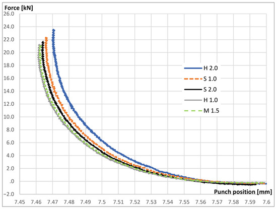
Figure 3.
Punch force during single-sided unloading, as a function of punch position.
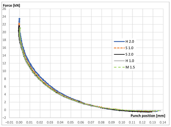
Figure 4.
Unloading punch force, as a function of punch position, where the turning position of the punch is set to zero.
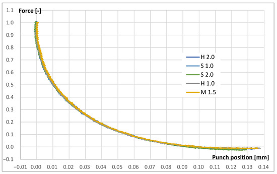
Figure 5.
Normalized unloading punch force, as a function of punch position, where the turning position of the punch is set to zero. The punch force is normalized with the maximum force value pertinent to each test.
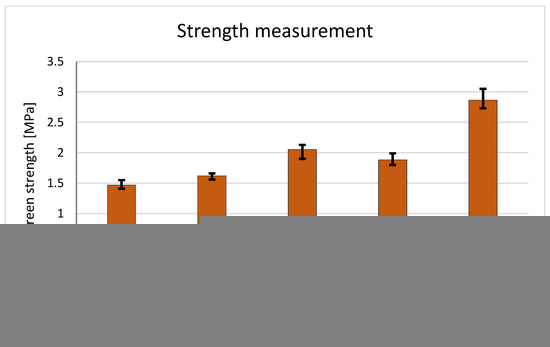
Figure 6.
Results from the three-point bending test. The green strength of the materials is shown. The experimental results are evaluated using Equation (1), relying upon Bernoulli beam theory, neglecting the effect from large deformations (strains).
For clarity, it should be stated once again that the risk for initiation of cracks is influenced by both the elastic and plastic behavior after compaction. In order to determine how the pressing agent will affect the cracking of the green body, it is important to understand its effect on these two features. This is the aim of the present investigation.
3.1. Elastic Behavior
The result from the elastic spring back can be seen in Figure 3, Figure 4 and Figure 5. In Figure 3, the force on the upper punch during slow unloading, as a function of the punch position, is shown. It is observed that the elastic behavior in the pressing direction for this specific geometry is highly nonlinear and it is believed that this is also valid in general for powder compacts of this material (discussed above). Since the pressing tool itself has a small flexibility that has been compensated for, the turning position differs for the different testing powders. In Figure 4, the turning position of the punch is set to zero and evidently, the result then shows similar behavior for the different granulated powders.
The sintered volume is kept constant in this test, leading to a higher powder volume and a higher pressing force when the powders with more PEG are tested. This effect can be seen in both Figure 3 and Figure 4. In Figure 5, the pressing force is normalized with its maximum force. The results clearly show that the elastic behavior, i.e., the spring back, is almost identical for the different test powders. As previously mentioned, the comparison between the powders and the specific load is valid for this geometry, but the behavior is of course similar for other pressing tool shapes.
Indeed, the results in Figure 5 indicate that this relation can, when forces are properly normalized, be easily expressed as a closed-form solution. This would be advantageous when evaluating the influence from different quantities.
3.2. Plastic Behavior
Figure 6 shows the result from the three-point bending test as described above. The maximum force before rupture is recalculated to a stress based on the standard Bernoulli beam theory as stated in Equation (1), using the average from four to six measurements. It can be seen that green strength increases with an increased amount of pressing agent PEG, as well as increased hardness (mole weight of the PEG). The maximum and minimum values are also presented in Figure 6 and show good repeatability.
It is interesting to note from the results that the combination of the increased amount of pressing agent PEG and hardness leads to even stronger green bodies. Accordingly, there is a combination or synergy effect. In Figure 7, the break surface can be seen. Deformed granules are clearly visible.
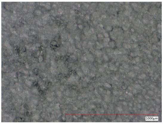
Figure 7.
Typical break surface from a three-point bending test. Deformed granules are clearly visible.
However, it is also evident that the kind and amount of pressing agent influences the plastic behavior of the green body. It is also clear from the results that this can be measured with a three-point bending test where the green specimen is pre-compacted in a pressing machine.
The fact that PEG influences plastic deformation has to be accounted for in any type of plasticity model aiming to describe the powder compaction process. Further experimental efforts are then of course needed to determine PEG effects in a detailed manner for both the hydrostatic and deviatoric components of the plastic deformation.
3.3. Discussion
The risk for the initiation of cracks is influenced by the elastic and plastic behavior after compaction. The spring back after compaction and the green strength defines to a large extent the risk for cracks, and here, we investigated how this is influenced by the pressing agent PEG.
As already mentioned above, knowledge of the influence from the pressing agent on the elastic and plastic behavior of the powder compact is indeed necessary for the macromechanical (constitutive) and micromechanical modeling of the material. The results above provide a solid foundation when performing such tasks.
Based on the experimental outcome reported above, it can be concluded that the plastic behavior rather than the elastic behavior will be influenced by the pressing agent. In an industrial situation, this could be an interesting finding when minimizing the risks for cracks during pressing as well as understanding the unloading behavior. In addition, it can also be concluded that a three-point bending test can be used as a good indicator when examining RTP powders in the context of pressing properties and assessing the risk for crack formation after compaction.
4. Conclusions
During unloading, pressed hard metal powder compacts expand (spring back), possibly leading to unwarranted crack initiation in the green body. In the present study, the elastic spring back and the green strength are analyzed using experimental methods for different types and amounts of pressing agent PEG (polyethylene glycol). In summary, the most important conclusions obtained from this investigation are:
- For spray-dried powders, a three-point bending test is sufficient to test the risk initiation of cracks for different powders;
- The pressing agent (PEG) does not influence the elastic behavior of the powder compact;
- The pressing agent (PEG) influences the plastic behavior of the powder compact.
It should be noted that the present results are valid for the PEG amounts (1 vol%, 1.5 vol% and 2 vol%) and types investigated here as pertinent to an industrial situation. The types are distinguished by different hardness. For future work, it could be interesting to also examine the different types of pressing agents and their influence.
Author Contributions
Conceptualization, H.S., M.B., D.F. and P.-L.L.; methodology, H.S.; formal analysis, H.S. and P.-L.L.; investigation, H.S. and P.-L.L., M.B. and D.F.; resources, H.S.; writing—original draft preparation, M.B., D.F. and P.-L.L.; project administration, P.-L.L.; funding acquisition, H.S. and P.-L.L. All authors have read and agreed to the published version of the manuscript.
Funding
This research received no external funding.
Data Availability Statement
Not applicable.
Conflicts of Interest
No conflict of interest.
References
- Kvashnin, A.G.; Tantardini, C.; Hayk, A.; Zakaryan, H.A.; Kvashnina, Y.A.; Oganov, A.R. Computational Search for New W–Mo–B Compounds. Chem. Mater. 2020, 32, 7028–7035. [Google Scholar] [CrossRef]
- Tantardini, C.; Benassi, E. Crystal structure resolution of an insulator due to the cooperative Jahn–Teller effect through Bader’s theory: The challenging case of cobaltite oxide Y114. R. Soc. Chem. 2018, 47, 5483–5491. [Google Scholar] [CrossRef]
- Bolatova, Z.; German, D.; Pakrieva, E.; Pak, A.; Larionov, K.; Carabineiro, S.A.C.; Bogdanchikova, N.; Kolobova, E.; Pestryakov, A. Ni, Co and Ni-Co-Modified Tungsten Carbides Obtained by an Electric Arc Method as Dry Reforming Catalysts. Catalysts 2022, 12, 1631. [Google Scholar] [CrossRef]
- Pak, A.Y.; Shanenkov, I.I.; Mamontov, G.Y.; Kokorina, A.I. Vacuumless synthesis of tungsten carbide in a self-shielding atmospheric plasma of DC arc discharge. Int. J. Refract. Met. Hard Mater. 2020, 93, 105343. [Google Scholar] [CrossRef]
- Räsänen, S. Studies on Stability and Oxygen and Water Absorption Characteristics of YBaCo4O7 + Delta and LiFePO4. Doctoral Dissertations, Aalto University Publication Series. Aalto University, Espoo, Finland, 2012; p. 128. [Google Scholar]
- Pendse, R.; Stringer, J. The influence of alloy microstructure on the oxide peg morphologies in a Co-10% Cr-11%Al alloy with and without reactive element additions. Oxid. Met. 1985, 23, 1–16. [Google Scholar] [CrossRef]
- Joo, Y.; Ahmed, M.S.; Han, H.S.; Jeon, S. Preparation of electrochemically reduced graphene oxide-based silver-cobalt alloy nanocatalysts for efficient oxygen reduction reaction. Int. J. Hydrogen Energy 2017, 42, 21751–21761. [Google Scholar] [CrossRef]
- Chuankrerkkul, N.; Davies, H.A.; Messer, P.F. Application of PEG/PMMA Binder for Powder Injection Moulding of Hardmetals. Mater. Sci. Forum 2007, 561–565, 953–956. [Google Scholar]
- Chorney, J.; Downey, J.; Sudhakar, K.V.; Ashbaugh, M. Thermal Analysis of Potential High Entropy Alloy Binder Alternatives for Tungsten Carbide. In 12th International Symposium on High-Temperature Metallurgical Processing; The Minerals, Metals & Materials Series; Trans Tech Publications Ltd.: Wollerau, Switzerland, 2022. [Google Scholar]
- Michrafy, A.; Kadiri, M.S.; Dodds, J.A. wall friction and its effects on the densitydistribution in the compaction of pharmaceutical excipients. Trans. IChemE 2003, 81, 946–952. [Google Scholar] [CrossRef]
- Korachkin, D.; Gethin, D.T.; Lewis, R.W.; Tweed, J.H. Friction measurement and lubrication in unloading and ejection stages in powder pressing cycle. Powder Metall. 2008, 51, 14–30. [Google Scholar] [CrossRef]
- Aydin, İ.; Briscoe, B.J.; Şanlitürk, K.Y. Density distributions during the compaction of alumina powders: A comparison of a computational prediction with experiment. Comput. Mater. Sci. 1994, 3, 55–68. [Google Scholar] [CrossRef]
- Macleod, H.M. The determination of density distribution in ceramic compacts using autoradiography. Powder Technol. 1977, 16, 107–122. [Google Scholar] [CrossRef]
- Staf, H.; Andersson, D.C.; Lindskog, P.; Larsson, P.-L. On the Influence of Material Parameters in a Complex Material Model for Powder Compaction. J. Mater. Eng. Perform. 2016, 25, 4408–4415. [Google Scholar] [CrossRef]
- Andersson, D.C.; Lindskog, P.; Staf, H.; Larsson, P.-L. On material parameter sensitivity at the production of hard metal components by powder compaction. J. Mater. Eng. Perform. 2014, 23, 2199–2208. [Google Scholar] [CrossRef]
- Martin, C.L. Elasticity, fracture and yielding of cold compacted metal powders. J. Mech. Phys. Solids 2004, 52, 1691–1717. [Google Scholar] [CrossRef]
- Jonsén, P.; Häggblad, H.-Å. Modelling and numerical investigation of the residual stress state in a green metal powder body. Powder Technol. 2005, 155, 196–208. [Google Scholar] [CrossRef]
- Coube, O.; Riedel, H. Numerical simulation of metal powder die compaction with special consideration of cracking. Powder Metall. 2000, 43, 123–131. [Google Scholar] [CrossRef]
- Larsson, P.-L. On the Mechanical Behavior at Sharp Indentation of Materials with Compressive Residual Stresses. Mater. Des. 2011, 32, 1427–1434. [Google Scholar] [CrossRef]
- Hehn, L.; Zheng, C.; Mecholsky, J.J.; Hubbard, C.R. Measurement of residual stresses in Al2O3/Ni laminated composites using an X-ray diffraction technique. J. Mater. Sci. 1995, 30, 1277. [Google Scholar] [CrossRef]
- Rendler, N.J.; Vigness, I. Hole-drilling strain-gauge method of measuring residual stresses. Exp. Mech. 1973, 13, 45. [Google Scholar]
- Flavenot, J.F.; Niku Lari, A. La mesure des contraintes résiduelles. Méthode de la flèche. Méthode de la source des contraintes. Application au grenaillage de précontrainte et à d’autres traitements superficiels. Mem. Techn. Cetim. 1977, 31, 6–42. [Google Scholar]
- Olsson, E.; Larsson, P.-L. Micromechanical investigation of the fracture behavior of powder materials. Powder Technol. 2015, 286, 288–302. [Google Scholar] [CrossRef]
- Heyliger, P.R.; McMeeking, R.M. Cold plastic compaction of powders by a network model. J. Mech. Phys. Solids 2001, 49, 2031–2054. [Google Scholar] [CrossRef]
- Redanz, P.; Fleck, N.A. The compaction of a random distribution of metal cylinders by the discrete element method. Acta Mater. 2001, 49, 4325–4335. [Google Scholar] [CrossRef]
- Martin, C.L.; Bouvard, D.; Shima, S. Study of the particle rearrangement during powder compaction by the discrete element method. J. Mech. Phys. Solids 2003, 51, 667–693. [Google Scholar] [CrossRef]
- Hertz, H. Über die Berührung Fester Elastischer Körper. J. Reine Angew. Math. 1881, 92, 156–171. [Google Scholar]
- Olsson, E.; Larsson, P.-L. On the Effect of Particle Size Distribution in Cold Powder Compaction. J. Appl. Mech. 2012, 79, 51017–51018. [Google Scholar] [CrossRef]
- Salmi, K.; Staf, H.; Larsson, P.-L. On the relation between pressing energy and green strength at compaction of hard metal powders. J. Mater. Eng. Perform. 2021, 30, 2545–2551. [Google Scholar] [CrossRef]
- Salmi, K.; Könberg, E.; Staf, H.; Larsson, P.-L. Correlation between granule strength and green strength at compaction of cemented carbide powder materials. J. Mater. Eng. Perform. 2021, 30, 9078–9083. [Google Scholar] [CrossRef]
- ISO Standard No 3995; Metallic Powders-Determination of Green Strength by Transverse Rupture of Rectangular Compacts. International Organization for Standardization: Geneva, Switzerland, 1977.
- ZwickRoell. Product Information—Xforce Hp Load Cell. Available online: https://www.zwickroell.com/fileadmin/content/Files/SharePoint/user_upload/PI_EN/03_676_Xforce_HP_load_cell_PI_EN.pdf (accessed on 27 May 2022).


Disclaimer/Publisher’s Note: The statements, opinions and data contained in all publications are solely those of the individual author(s) and contributor(s) and not of MDPI and/or the editor(s). MDPI and/or the editor(s) disclaim responsibility for any injury to people or property resulting from any ideas, methods, instructions or products referred to in the content. |
© 2023 by the authors. Licensee MDPI, Basel, Switzerland. This article is an open access article distributed under the terms and conditions of the Creative Commons Attribution (CC BY) license (https://creativecommons.org/licenses/by/4.0/).