1. Introduction
Magnetic garnets represent an evergreen family of magnetic materials. Some fifty years ago, Professor C. Kittel was reputed to have said that yttrium iron garnet (YIG) is the fruit fly of magnetic materials [
1]. The magnetic garnets, in general, have certainly lived up to that reputation as they have been the source of materials for the investigation of a variety of fundamental magnetic phenomena, including ferrimagnetism, domain physics, statics and dynamics of domain walls, magnetic excitations and magnetic spin dynamics. Many of these studies have been possible because of the ease of “engineering” a wide variety of magnetic properties into the garnet structure by substituting a variety of ions of various amounts at the three different cation symmetry sites.
Stimulated by the potential applications, the magnetic, optical, electrical and structural properties of the magnetic garnets have been extensively investigated. It is now tempting but dangerous to say that the basic physical properties of the substituted magnetic garnets are adequately described and understood.
In spite of the permanent and not decreasing interest in magnetic garnets, there is very scanty knowledge about magnetization reversal phenomena in the iron garnet films with mixed magnetic anisotropy. Nevertheless, one of the most important magnetic parameters, coercivity, has not been studied intensively enough recently, but this parameter plays an important, key role in all magnetic applications. The purpose of the present paper is to summarize the formerly achieved results in the area of the magnetic garnet’s coercivity, also calling attention to the special position of this parameter and to initialize new research work in the case of the presently applied magnetic garnets. Results discussed here were achieved in epitaxially grown magnetic garnets, but we believe that important information can be transferred to the area of newly developed—other than LPE grown-materials.
Last but not least, it is important to emphasize another aspect, due to their very high quality, simple magnetic domain structure and simple magnetization process, magnetic garnet films with large uniaxial anisotropy, grown by LPE technique on non-magnetic substrates represent an excellent model material for investigating magnetization processes. The permanent interest in magnetic garnets is demonstrated by the many recent review papers in this area.
2. Magnetic Garnets
Yttrium iron garnet is a ferrimagnetic material. Menzer found the garnet structure in 1928 in naturally occurring silicates [
2]. The general formula of garnets is A
3Fe
5O
12. Here A can be some rare-earth elements, like Y, Tm, Er, Bi, Gd, Yb, Er, Tb, Ho, Dy, Eu, Sm. A cubic frame is formed by the cations in this crystallographic structure, where cations are placed in the center of an oxygen polyhedron (octahedron, dodecahedron or tetrahedron). All A
3+ ions take the dodecahedral (or
c) sites, and Fe
3+ ions take either octahedral (
a) or tetrahedral (
d) sites in a 2:3 ratio [
3,
4].
The Curie temperature (
TC) of magnetic garnets is significantly larger than the room temperature.
TC is typically in the range of 400–500 K temperature. This ferrimagnetic order primarily originates from super-exchange interactions between the Fe
3+ (
a-site) ions and the Fe
3+ (
d-site) ions [
5].
A3+ ions can antiferromagnetically couple also with Fe3+ ions if they are rare-earth elements with unfilled 4f-shells. In many aspects, magnetic garnets have much better characteristics compared with other magnetic insulators or magnetic metals, very suitable for spintronic applications. The first “renaissance” of yttrium-iron-garnet (YIG) films was in the seventies of the last century when the Czochralski growth technology was developed for the purpose of producing high-quality films for bubble memory application.
Some papers have been published recently about the magnetic behavior of garnets. The magnetic properties of Y
3−2xCa
2xFe
5−xV
xO
12 (0 ≤ x ≤ 1) garnet films were studied in [
6]. Another research aimed to investigate the magnetic and structural properties of YIG by Ni-doped using the self-combustion method [
7]. The results in the area of the LPE magnetic garnet films and their applications are summarized in [
8]. Magnetism and site occupancy were investigated in epitaxial Y-rich yttrium iron garnet films [
9], while magnetic and crystallographic properties of rare-earth substituted yttrium-iron garnet were studied in [
10]. Ferrimagnetic materials comprise rare earth (RE) and transition metal (TM) compounds, wherein the spins of two inequivalent sublattices are coupled antiferromagnetically [
11,
12,
13,
14,
15]. Because of the different Landé g-factors of RE and TM elements, ferrimagnets exhibit compensation temperatures of magnetization and angular momentum, at which the magnetizations of the RE and TM sublattices have the same magnitude but opposite directions. Consequently, the net magnetization (angular momentum) is compensated. The compensation temperature was studied both experimentally and theoretically in [
16]. This compensation point can be observed in garnets and rare-earth–transition-metal alloys. For instance, the gadolinium-iron garnet system has a compensation point in a temperature region of about 300 K. Recently it has been experienced that both the compensation temperature and the Curie temperature can be significantly and linearly enhanced in epitaxial rare earth iron garnet films [
17].
However, in the case of YIG films, which are the subject of this review paper, there is no compensation point, as can be seen directly in
Figure 1, where the typical temperature dependence of the saturation magnetization is shown. Measurement was performed on a 5.3 µm thick epitaxially grown magnetic garnet film with the nominal composition (YSmCa)
3(FeGe)
5O
12.
Magnetic garnet films, produced by LPE (liquid phase epitaxy) technology, are among the perfect single crystalline materials because their growth and the control of the magnetic properties by choosing the best chemical composition are very well-established processes. This is the reason why these films play a very important role in the investigation of the basic magnetization behavior. The large growth-induced uniaxial anisotropy keeps normal the magnetization of the domains and the 180° domain walls to the sample surface. As a consequence, the domain structure seems to be usually very simple, a characteristic maze-like or stripe domain structure. However, in fact, they are not simple at all because the stripe domains are the result of the competition between anisotropy, exchange and magnetostatic interactions in the system, leading to quasi-2D magnetic configurations which can hold topological textures and a lot of interesting physics can be performed with them.
Films are transparent; consequently, the structure of magnetic domains can be observed in any common polarizing microscope by using the Faraday effect. It means that a lot of information about the correlation between domain structure and magnetization process can be obtained by simultaneous measurement of the samples’ magnetization and domain structure visual observation. A typical stripe domain structure can be seen in
Figure 2.
3. Application Possibilities of Different Types of Garnets
The flexibility of ion substitution has led to promising applications of the magnetic garnet materials in microwave devices based on magnetostatic waves propagation [
18], energy-independent information storage (bubble memory devices) [
19,
20], vertical Bloch line memory [
21,
22], a wide range of magneto-optic devices, i.e., shutters, modulators, deflectors, rotators [
23,
24,
25,
26,
27]. As it can be seen from the above arguments, magnetic garnets still are among the most intensively studied magnetic dielectrics, and the last decade of the former century revealed many promising applications in sensors for epitaxial iron garnets having easy plane type magnetic anisotropy, for example, a magneto-optic visualization of the spatial distribution of magnetic field [
28], for the non-destructive testing of high-temperature superconductors, eddy current imaging of defects in plated conducting materials, electric current topography in ICs, inductive and magneto-optical magnetic field sensors for different applications [
29].
Several garnets with substitutional atoms have been found to have degraded magnetic and optical properties. This is caused by the sample property changes, like crystallinity, shape, size and different impurities [
30,
31]. Due to their intriguing quantum phenomena (hybridized magnon–phonon excitation), recent magnetic garnets are also considered key materials for communication systems and quantum computing [
32].
In spintronic applications nowadays, magnetic garnet films have started to take the place of conducting ferromagnetic materials. Their outstanding properties, namely low energy consumption, high integration density and room temperature fast operation speed, make garnet films suitable for the next generation applications in spintronic and photonic devices. The disadvantages of eddy currents, which can cause loss of information in some applications, are eliminated by the insulating features of the garnets. The low Gilbert damping makes possible numerous applications in spintronics. These applications require perpendicular magnetic anisotropy (PMA), but there are only a few PMA-type garnets, for instance, terbium and samarium garnets. In Ref. [
33], new epitaxial magnetic iron garnet film/substrate pairs have been predicted with stable PMA. It has been shown those conditions where new garnet types may possess PMA. These garnet films with tunable saturation moment and field could improve compensated magnonic thin films and spin-orbit torque memory devices.
Rare-earth-doped ferromagnets produce an enhancement of the Gilbert damping parameter, which is due to the slow relaxation of the 4
f-electron spins of rare-earth atoms. The exchange coupling between a thin ferromagnetic garnet film and a rare-earth thin film having nanometer size has been investigated only to a limited extent. In [
34], yttrium iron garnet (YIG)/dysprosium (Dy) heterojunctions were fabricated, and microstructural, static and dynamic magnetic properties were studied. High modulations of the magnetic anisotropy field, magneto-optic Kerr rotation angle and Gilbert damping parameter were found in single-crystalline thin YIG films capped by rare-earth Dy nano-films.
Moreover, the present other advances in magnetic garnet thin film development for applications in photonics and spintronics are discussed in [
35,
36], and there is a review of the Bi-substituted ferrite garnet magneto-optic materials in the paper [
37]. Dynamic and static magnetic properties of single-crystalline epitaxially grown YIG films on pure GGG (gadolinium gallium garnet), on rare-earth-substituted GGG, and on neodymium gallium garnet (NGG) substrates were investigated in [
38].
The Interest in these materials recently has been related to applications towards thermomagnetic recording made by electron or laser beams. Additionally, new possible areas of application are the control and processing of optical signals, the designing of reconfigurable atom traps and the transport control of the magnetic nanoparticles. High-performance magnetic sensors can be produced with enhanced sensitivity, which are suitable for visualization and detection of localized weak magnetic fields Bi-substituted rare-earth iron garnets can be used as optical isolators, too and also as other magnetooptical (MO) devices because in the visible light region they have large MO effect. Bi-substituted garnets are used as spatial light modulators, waveguide-type isolators, and MO indicators. The bismuth-substituted neodymium iron garnet films, grown on glass and gallium gadolinium garnet substrates, were studied, and their electro- and magnetostriction mechanisms and temperature behavior were determined in. Bi, Pr- and Bi, Sc-substituted lutetium iron garnet films with planar magnetization for the purpose of magneto-optic visualization were grown and characterized [
39].
Also, a novel application can be in non-linear optics, especially for optical data processing. These garnets can be usefully applied in non-destructive testing, too. In the majority of the above-mentioned applications, a well-defined magnetic structure should be realized, in which the transition to the monodomain state is restricted by a high energy barrier.
A new aspect of garnets’ application was suggested in [
40]. In this work, gadolinium iron garnet samples were studied, and the magnetization and coercivity were investigated. At low temperatures, the magnetic coercivity
Hc is determined mainly by the effective anisotropy, but close to the compensation point, a peak can be observed in
Hc as a result of the so-called para process having a maximum value of 95,000 A/m at the T
comp compensation point. Increasing the temperature further, the coercivity decreases and vanishes around temperature 500 K. Interparticle interactions play an important role in the hysteresis behavior of the material.
From the point of view of sensor application, both the development of principles of transducer operation and achieving the best performance of magnetic sensors require the widening and generalization of theoretical concepts on magnetization processes, domain structure formation and evolution under external field influence, magnetic losses and noise properties of epitaxial iron garnets with mixed uniaxial and cubic magnetic anisotropy.
Regular, non-destructive inspection of structural parts of machinery, vehicles, bridges, power plants etc. is crucial in everyday technique. Magnetic methods, among others, coercivity measurements, are very important in nondestructive material evaluation [
41,
42], as reported by Blitz and Jiles. There exists an analogy between material microstructure modification, generated by different effects (for instance, how dislocations move) and magnetic behavior modification due to a magnetizing field. This correlation can be used to characterize the materials when magnetic hysteresis is measured. In a ferromagnetic material, the movement of dislocations and domain walls are both affected by the defects in the material’s microstructure. The close correlation between mechanical and magnetic hardness in ferromagnets is well-known and well-understood, as reported by Kronmüller [
43]. Magnetic methods usually are technically simple, it is not an expensive technique, and these methods can be applied via electrical cables.
4. Magnetic Skyrmions
A new branch of physics should be obviously mentioned, which—in several aspects—shows similarity with the physics and application of magnetic garnets, and it can now find a productive and perspectivious field of applicability. They are magnetic skyrmions, which can be realized in helimagnetic materials. The original concept of skyrmions was proposed in the 1960s by Skyrme to account for the stability of hadrons in particle physics [
44]. Magnetic skyrmions are topologically nontrivial magnetic quasiparticles. They can be characterized by a topological charge. Their stabilization and dynamics of them depend much on their topological properties. In many cases, they are induced by chiral interactions between atomic spins in thin films with broken inversion symmetry. Skyrmions are usually very small, having diameters in the range of nanometers. They behave as particles that can be moved, created and annihilated. This feature makes them suitable for ‘abacus’-type applications in information storage and logic technologies. The field of magnetic skyrmions has been intensively investigated across a wide range of topics in the last decade. However, recently there has been a renewed interest in the topological properties of magnetization textures, according to the recent developments of the quantum Hall effect theory and the discovery of topological insulators. Many publications can be found on this subject, see, e.g., [
45,
46]. A very recent review has been published about magnetic skyrmions; see [
47].
Topologically, skyrmions are equivalent to magnetic bubbles in magnetic garnet films. In papers [
48,
49,
50], the question is analyzed, what is the difference between magnetic skyrmions and magnetic bubbles, even if they seem to carry the same topological winding number (or topological charge)? It was found that such difference exists, facilitated by a different role played by the magnetization vector’s in-plane phase.
5. Coercivity
Coercivity, coercive force, and coercive field are one of the most commonly used parameters if a ferro/ferrimagnetic material should be characterized. The coercive field is usually determined as the half-width of the major hysteresis loop. This quantity is in close correlation with the hysteresis losses of the material. The technical coercivity, Hct, is equal to the external magnetic field necessary to decrease the total magnetic moment of the sample to zero. The sample should be previously saturated magnetically. Although this is an important parameter in practical applications, it is not easy to find its direct correlation with the individual micromagnetic processes which take place during the magnetization reversal. Furthermore, it depends on the value of the maximal external magnetic field. Apart from the closed magnetic circuits (e.g., measured on ring shape samples), reaching the total magnetic saturation is very difficult or impossible. In principle, it is, of course, true that if the coercivity is increasing, this means that the sample (due to geometry and/or properties) has not been properly saturated, and regions with “memory” have acted during reversal as easier nucleation points. However, in practice, it is very difficult to reach the full saturation. It is many times justified empirical experience that coercivity really depends on the applied maximal field, even in the case when we are already on the horizontal part of the magnetization curve, and the magnetic moment of the sample is not increased anymore. In the great majority of existing experimental systems, it was not possible to reach the whole saturation.
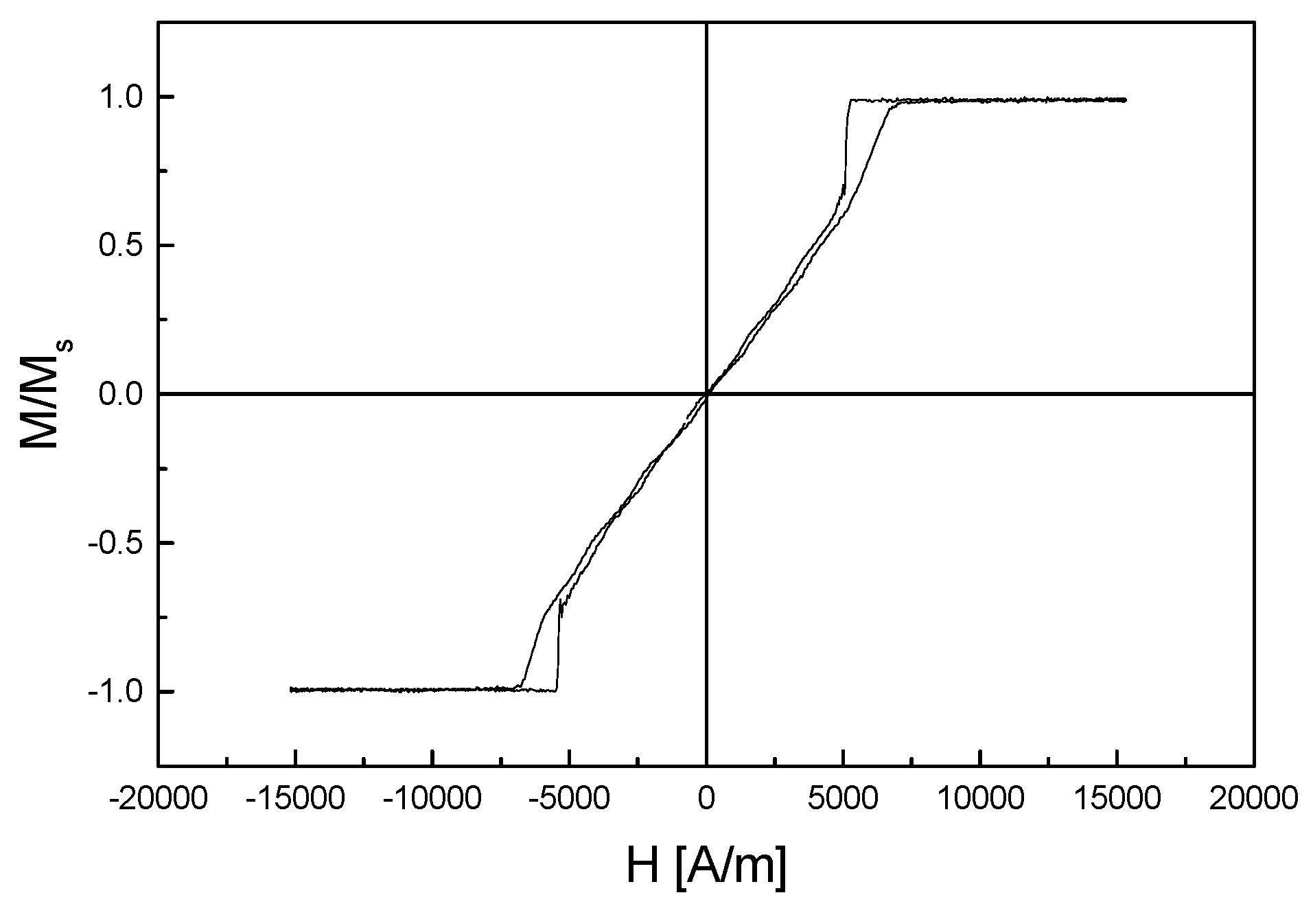
As an illustration and justification of the above statement, a full (major) hysteresis loop of a garnet film is shown in
Figure 3. It was measured magneto-optically on a 5.1 µm thick epitaxially grown magnetic garnet film with the nominal composition (ySmCa)
3(FeGe)
5O
12. A typical feature of this hysteresis curve is a sudden jump during the decrease of the field after the magnetic saturation of the sample, which is caused by domain wall nucleation. The hysteresis loop suggests that the sample is saturated if the external magnetic field (applied normally to the film surface) is larger than 7500 A/m. However, if the
Hc coercive field is determined from the widths of minor hysteresis loops with increasing
Hmax field values, it is seen that no “saturation” of
Hc can be reached, at least in the measured range of the applied external magnetic field. This phenomenon is shown in
Figure 4.
Evidently, it is not stated that this phenomenon exists for all magnetic materials in any case. However, it is a general experience of the investigated magnetic garnet films.
There is always some interaction between magnetic domain walls and material imperfections. This is true even for very soft magnetic materials [
51,
52]. It was shown in [
53] that a characteristic parameter of coercivity, the so-called domain wall coercive (or domain wall pinning) field,
Hcw, could be evaluated from reproducible and well-defined minor hysteresis loops. In this case, domain walls are the probes of the defects, and the measured domain-wall coercive field contains information on the distribution and properties of the defects [
54].
The physical properties of magnetic materials determine the nature of the coercivity and the resulting magnetic behavior. To characterize the pinning of domain walls at the defects, Aharoni [
55] applied the specific Ritz model for the wall structure using a modification of Hilzinger’s theory [
56]. Della Torre [
57] reviewed the problems in modeling the coercivity of soft magnetic materials. Numerous theories (a review is given in Ref. [
51] have attempted to calculate the coercive field from an assumed distribution of the material defects and from material parameters.
Hcw is the minimum mean external magnetic field, which is necessary to move the domain walls
irreversibly from their original position.
Hcw is the half-width of minor coercive loops (CL). These loops are measured in the
H external magnetic field, which is applied parallel to the easy axis of the sample. The sample should be demagnetized carefully before the measurement. The coercive force, determined from the major hysteresis loop, was found usually significantly larger than the domain wall coercive field [
58]. This
Hcw, determined from the minor loops, is the true characteristic of domain-wall defect interaction. It characterizes the behavior of domain walls: the local jumps of short domain wall segments between imperfections [
59] are averaged.
The coercivity Is correlated with the basic magnetic properties of the material, such as anisotropy, exchange constant and magnetization. This is the reason why Hcw is considered one of the most important properties in applied magnetism. On the other side, however, it also characterizes the materials’ structural nonuniformities through their interaction with the domain walls and the magnetization vector via the distance dependence of the domain wall energy dEw/dx: Hcw = (l/MS)(dEw/dx)max. The domain walls are the probes of the material imperfections (defects), and the measured domain wall pinning field value contains information on the defects’ distribution and quality. Over the last decades, a large amount of effort was devoted to revealing the origin and character of coercivity and to understanding the mechanism of domain wall restoring forces.
If an
H external field is applied, starting from the demagnetized stripe domain structure, the magnetic moment of the sample is modified only by domain wall motion. The domain wall motion starts only if |
H| >
Hcp. Domain wall coercive loops (DWCL) describe the start of the wall motion, and the slope of their branches characterizes the susceptibility (see, e.g., [
52]).
The coercivity is sensitive to the structure, but in epitaxial magnetic garnet films, due to the very low density of dislocations and surface defects, the typical value of the coercivity,
Hc, is of the order of 10 A/m. Statistical fluctuations of material parameters, localized surface defects and dislocations give an almost negligible contribution to
Hc. However, in those applications where only a few domain boundaries exist (e.g., in spatial field sensors), domain structure with controlled coercivity should be present. The ferrite garnets could be made magnetically “harder” by choosing an appropriate composition of the substrate and the material. In single crystalline epitaxial magnetic garnet films, the tuning of magnetic hysteresis was studied, and the optimization of technological methods was suggested to produce a high-coercivity material [
60]. It was demonstrated as well that high coercivity values and optical absorption were achieved. It was caused by lattice mismatch stress and oxygen vacancies compensating the calcium anions in garnet films containing Ca. A high-coercive garnet film for imaging magnetic recordings was also developed [
61].
6. Measurement of Coercivity
In this section, the measurement methods described were used in our experiments for determining the domain wall coercivity,
Hcw. Usually, the coercivity for the routine characterization of magnetic garnet films is measured on a (demagnetized) stripe domain structure. A low-frequency ac magnetic field is applied—normal to the film surface—with increasing amplitude. The start of the domain wall motion of stripe domains is detected photoelectrically [
62]. This is the most frequently used method—called the domain wall oscillation method—for measurement of the domain wall coercive field in magnetic garnet films. The magneto-optical response of the domain system to an ac magnetic field perpendicular to the film plane is used in this method. The field amplitude corresponds to the motion of domain walls. The extrapolated start of domain wall motion is interpreted as
Hcw.
This method is performed on an optical bench, and the Faraday effect is used to detect the changes in the magnetic state [
63]. Measurement starts from the demagnetized, equilibrium domain structure, which is reached by an ac field demagnetization. The ac measuring field is oriented normally to the sample plane, and its amplitude is increased linearly from zero. The amplitude of the domain wall response is measured by using a lock-in amplifier. From the recorded curves, the average displacement of the domain walls can be determined as a function of the increasing ac magnetic field amplitude. The linear part of the detected plot is extrapolated to the zero domain-wall response. The corresponding field amplitude is denoted as
Hcw. The accuracy of the measurement is about ±10 A/m. The detected curves, together with the way of extrapolation, are shown in
Figure 5. This graph is presented for illustration of the measurement, and because of this, a garnet sample with unusually large coercivity was chosen. In this graph, it is indicated as well that the measurements were performed at different frequencies of the measuring field (20 Hz–1 kHz). The domain wall coercive field, determined from the graphs, is
Hcw = 290 A/m.
Quasistatic CL hysteresis loops are measured in a VSM (vibrating sample magnetometer. The accuracy of the measurement is ±150 A/m for determining the width of loops. The
MS saturation magnetization is also measured by VSM measurements, detecting the saturation hysteresis loops along the easy axis. As an illustration, a set of measured minor loops (at
f = 25 Hz frequency) is shown in
Figure 6, with increasing
Hmax values. Again, this graph is for the illustration of the measurement, and this measurement was performed on another sample than shown in
Figure 5. Moreover, for better visibility of curves, a measurement is shown, which was performed at
T = 71 K temperature after a computer elimination of the paramagnetic contribution of the substrate. It is seen that the coercive field is constant
Hc = 920 A/m, regardless of the applied slope of magnetizing field.
It was found—by taking into account the results of numerous measurements—that the
Hcw values, measured by the domain wall oscillation method and by the above-presented quasistatic minor coercive loops, are equal to each other within the error of the experiment [
53].
In the literature, at least three terminologies are used for this parameter: domain wall coercive field, or domain wall oscillating field, Hcw and domain wall pinning field, Hcp. These parameters are totally equivalent to each other, and both of them are used in this review.
7. Magnetic Garnet Films’ Growth Process
The production technology of magnetic garnet films is not the main subject of this review. Nevertheless, it is important to have at least a brief look at how these films are grown.
In general, thin magnetic films, which have nearly perfect crystalline structures, are very good means to study the subtle details of coercivity. This statement is particularly true for thin garnet films, where the uniaxial magnetic anisotropy is in the easy axis, which is normal to the film plane. Due to this property, epitaxial magnetic garnet films are frequently used for investigations. These films are among the most perfect single-crystalline materials. This is because of their growth technology (liquid phase epitaxial, LPE), where the control of their magnetic properties is a very well-developed process [
64,
65]. Inside all domains, the magnetization vector is aligned perpendicular to the film surface, and the domain structure is the so-called well-known stripe or maze-like domain structure. 180° Bloch domain walls exist between neighboring domains. The external magnetic field, which is applied during the magnetization process, is parallel to the magnetization of the domains. The domain walls are always parallel to each other over the range of fields used in the domain wall coercivity measurements.
Epitaxial magnetic garnet films are grown on (111) oriented gadolinium garnet (GGG) substrates by LPE from a traditional PbO-B
2O
3 melt-solution system [
66]. In the majority of cases, the nominal chemical composition of garnet films was either Y
2.03Ca
0.97Fe
4.03, Ge
0.85, Co
0.12O
12, or Y
1.92Sm
0.1Ca
0.98Fe
4.02Ge
0.98O
12. The magnetic parameters can be modified by the proper choice of the growth parameters, which were used during the growth of the samples. The basic magnetic parameters and thickness of the samples are determined by common methods for garnet film characterization. Typical thicknesses of films are between 3 and 5 μm.
Bi and Ga substituted YIG and LuYIG layers have been frequently used in different kinds of magneto-optical applications. Preparation of Bi,Ga: YIG and Bi,Ga: LuYIG layers on GGG substrates grown by conventional isotherm dipping LPE technique using PbO-Bi
2O
3-B
2O
3 system as a solvent is reported in [
67].
8. Origin of Coercivity
It was found that during the growth of Ca-Ge substituted epitaxial SmYIG magnetic garnet films, even minor variations in growth parameters resulted in significant modification of magnetic behavior. These instabilities were not found in the growth of GaSmYIG films. The serious problem was to keep a low coercivity of the films. It was observed that the lattice mismatch, Sm content, melt composition, growth rate, and point defects had an influence on the coercivity [
68,
69,
70,
71,
72,
73,
74].
The relation of coercivity with charge and size differences of the substituting ions and the fact that the magnetic properties of films react in a different way for changes in the growth conditions suggest that the behavior of films is connected with the microstructure and point defects of the garnets [
75].
Two models on the origin of coercivity in some crystals are analyzed in [
76]. The first one, the work of Kersten [
77], suggests that in soft magnetic materials, the coercivity is due to the domain wall energy variation through the crystal. The second one attributes the coercivity to the magnetostatic interactions between domain walls and crystal defects. Introducing the experimentally observed quantities into the models, calculated values for the coercivity can be determined. It turns out that they are very close to the value of the magnetostatic model and very poor to the values of the wall energy variation model.
Ga and Ca-Ge substituted YIG epitaxial garnet films produced for bubble memory applications are thought to be the perfect magnetic materials. However, in spite of their extremely low dislocation and surface defect densities (≤5 cm
2), the coercivity is of the order of 10 A/m depending on compositions and growth conditions. Papers [
51,
78] review the role of various mechanisms in determining the static coercivity of stripe domains in epitaxial garnet crystals. Statistical fluctuations of the material characteristics, dislocations, inclusions and surface defects cannot be fully responsible for the observed coercivity; they are shown to give a negligible contribution to
Hc. The surface roughness and stresses in the transient layer at the epitaxy/substrate interface can cause coercivity from 10 up to 100 A/m. A high density (10
14 to 10
16/cm
3) of micro-defects was deduced from the temperature dependence of
Hc. Transmission electron microscopy (TEM) observations of CaGeSmYIG films revealed a periodically modulated stress field that—via magnetostrictive stresses—can explain the broadening of the FMR line and the measured
Hc. Stresses of 10
7 dyne cm
−2 and Δa/a = 10
−5 with a periodicity of 500 Å cause
Hc~80 A/m, which corresponds to 1–3% Sm or Ca-Ge content periodic fluctuation. The mechanism causes the FMR line to broaden about 15,000–25,000 A/m, i.e., more than the Sm
3+ ions relaxation. This mechanism is attributed to the spinodal decomposition of the garnet.
9. Dependence of Domain Wall Coercivity on Domain Structure and on Magnetic Parameters of the Material
Coercivity, as it was described above, is a rather complex parameter: It depends on material imperfections, which hinder the domain wall motion, but it is very much influenced by the actual magnetic characteristics of the measured material. Furthermore, it is also very much influenced by the actual domain configuration in the sample. In the next subsections, these factors will be analyzed.
9.1. Influence of Samples’ Magnetic Parameters on Coercivity
In this subsection, the correlation between coercivity and material parameters is discussed. Many theories have been devoted to calculating the coercive field from the material parameters and from the assumed distribution of the material defects. For a review of them, see [
51]. Some of these theories adequately matched the experimental observations. A correlation was evaluated between domain wall parameters and the domain wall pinning field. These considerations can be useful for the experimental verification of theories that describe the coercivity based on domain wall parameters.
The effect of mechanical stress caused by lattice distortion was measured on LPE magnetic garnet films [
79]. It was found that mechanical stress had a significant effect on the uniaxial anisotropy and also on the domain wall parameters. The stress dependence of these parameters was used to modify the magnetic behavior of the same sample [
80]. Lattice distortion is due to the different lattice constants of the epitaxial film and of the substrate. Decreasing the thickness of the substrate, the misfit strains in the epitaxial film relax, and the stress-dependent magnetic parameters, like,
Hcw, and the
Ku uniaxial anisotropy constant, can be modified. In the experiment, the substrates were thinned in several steps from the backside by mechanical polishing. In each step of polishing 100 µm thick layer was removed from the substrate. The magnetic parameters were measured again after each step. It was found that
Hcw decreases with decreasing substrate thickness. This is shown in
Figure 7. The effect became more emphasized after reaching a 150 µm substrate thickness. Other parameters of the film are not modified by this procedure.
Measuring the
Hcw and
Ku values, which belong to the same thickness of the substrate, it was possible to find that a linear relationship between
Hcw and
Ku, as shown in
Figure 8. This correlation is characteristic of the given material. The experiment showed—in agreement with the theoretical model—that the domain wall coercive field (measured by the wall oscillation method) highly depends on the uniaxial anisotropy. The slope of this linear function represents the intrinsic coercivity of the material. This result makes a good start for subsequent quantitative evaluations of the relevance of different theoretical models of domain wall coercivity to currently studied materials. However, this result does not mean that coercivity can be calculated by measuring the uniaxial anisotropy of the actual sample.
The relation between the coercivity and magnetic parameters is one side of the coin only. The coercivity also depends very much on the material structure, and samples having very similar magnetic behavior (saturation magnetization, anisotropy, exchange stiffness, etc.) can have different coercive properties. This shows—as already mentioned above, but it cannot be emphasized enough—the rather complex character of coercivity. The importance of the above-demonstrated quantitative correlation between Hcw and Ku is to reveal the type of function between these parameters.
Apart from the basic magnetic parameters of samples, such as uniaxial anisotropy, the properties of domain walls have also a significant influence on the experienced domain wall coercivity [
81]. It is not a surprise because the moving domain walls act as an indicator of material imperfections, and the properties of domain walls determine how they interact with defects. It is possible to determine the correlations between
Hcw and the wall parameters (domain wall energy density and/or domain wall width) [
82,
83]. The temperature dependence of the
σw domain wall energy density and the
δw domain wall width was determined.
The width of 180° Bloch domain walls can be calculated by the well-known expression, where
A is the exchange parameter:
The total energy density of the 180° domain wall in magnetically uniaxial material can be expressed according to Eschenfelder [
84]
The domain wall energy can also be written as (where
l is the characteristic length):
From the above expressions, the exchange parameter
A can be determined in the following form:
By using the values of anisotropy Ku, the saturation magnetization Ms, and characteristic length l, the exchange parameter can be calculated, and its temperature dependence can also be determined if the temperature dependence of Ms, l and Ku is known.
The temperature dependence of
Ku was also determined. In rare-earth-containing materials, the exponential increase of
Ku with decreasing temperature is explained by a single ion model [
85]. The exchange parameter also depends on the temperature; it decreases with increasing temperature up to the Curie temperature. The domain wall energy density also decreases monotonically and exponentially with decreasing temperature. The domain wall thickness increases close to linearly with increasing temperature up to 400 K and then decreases rapidly at temperatures close to the Néel temperature.
The measured temperature dependence of the domain wall coercivity is shown in
Figure 9. The domain wall pinning field changes as expected: the increasing domain wall energy density leads to an increase of
Hcw, while the increasing domain wall width reduces the observed value of
Hcw. Considering the importance of the
Hcw(
T) correlation, an independent subsection is devoted to this problem; it is not discussed here.
The quantitative correlation between
Hcw and the domain wall parameters can also be calculated based on these figures. The dependence of the domain wall pinning on the domain wall parameters can be determined by comparing the measured
Hcw(
T) and calculated
δw(
T) and
σw(
T) curves.
Hcw is shown in
Figure 10 as a function of the domain wall energy density. In this graph, each point represents the corresponding values of
Hcw and
σw at a given temperature. In
Figure 11, a similar relation between
Hcw and
δw is presented.
Hcwe varies as expected: the increasing domain wall energy density leads to an increase of
Hcw, while the increasing domain wall width significantly reduces the observed value of
Hcw. From these figures, a quantitative correlation between
Hcw and the domain wall parameters could also be calculated.
As shown in the figures, a direct correlation was evaluated empirically between
Hcp and the domain wall characteristics. These results support the existing theories, which express the coercivity in terms of the domain wall parameters. They can serve as experimental verification of the theoretical coercivity models. Paul described the mechanism of domain wall pinning [
86]. His calculations revealed that the coercivity is proportional to the domain wall energy. It was assumed in other studies [
87,
88,
89,
90] that domain wall motion takes place through localized pinning sites, which represent energy barriers. These barriers are overcome by thermal energy, and walls break away from the pinning sites under the simultaneous influence of external field and temperature. Gaunt [
91] developed a microscopic, statistical theory where the properties of the pinning sites are taken into account. In this model, the domain wall parameters also play an important role.
9.2. Magnetostatic Designing of Coercivity
Correlation between the coercive properties of a soft magnetic material and the geometry of its domain structure was studied [
92,
93,
94]. The coercive properties of soft magnetic material and the ways of influencing them through engineering of the domain structure geometry are discussed.
Coercivity decreases with increasing gradient, G, which is the effective local domain wall position-restoring magnetic field. The shape of the Hcw(G) dependence is calculated from the mean energy dissipation of the domain wall moving over the particular profile of the domain wall.
In low magnetization thin magnetic garnet films having large uniaxial anisotropy perpendicular to the layer surface, the influence of the
G field gradient on the domain wall coercivity was directly measured [
52]. The domain wall coercive field was found to decrease linearly with the field gradient
G up to a critical value. The experienced
Hcw was equal to zero above this critical value. It means that the observed domain wall moved without any hysteresis loss.
Based on a simple description of the wall-pinning field, calculations resulted in the conclusion that Hcw should be a linear function of the field gradient G, of the form Hcw(G) = Hcw(0) − a, where a is a constant and Hcw(0) is the coercive field of a domain wall, which is free of any position-restoring force.
The dependence of Hcw(G) was calculated using a statistical approach, where the wall-pinning field was described by the Ornstein-Uhlenbeck process. Hcw was predicted proportional with 1/G. The Hcw(G) dependence was determined by numerical and analytical methods. The computed Hcw(G) was found to be close to a hyperbolic decrease. The theoretical predictions and experimental Hcw(G) dependence were compared with each other. Measurements were performed on two different magnetic garnet films having cylindrical bubble domain structures. In the experiments, the field gradient G was changed by modifying the size and density of bubble domains. The comparison between the experiments and the theory led to a quantitative estimate of the typical wavelength of the structural disorder space variations. The result is in agreement with what is expected for the studied materials. The problem addressed in this work is of a general nature, and it is at the heart of the hysteresis mechanisms. The actual origin of the effective restoring force is not important in the determination of coercivity reduction. The magnitude of the G field gradient is only important in determining how much the domain wall pinning is suppressed in comparison with a free domain wall (G = 0) which exhibits the largest value of the DW coercive field Hcw(0). As a consequence, the Hcw(G) dependence is responsible for such rather peculiar, not yet well-described effects, like the Hcw dependence on domain structure subtle features.
By fitting the calculated dependence, Hcw(G), to the empirical data, the values of the Wiener–Lévy correlation lengths were found well comparable to the domain wall width parameters.
Validating the above consideration, a direct correlation between the coercive properties of soft magnetic material and the geometry of its domain structure was studied [
95]. In this work, the coercivity of soft magnetic materials and the ways of influencing them through the engineering of the domain structure geometry are discussed by studying the properties of an epitaxial magnetic garnet film with (YLuSmCs)
3(FeGe)
5O
12 composition.
This subject relates to the coercive properties and geometrical stability of the magnetic structure of ferromagnetic materials. Competition between the local defect coercivity and the global magnetostatic positioning of domain walls makes it possible to use them against each other if it is desirable to diminish (optimize) the coercivity and decrease hysteresis losses.
It is known that the results of measurements of domain wall coercivity can differ from one another if the domain structures of the samples are not the same in each experiment [
96]. The qualitative reason for this observation is clear: the dependence of
Hcw on the position stiffness of the actual domain structure, i.e., the relative freedom of the walls to move from their equilibrium positions [
97]. In the above-mentioned work [
52], quantitative experiments on this dependence were investigated with a single domain wall stiffened at its local position by a variable external magnetic field gradient
Gext. A decreasing linear dependence,
was observed, and besides providing information on the size and distribution of defects in the material [
92], it proved that if the domain wall position in a local artificial magnetostatic energy well is stiffened, the hysteresis of the wall can be substantially lowered. In the above expression,
t is a value that is connected to the defect period of the material.
Experiments were performed on a magnetic garnet film. A regular periodic domain structure of cylindrical domains (so-called bubbles [
98]) was generated before the
Hcw measurement. The scheme of such an array is shown in
Figure 12.
D is the diameter of the bubble domains, and
A is the center-to-center distance of the nearest neighbors.
During the whole experiment,
A was kept constant, and
D was modified by an external uniform bias magnetic field;
H was applied along the easy axis of magnetization (normal to the film’s surface). Positive values of the
H field (directed against the magnetization inside the bubbles) decreased the bubble diameter, whereas negative values of
H made the bubbles larger.
Hcw was measured as a function of
D and/or
H. The result can be seen in
Figure 13.
In this structure, the freedom of the domain wall motion depends on the
D bubble domain diameter. Walls of small bubbles can move more easily. In the case of larger bubbles, the neighboring bubbles repelled each other more strongly, and the wall positions were stiffer. The mutual interaction of domains resulted in similar conditions for their walls as if each of them was influenced by an effective local field gradient,
Geff. The walls in the whole sample are stiffened at their positions by
Geff in the same way as the single wall is stiffened by the external field gradient,
Gext, as described in [
52]. Having used the method of infinitesimal energy increments [
81], the effective local gradients at the wall sites can be calculated as a function of the sample and the domain structure parameter. The values of the effective field gradients,
Geff(
D,
A), were computed at each experimental point
Hcw(
D) of
Figure 10. A decreasing dependence of
Hcw on the effective field gradient was found as expected, and it can be seen in
Figure 14.
It is evident that the effect of the global magnetostatic forces through an effective field gradient is significant, the dependence of Hcw on Geff is roughly linear, and the larger the Geff of the domain structure in question, the lower the domain wall coercive field, the hysteresis of the wall’s cyclic motion, and the hysteresis losses in general.
A practical way to a controlled decrease of coercivity, thus, leads towards the engineering of regular and dense domain structures in soft magnetic materials. The need to take into account the interplay between the local defect coercivity and the global magnetostatic positioning of the domain walls is particularly important:
in designing low coercive, soft magnetic, low loss and low noise samples where the value of the domain wall coercive field and the level of the noise can be optimized, and
in designing high coercive, high-density magnetic recording films in which the wall creep can be strongly influenced.
9.3. Dependence of Coercivity on the Domain Structure
The results of measurements of domain wall coercivity can differ from one another if the domain structure is not the same in each experiment [
97]. The coercivity is usually measured on a demagnetized stripe domain structure: a low-frequency ac field is applied normally to the layer surface with increasing amplitude, and the start of the domain wall motion is detected (see
Figure 5) [
62]. This definition and the measurement of the stripe domain coercivity
Hcs should not be confused with the coercivity
Hc, determined from the major hysteresis curve, as already mentioned above.
Hcs are measured along the virgin curve in all cases. The confusion about coercivity is evident in bubble domain dynamics, where the coercivity is measured on moving bubble domains. A method is suggested [
99] for determining the domain wall velocity of an individual bubble domain as a function of the drive field, and the terms “static” and “dynamic” coercivities are extracted. Dynamic coercivity is the back extrapolation of the linear velocity versus drive field curve to zero velocity, while static coercivity is the start field of the motion of bubbles [
100]. This latter parameter, introduced by Malozemoff, is always higher than the dynamic
Hc. However, we can speak about dynamic coercivity only when the walls are in motion. The equation of wall motion contains the phenomenological
Hcd, which can be calculated from experimental data as was performed by Patterson [
101], who determined the bubble’s static coercivity
Hcs as the start field for the bubbles’ motion and a dynamic coercive field
Hcd acting along the velocity, which is opposing the bubbles’ motion. Patterson introduced another coercive phenomenological field: the difference between
Hcs and
Hcd that acts along the applied field gradient of the parallel component of bubble velocity. Slonczewski [
102] and Thiele [
103] showed that dynamic coercivity should be added to the applied field component parallel to the bubble velocity. Walling [
104] suggested a model explain the difference between the static coercivity of bubble domains (
Hchyst) and the coercivities measured dynamically (
Hcprop). He measured the start field of the motion of stripe domains (which he took for
Hchyst) and the start field of a single bubble domain motion (
Hcs in Patterson’s term) together with the
v = 0 extrapolated term, measured by ac wall oscillation. In this calculation, the wall structure of domains was not taken into consideration. The bubble domain coercivity was always higher compared with the stripe domain coercivity measured by the same method.
The comparison of coercivity values, measured by different techniques in different laboratories, is difficult because, in measurements, different samples were used. In [
58], the
Hcw values of domain wall coercivity measured on different domain structures on the same samples were compared with each other in (YSmCa)
3(FeGe)
5O
12 garnet film, grown by LPE on (111) oriented GGG substrate. In the first part of the measurements, three different domain structures were produced, and their coercivities were determined by the wall oscillation method. The zero-field stripe domain structure (a), the dense bubble lattice (b) and the finger-like domains (c) are shown in
Figure 15. To generate bubble domains, high-field pulses were applied normally to the film plane, which cut stripes into short segments. For producing finger-like domains, the films were placed in a weak field gradient (0.06–0.25 A/m
2) [
105]. The unconstrained ends of these domains move forth and back in response to an oscillating field, and the coercivity is obtained from extrapolating the linear part of the response vs. drive field curve.
The results of the measurements are given in
Figure 16, where coercivities, measured on stripe domains, on finger-like domains, and on bubble lattice, can be seen as a function of the reduced density of domains (here
s is the average distance between centers of neighboring domains and
d is the actual domain size).
A correlation was found between the measured coercivities obtained by the wall oscillating method. The coercivity of the stripe domains and that of the densely packed bubble lattice were found to be almost equal. The stripe domain coercivity in zero fields and the coercivity of finger-like domains are comparable. This shows that the experienced coercivity is neither a function of the continuous domain wall length nor of the total domain wall length; it is independent of the geometry of the domain wall.
It is shown in
Figure 16 that the coercivity significantly increases with increasing spacing between the domains and for bubble and finger-like domains. It reaches a constant value when the distance between domains is around five times larger than the width of domains. This value is more or less the same for finger-like and for bubble domains. It was found earlier that the coercivity did not depend on the diameter of the bubbles. As a consequence, the reason for the increase of
Hc with increasing separation
s/
d is not caused by domain size but rather by the domain–domain interaction. The value of the coercivity at large
s/
d values can be considered as characterizing the domain wall-defect interaction, and it is no longer influenced by the field of neighboring domains. The stripe domain coercivity does not increase with
s/
d so rapidly, as does the coercivity of finger-like or bubble domains, and no saturation was reached. This means that the interaction between stripes is stronger than the interaction between separated bubbles or finger-like domains. The investigated range of the constraining force, originating from the demagnetizing fields of the neighboring domains, is not eliminated.
In the second part of the measurements, two other methods (methods 3 and 4) were also applied to the same samples. These methods are based on applying a high-speed magneto-optic camera. First of them (method 3) is the so-called domain expansion method, where the domain walls are subjected to field pulses in a high-speed magneto-optic camera, and the domain wall velocity is determined from the bias field [
106,
107]. The coercivity is obtained from the extrapolation of the domain wall velocity versus the drive field curve to zero velocity. The measurement is made in the presence of a static bias field applied perpendicular to the film surface, and the direction of the field pulses to expand the domains was antiparallel to the bias field. The other method (method 4) is the so-called bubble translation method, where measurement is performed in a field gradient [
99]. The velocity of an isolated bubble domain is measured in an external magnetic field gradient. The threshold drive field was again determined from the extrapolation of the domain wall velocity versus drive field curves to zero velocity.
By using methods 3 and 4, the coercivity was measured in a high-speed camera, resulting in significantly higher values for coercivity than obtained by the wall oscillation methods. By applying the domain expansion method, the stripe domain coercivity is systematically higher than the bubble coercivity. A closely linear correlation was found between the coercivities of bubbles and stripes, as can be seen in
Figure 17.
Similarly, the bubble domain coercivities determined by the expansion and by the field gradient methods are proportional to each other, as shown in
Figure 18. However, no correlation was found between the results of wall oscillating and high-speed camera methods.
The coercivity of the same samples was also measured by hysteresis measurement (method 5). The major hysteresis loop of the sample is measured in a vibrating sample magnetometer, and the coercivity obtained was the half-width of the hysteresis loop. The saturating magnetic field direction was perpendicular to the sample plane. When the coercivity is determined from the width of the hysteresis curve, the coercivity values are larger than the results obtained by the wall oscillation methods. These values are closer to the values detected in the high-speed camera. The coercivity, as determined from the hysteresis curve, is the field by means of which the magnetization is reduced to zero. It is determined mainly by wall nucleation (magnetization rotation) processes. A recorded full hysteresis loop is shown in
Figure 3. It is seen very well that by decreasing the field after the magnetic saturation of the sample, the magnetization decreases by a sudden jump, which is the consequence of domain wall nucleation. This coercivity is higher than the wall oscillation coercivity, which is measured along the virgin curve on previously demagnetized samples. No correlation was found between the wall motion and between the full hysteresis coercivity. On the other side, a close correlation was found between coercivities measured in high-speed cameras and determined from the hysteresis method. This is illustrated in
Figure 19.
In conclusion, it can be stated that, after the elimination of the effect of the neighboring domains, all kinds of domain wall oscillation methods result in the same value of coercivity, which is not dependent on the domain geometry and domain size. This coercivity is considered a real characteristic of the domain wall-defect interaction of epitaxial garnet films. It is sensitive to fine modifications in the domain wall energy caused by wall structure modifications and also to the derivatives of the total free energy of the samples with respect to the position of the domain walls. The other group of methods (domain expansion and bubble translation methods) gives significantly higher values of coercivity depending on the domain geometry and on the kind of measurement. As shown above, a good empirical correlation exists between the results of these methods.
9.4. Dependence of Coercivity on the Structure of Domain Walls
A type of cylindrical magnetic domain in magnetic garnet films called a hard bubble, was reported in [
108] in magnetic garnet films. The collapsing field of hard bubbles is larger than that of normal ones. It was found that this feature is connected to the structure of the domain walls. These walls are not simple, divergence-free 180° Bloch walls but contain alternating Bloch- and Néel-type segments. These Néel segments, known as Bloch lines, can be understood as a wall between the Bloch segments. The difference between a hard wall and a normal one is the presence of Bloch lines. There is an increase in the domain wall energy in hard walls, which is mainly due to the exchange energy of the Bloch lines [
109]. Routine technology for the elimination of hard bubbles is ion implantation [
110,
111]. However, Bloch lines are also present in the hard stripe walls. These Bloch lines can be used in information storage, and this fact strengthens the interest in stripe domains [
21]. The number of Bloch lines in epitaxial magnetic garnets can vary on a very wide scale [
112,
113]. Hard-bubble coercivity was investigated [
101], and it was found that the coercivity increased with increasing Bloch line density caused by the increased wall energy.
In (YSmCa)
3(FeGe)
5O
12 LPE garnet films, the static coercivity of the stripe and bubble domain was measured by the wall oscillating method [
114]. It was investigated how the implantation by Ne
+ ions had an influence on the coercivity. It was found that a wide range of energy and dosage of implanted ions eliminated hard bubbles and decreased the bubble domain coercivity by about 25%. The decrease is due to the contribution of Bloch lines to the coercivity. The number of Bloch lines was determined from static coercivity. It was found between 37 and 62. Bubble domain coercivity was always higher than stripe domain coercivity. Ion implantation has no influence on the apparent stripe domain coercivity. This can be the consequence of the lower Bloch lines density of stripes compared to bubbles. The dose dependence of static bubble coercivity for two different garnet samples for 80 keV Ne
+ ions is shown in
Figure 20. Measurements were performed before (
Hcbo) and after (
Hcbi) implantation on the same samples.
In conclusion, it was demonstrated that the coercivity was sensitive to light modifications in the domain wall energy caused by the changes in the domain wall structure.
10. Frequency Dependence of Coercivity
In spite of the significance of the coercivity, in the literature, there are almost no data on how the frequency of the applied magnetic field has an influence on the measured coercivity. An exemption is a paper [
63] where the frequency dependence of the magnetic field applied during the domain wall oscillation method and domain wall coercive loops are studied. The influence of the frequency of the magnetic field applied in both above-mentioned methods was studied. The results were analyzed and compared with each other.
It was previously shown [
53] that the values of
Hcw, determined by the quasistatic minor CL loops and by the domain wall oscillation method, were equal to each other.
As reported in [
63], coercivity measurements were performed on four different LPE garnet films (samples A–D). Domain wall oscillation measurements (described in
Section 3. illustrated in
Figure 5) were performed on an optical bench. Measurements started from the equilibrium domain structure, and the amplitude of the ac measuring field was increased linearly, and the amplitude of the domain wall response was detected. The average displacement of the moving domain walls was determined from the recorded experimental curves as a function of the amplitude of the increasing ac magnetic field. The linear part of the detected plot was extrapolated to the zero domain-wall response. The corresponding field amplitude was denoted as
Hcw.
Figure 5 shows the measured curves on one of the samples, performed by the domain wall oscillation method. Three different frequencies of the measuring ac magnetic field were applied, and the extrapolation of the linear parts of the curves is also shown.
It is shown in
Figure 21 how the measured
Hcw values depend on the frequency of the measuring ac magnetic field. Results can be seen for all the investigated samples.
The CL loops were measured in a magneto-optical setup as well. The loops were detected by applying an ac magnetic field having different
dH/dt values in the 0.05 Hz–5.4 kHz frequency range. The widening of the hysteresis loops can be seen in
Figure 22. Here the minor hysteresis loops are shown for different frequencies while the peak field value of the field was kept fixed at
Hmax = 2400 A/m.
The
Hcw values are shown in
Figure 23 for all the investigated samples as a function of the frequency of the measuring ac magnetic field.
A significant increase in coercivity was experienced by increasing the frequency of the measuring ac field, as it is shown in
Figure 23. In this case, the coercivity is determined from the ac hysteresis loops. Similar frequency dependence was measured for different samples. It is caused by the widening of hysteresis loops. This phenomenon is well known if conductive magnetic materials are investigated, and it is connected with eddy current losses [
115,
116]. However, in the case of garnets, eddy currents are out of the question because garnets are insulating materials having room temperature resistivity higher than 10
13 Ωcm [
117]. It means that the increase of hysteresis losses due to eddy currents can be excluded in our case.
No frequency dependence of
Hcw—in contrast to the hysteresis loop measurements—was found by modifying the frequency of the measuring ac field in domain wall oscillation measurements, as it is shown in
Figure 21.
The values of
Hcw obtained by different methods are close to each other when the low-frequency limit of the ac hysteresis measurement and the domain wall oscillation measurement is taken into account. This agrees with the conclusion of [
46], namely that the domain wall pinning field can be determined equally well by both methods (quasistatic CL loops and domain wall oscillation). The ac hysteresis measurements can also be suitable to measure the “true”
Hcw in the
f < 10 Hz frequency range.
It is also presented in
Figure 2 that the amplitude of the DW motion by applying the domain wall oscillation method is larger if a higher frequency ac field is applied. The larger output signal means a larger change in
dM/Ms. It means that domain walls travel a larger distance if the same amplitude, but a higher frequency ac field is used. This can be seen in
Figure 24, where the domain wall motion amplitude (expressed in terms of
dM/Ms) is shown at fixed
Hac peaks as a function of the frequency of the domain wall oscillating field.
The most reasonable way of interpreting the domain wall coercive field from the physical point of view can be made from the quasistatic measurement of the coercive loops. The measurement of loops is started from the demagnetized state of the sample. The start field of the irreversible motion of the domain walls is determined. This is exactly the definition of domain wall coercivity, i.e., to detect the minimal magnetic field, which is necessary for an irreversible change of domain wall position.
When the domain wall oscillation method is considered, an increasing amplitude ac magnetic field is applied, and the linear part of the detected curve is extrapolated back to the zero fields. This field is defined as Hcw. In every case, the measurement is started from zero ac field. Although the interpretation of this measurement is not straightforward, the Hcw values obtained from these curves and from coercive loops are identical to each other, as pointed out in the previous sections. The Hcw value doesn’t depend on the frequency of the applied ac magnetic field.
If a constant frequency ac field is applied, the measurements are performed on minor loops with constant amplitude. This ensures that the nucleation jump of domains is not taken into account. Considering that, in this case, the measurement never started from the equilibrium state; the domain walls are in permanent movement. Performing this type of measurement, remarkable frequency dependence was experienced, and the value of measured coercivity is close to the
Hcw values obtained by other methods at the lowest frequency (
f = 0.05 Hz). The domain walls are sweeping by a certain velocity through the pinning traps, and a kind of “inertia” can exist [
118]. Because of this inertia, the domain walls can’t stop at the potential microwells, and they move further to the first equilibrium position. The larger the frequency, the larger this distance is, and a larger width of loops is detected. It is thought that in this case, not the real
Hcw is measured, but a parameter in which the inertia of the moving domain wall is involved as well [
119,
120]. The increase of the slope, detected by the domain wall oscillating method with increasing frequency, reflects the same phenomenon. Because of this, it is considered proof of the inertia of moving domain walls.
To understand the phenomenon of the inertia of domain walls, the forces that act on the system state can be considered. The system state, which is given by the configuration of domain walls, is driven both by the applied field and by temperature, driving the state relaxing it to lower energies. This was observed when the temperature dependence of coercivity was measured [
121]. If
dH/dt is low, the system has more time to relax to lower energies in the direction of the anhysteretic state at the field
H present at that time instant, thus lowering the coercivity. With increasing
dH/dt, the system has less and less time to relax: this is the effect that can be observed as an increase in the domain wall pinning.
The main conclusion of these investigations is that the real value of the domain wall pinning field cannot be measured by ac hysteresis measurements.
11. Temperature Dependence of Coercivity
It is very important to know the temperature dependence of coercivity because it makes it possible to have an insight into the behavior of the wall-pinning centers and to identify the pinning centers with known defects. The temperature dependence of
Hcw has been studied, and a significant decrease of the coercive field with increasing temperature has been reported in several publications [
89,
91,
122,
123,
124,
125,
126].
The
Hcw(
T) temperature dependence of coercivity of magnetic domain walls can be summarized in a general expression as
which is very close to that introduced by Kersten [
127]. Here
δ(
T) = π[
A(
T)/
K(
T)]
1/2 (
A and
K are the exchange and the uniaxial anisotropy constants) is the domain wall width, α is the amplitude of the phenomenological parameter characterizing relative strength of the defects (e.g., relative fluctuation of the local anisotropy constant value, of the local sample thickness, etc.),
d is the characteristic period of the defect distribution, and
f is a function of the ratio
δ/d, which describes the efficiency of the domain wall pinning.
The excellent fit of the experimental points with the theoretical curves demonstrates that the model [
54] is well applicable to the
Hcw(
T) dependence in rare earth magnetic garnets, which can be described as piece-wise exponential curves [
121,
128].
A comprehensive survey of the temperature dependence of the domain-wall coercive field
Hcw was made in magnetically uniaxial, LPE, rare-earth garnet films in the whole temperature range of their ferrimagnetic phase. A steep decrease in coercivity with increasing temperature was found. A piece-wise exponential drop, with different slopes at different temperature regions, was observed on semilogarithmic plots of
Hcw(
T). The observed temperature dependence of
Hcw was fitted to the exponential function in each of its linear parts on a semilogarithmic plot, where
Hcwoi and
Ti were the characteristic values for the
ith temperature range.
It was proposed that different types of wall-pinning traps (material defects) coexist in the material, and each of them is active in a certain temperature region. The breaking points on the semilogarithmic Hcw(T) plot were defined by the limits of activity of one type of wall-pinning trap and taking over the next type. These breaking points are thought to be characteristics of individual samples.
A survey of literature and own data on a large number of samples was also performed to show the general existence of this piece-wise exponential dependence [
128]. The above-described type of domain-wall coercive field temperature dependence was found in all the collected cases of the large family of epitaxial garnets (about 30 samples of more than ten chemical compositions). No garnet sample was found, which behaved differently. This result suggests that this
Hcw(
T) dependence is typical for this group of materials. A typical
Hcw(
T) curve is shown in
Figure 25.
The shape of the Hcw(T) curves is connected with a general way of mutual interaction of the wall-pinning traps rather than with their concrete origin; it is expected that similar Hcw(T) behavior can be observed in other materials, where the coercivity is a steep function of temperature.
A detailed survey of other materials is not known, but the above-described assumption is supported by the measurements of Della Torre et al. [
129]. In their works, the temperature dependence of coercivity of Tb-FeCo films was measured, and their results are very similar to those obtained on garnets. These films are used in magneto-optic recording.
12. Modification of the Temperature Dependence of Magnetic Garnet Films’ Coercivity
As described and discussed in the previous section, the domain wall coercive field decrease piecewise exponentially with increasing temperature, and it was suggested that different types of wall-pinning traps (material defects) exist in the samples, each of them active in one of the different temperature regions. The breaking points on the Hcw(T) semilogarithmic plot was identified by the limits of activity of one type of wall-pinning trap and the taking over of the next type. Different sets of material imperfections are responsible for the pinning of the domain walls.
But if these sets of material imperfections do really exist and they are independent of each other, it could be possible to modify them independently of each other. It means that if the samples are processed appropriately, some of the pinning sets can be annihilated, generated, or at least modified, which, in turn, could lead to modification of the temperature dependence of the coercivity.
In this section, to prove these assumptions, samples were processed, and Hcw(T) was remeasured after processing. As a result, the modification of the domain wall pinning field of epitaxial rare earth magnetic garnet films by appropriate processing was found to be possible in a selected temperature range and to leave it at the same time unchanged for other temperatures. These results are considered direct proof of the whole model of the temperature dependence of coercivity.
12.1. Etching
In the first part of the experiments, the surface layer of garnet films was removed by etching, and the
Hcw(
T) of the processed samples was remeasured [
130]. The result was compared with the result of the original, non-processed samples.
In the case of the original (not etched) samples, the measured
Hcw(
T) curve was characterized by three pairs of
Hcwoi and
Ti parameters, i.e., the
Hcw(
T) curve consists of three linear segments in the semilogarithmic plot, with two distinct breaking points (see the solid line in
Figure 26).
Samples were cut into pieces, and the surface layer of each sample was removed by chemical etching (except for a control piece of the sample) in hot (150 °C) phosphoric acid to produce different remaining thicknesses after chemical etching Hcw(T) was remeasured on all pieces. In all the etched cases—independently of the value of Δh, the thickness of the removed part—the same result was found: the second breaking point (at a higher temperature) disappeared, and after the etching, the whole Hcw(T) curve could be characterized by only two pairs of Hcwoi and Ti parameters instead of three.
The results of the measurements are shown in
Figure 26, where
Hcw(
T) is seen on a semilogarithmic plot for the nonetched control piece of sample and for the piece of the same sample from which a Δ
h = 0.3 μm surface layer was removed. It is clearly seen that outside the given temperature range, the coercivity versus temperature curve did not change.
In conclusion, it was found by etching of the surface that the different sets of pinning traps, and such a way, the coercive properties of the material could be modified independently of each other by suitable processing of the sample.
Another result, independent of the temperature dependence of coercivity, is that the effect of the film surface on the coercive properties was also demonstrated: the surface of the film by itself contributed to the domain-wall coercivity. In the investigated sample, this is the main source of the room-temperature Hcw. A very thin layer of the surface is responsible for the domain-wall pinning because after removing a very thin (~0.1 μm) surface layer, the coercive properties had already been modified.
12.2. Heat Treatment
Another way of processing the samples is annealing. It was shown [
131] that annealing of the garnet films up to 1200 °C in
air atmosphere did not change
Hcw(
T) in the whole investigated range of temperature (20 K ≤
T ≤ 300 K).
The influence of a similar annealing of a similar garnet sample, but this time in a
reducing atmosphere, was also studied [
132]. In contrast to the annealing in air, annealing in such an atmosphere
does modify the shape of the
Hcw(
T) curve, and this treatment is able to almost double the coercivity values at a certain temperature range.
A garnet film was annealed at 600 °C temperature in a
reducing atmosphere of 15% H
2, 85% N
2. The temperature dependence of the domain wall coercive field can be seen in
Figure 27 before and after the heat treatment.
13. Double Magnetic Layer Formed in Epitaxial Garnet Films by Annealing
The formation of a second magnetic layer was found in the annealed epitaxial magnetic garnet film, having different coercive properties than the original magnetic film. The new layer with different magnetic properties was created at the substrate-film region [
133].
Not only the coercivity but the structure of epitaxial garnets, and in such a way, their magnetic parameters can be modified by suitable annealing. Modification of uniaxial anisotropy by the heat treatment in an oxygen atmosphere was demonstrated in [
134]. The phenomenon was explained by the climbing motion of the vacancy pairs, which are formed by dodecahedral site cations and oxygen vacancies from the film interior to the surface.
The aim of the above-mentioned work was to study the effect of this type of heat treatment on the magnetic behavior of both layers in a highly anisotropic LPE garnet film with nominal composition Y1.92Sm0.1Ca0.98Fe4.02Ge0.98O12. The velocity of the formation of the second layer was determined, the magnetic characteristics of both layers were measured separately, and the second layer formation was studied.
Different pieces of the same wafer were annealed at 1300 °C temperature in air for different time intervals. The domain structure was studied in a polarizing microscope. The domain structures of annealed samples are different from the domain structure of the reference sample, but they are very similar to each other, independently of the time of annealing. Micrographs taken in a polarizing microscope show two different stripe domain structures in each of the annealed samples. The existence of two different layers can be made more visible by modifying the structure in a normal magnetic field. This double-domain structure can be seen in
Figure 28. The broader structure is at the air surface; the finer is at the substrate side of the magnetic film.
The thicknesses of the two layers were determined by a magneto-optical method using light diffraction on the domain structure. The
h2 thickness of the “new” layer, generated by the heat treatment, is shown in
Figure 29 as a function of the annealing time. As shown, the ratio of the two layers can be controlled by the annealing time. The relationship was closely linear between the annealing time and the thickness of the second layer.
It was assumed that diffusion of oxygen ions into the film-substrate transient layer happened from the bulk of the film because there is an oxygen excess in the bulk of the film due to the less amount of Ca
2+ than the amount of Ge
4+ [
135]. This diffusion causes the increase of the very thin (but originally existing) transient layer, such a way as creating a layer within the sample having material properties different from the original bulk layer.
After the heat treatment, the magnetic parameters of the two different layers were determined, and they were compared with those of the not annealed sample. The saturation magnetization was not modified by the annealing, but the stripe domain period is significantly lower, and the coercivity is much higher in the new layer. The
Hcw coercivities of the two layers, measured separately, are shown in
Figure 30. It is clearly seen that the coercivity of the newly formed layer is increased significantly due to annealing, while the other layer’s coercivity is not modified.
The above-mentioned assumption was confirmed by the higher value of the second layer’s coercivity. This is in agreement with the earlier experience, where higher second coercivity was found, attributed to the transient layer [
72]. This investigated double magnetic layer can be interesting if a complex combination of two closely linked magnetic layers is considered. These films could be usefully applied in magneto-optic deflectors, too.
14. Sample Size Effect in Coercivity Measurement
In various applications of magnetic garnet films, the characterization of samples is performed on wafers of many cm in diameter. Later the wafers are cut into small size chips (about 1 cm
2). For research purposes, frequently parallel samples are cut from large pieces, too. It is regularly assumed that no material parameter changes on cutting the sample. However, in spite of expectations, some shift of parameters was found experimentally. As presented in [
136], it was observed that in LPE garnet films, the domain wall coercivity, detected by the domain wall oscillation method, decreases significantly measured on both stripe and bubble domains, by decreasing the sample size from 2000 mm
2 to 5 mm
2. Other magnetic parameters were found independent of sample size. The parameters were measured at many points on the whole wafer before and after cutting. The cutting was performed in consecutive steps to obtain smaller and smaller samples. All measurements were repeated after each step. Coercivity measurements were performed on stripe domains and on bubble domains by the same method. The sample size dependence of the coercivity is shown in
Figure 31. The stripe domain coercivity decreases by about one order of magnitude with decreasing sample size. The bubble domain coercivity also decreases, but not as rapidly as in the case of stripe domains, and it starts to change at smaller sample sizes.
Experiments demonstrated that the modification of domain wall length, stress-induced anisotropy, stripe domain period, and domain wall pinning at the edge of samples are not responsible for the experienced sample size dependence of the measured coercivity.
There are three effects that can jointly contribute to the experienced sample size dependence of coercivity. Two of them, the shearing of the hysteresis loop and the effect of the substrate demagnetization factor, can modify the difference between the measured externally applied field and the internal field actually driving the domain walls. A quantitative estimate revealed that both of these effects work in the proper direction, but they are too weak to explain the phenomenon.
The third mechanism, which is considered, is the total free energy impact on coercivity. This—in contrast to the first and second mechanisms—changes the magnitude and range of the restoring forces because it modifies the slopes of the potential microwells. These material microwells can cause a measurable variation of the initial response of the moving domain walls, even at a very small change in the slope. It was shown that the first and second derivatives of the total free energy were sufficiently sensitive to the sample size. The observed effect can be explained in such a way.
In the case of the domain wall coercivity, the full pinning force of the potential local microwells is assumed as the sum of two effects: one is the true structural or material inhomogeneities that result in the distribution of the intrinsic potential microwells, and the other is the total free energy of the sample, which supports the steepness of the slope of microwells. This support is larger in large samples and smaller in smaller ones, originating the observed sample size dependence of coercivity. This assumption is in qualitative agreement with susceptibility calculation on samples having limited dimensions [
137].
The coercivity of LPE garnet films was measured by various methods in our work [
138]. It was shown that the effect of sample size on coercivity is characteristic only of the domain wall coercivity measured by the wall oscillation method. However, neither the domain expansion method nor the bubble translation nor the classical hysteresis loop methods resulted in no dependence on the measured coercivity upon the sample size. All possible effects of the modification of mechanical stresses due to cutting the samples can be excluded from the contribution to the effect of sample size coercivity. The observed decrease in coercivity, as measured by the oscillation method, is not the consequence of any possible changes in the sample’s mechanical stresses caused by cutting the sample.
15. Hysteretic Properties of a Two-Dimensional Array of Small Magnetic Particles (a Test-Bed for the Preisach Model)
The main subject of this review article is to give an overview of the coercive properties of magnetic garnet films. Because of this, a very special and very interesting technique should be obviously mentioned, whereby—the application, a special way of material processing—the microscopical and macroscopical coercivity can be separated.
The magnetic behavior of a two-dimensional array of strongly uniaxial, small, single-domain magnetic garnet particles and groups of particles were empirically investigated and numerically simulated in many papers. The assumptions of a simple Preisach model [
139] are fulfilled by these particles. This theory is important for hysteretic phenomena. The Preisach model (PM) is one of the earliest and best-studied models, which describes hysteretic phenomena. Original PM assumes that the magnetization proceeds by switching of single two-state particles. The shape of the macroscopic major and minor loop behavior is determined by the statistics of this system. It is assumed within the model that the switching of each particle takes place by coherent rotation, described by the Stoner-Wohlfarth mechanism [
140], and magnetization has no reversible component. The particles interact magneto-statically, which leads to the shift of the individual loops by a
Hi interaction field. The
Hc coercivity of the particles is determined by physical parameters, like the magnetic moment, anisotropy energy and also by the defect structure. The switching mechanism of uniaxial, single-domain LPE garnet particles on a 2D square array was investigated in several papers, e.g., [
141,
142,
143,
144,
145,
146], and many assumptions of the PM were proved.
The system which was studied is a 2D square array of uniform, uniaxial, single crystalline, single domain particles. Square particles are etched from a 3 μm thick [
111], oriented LPE magnetic garnet film. The form of this array is a 1 cm × 1 cm square having many 50 μm size pixels (particles). They are separated by 16 μm wide, etched, non-magnetic grooves. SEM and optical microscopy investigations were performed to show the quality of the particles. The excellent topographical uniformity of the particles is clearly demonstrated by SEM investigations (see
Figure 32). Microscopical observations also revealed the lack of defects in the material,
The thermal stability of the magnetic states depends both on the size and the shape of particles [
147]. The mechanism of switching takes place by incoherent rotation or nucleation. The best models for describing the switching process are based on isolated particles or 2D arrays of weakly interacting single-domain particles. A high-precision method, nanolithography is usually used for the preparation of arrays and particles. However, even in this case, measurements reveal a broad distribution of the individual switching fields of these arrays [
148,
149]. The incoherent switching mechanism of these particles was investigated in [
150]. It was found that the incoherent switching caused by the inhomogeneous internal fields of single particles is the dominant contribution to the reduction of the average value of the switching field.
A VSM magnetometer was used to measure the mean values of the magnetic parameters of the whole sample. The saturation magnetization of the sample is very low (Ms = 50,000 A/m), while the uniaxial anisotropy field Hu is 1,600,000 A/m. Consequently, the particles have a high-quality factor, Q = Hu/Ms > 10, which ensures that only two stable magnetic states exist. Either “up” or “down” along the easy axis, perpendicular to the film plane. Each particle has a rectangular hysteresis loop, and the switching of the whole system takes place by consecutive switching of the particles.
The group of pixels and their gradual switching in the magnetic field, which is applied along the easy axis (normal to the film plane), are shown in
Figure 33.
Hysteresis loops of individual pixels and groups of them were measured with an optical magnetometer. The major hysteresis loop of several hundred pixels is shown in
Figure 34. The measured hysteresis loop of an individual pixel can also be seen in the figure, like an insert. No reversible contribution to the magnetization is seen; the loop is square.
If the sample is saturated in a large in-plane magnetic field, the particles can be individually demagnetized into a stripe domain structure. This demagnetized state can be seen in
Figure 35b: the well-known stripe domain structure is formed. This is the ground state of garnet layers before structuring. This state is suitable for determining the magnetic characteristics of the sample. The domain wall coercive field,
Hcw, measured on this stripe domain structure, was determined as 68 ± 8 A/m. However, in this case, this stripe domain structure is not stable, and upon application of a field normal to the film plane, it collapses, and the system returns to the stable “checkerboard” pattern, as shown in
Figure 35a.
A big scatter was observed in the switching field of individual pixels. The mean value of the switching field (measured on more than 100 pixels) corresponds to the major loop coercive field. However, in spite of the wide switching field distribution, other magnetic parameters of the particles are quite uniform. To illustrate this, the individual hysteresis loops (from which the switching field is determined) and the initial magnetization curve, measured on stripe domain structure, are shown in
Figure 36 for two different particles [
151].
16. First-Order Reversal Curve (FORC) Diagrams
It is shown in the previous section how a specially structured magnetic garnet film can be used to check many assumptions of the Preisach model. The Preisach model is one of the existing hysteresis models, but there are other models, too. Now, after finishing this review article perhaps it can be interesting to have a brief look on another model, too, where also magnetic films can be applied to validate the model. First-order reversal curves (FORC) are a powerful tool that is increasingly used in nano-magnetism research and, more generally, in material science. FORC diagrams provide a sensitive means of probing subtle variations in hysteresis behavior, and they can help to understand better the mechanisms of hysteresis.
Strictly speaking, FORC is not closely related to magnetic garnets, but very similar problems are investigated, as presented in the case of the Preisach model, and the results are also similar. In such a way, it is believed that this subsection can be interesting even from the point of view of magnetic garnet films and from the point of view of potential further investigations of magnetic films. In general, the popularity of using FORC diagrams is increasing among researchers who are dealing with magnetism and magnetic materials.
FORCs are a set of minor hysteresis curves, each starting at an H = Hsat saturation field, then followed by the quasi-static decrease of the applied field down to H = Ha. From Ha, the field strength is increased back to H = Hsat to trace a given curve labeled by its Ha value. The FORC distribution is an empirical analog of the Preisach weight function.
A coherent rotation model was applied to study the properties of the FORC diagram of a not interacting set of single-domain particles with positive and negative magnetocrystalline anisotropy constants [
152]. The pattern formation mechanism was identified and related to the irreversible events the individual particles undergo. This result supports the utility of FORC diagrams for the identification of not interacting to weakly-interacting single domain particles with cubic magnetocrystalline anisotropy.
The origin of the step-like hysteresis loop behavior was studied with local and integral magnetometry methods, including FORC diagram analysis, accompanied by magnetic microstructure dynamics measurements. The results are validated with macroscopic magnetic properties and micromagnetic simulations using the intrinsic switching field distribution [
153]. FORC diagrams were used to study the hysteresis mechanisms in multi-domain particles [
154].
In [
155], an artificial multi-component system was systematically designed to gain insights into the interpretability of FORC diagrams. The system consisted of permalloy stripes which were structured by photolithography and arranged into microarrays, a little bit similar to garnet pixels in the previous section. Two hundred fifty thousand local hysteresis loops per sample with a spatial resolution of 5 μm were measured to gain an independent measure of the spatial distribution of coercive and interaction for the interpretation of FORC of diagrams, to achieve quantitative information, an appropriate model of the studied system is required. The majority of FORC studies are used for qualitative analysis. However, in magnetic systems, thermal fluctuations “blur” the signatures of the anisotropy, volume and particle interactions distributions. It means that the thermal effects in nanoparticle systems conspire against a proper interpretation and analysis of these diagrams. In [
156], as motivated by this fact, the degree of accuracy of the information extracted from FORC diagrams was quantitatively studied. The work was performed for a special case of single-domain thermal corrected Stoner–Wohlfarth nanoparticle systems. FORC diagrams for different archetypical cases of magnetic nanoparticles were considered to study the quantitative degree of accuracy of the model. It was found that from the quantitative information obtained from the diagrams, under the hypotheses of the proposed model, it was possible to recover the features of the original system with very good, above 95% accuracy.
17. Summary
In this paper, a comprehensive survey has been performed about magnetic garnet films. These films represent a wide family of materials. Although these films were developed several decades ago—due to their excellent magnetic properties and application possibilities—they are interesting even nowadays.
The paper deals mainly with the coercive properties of YIG-type magnetic garnet films. Additionally, application possibilities of other types of garnet films are also discussed. A review is given about the latest achievements in the area of magnetic garnets. Numerous fresh publications indicate the future potential application of these materials.
An important point should be underlined, which makes garnets interesting and important materials: They are optimal model materials for studying the basic magnetization processes. Many assumptions of the existing theories can be checked or validated by magnetic garnet film investigation. Some of these results are presented in this paper.
In spite of the fact that magnetic garnets are being permanently studied and newer and newer application possibilities are found, one of the most important parameters of applied magnetism, the coercivity, is not investigated detailed enough; only a few data are available in the literature about these characteristics.
It is shown that the generally accepted definition of coercive force, namely the half-width of the full magnetic hysteresis loop, Hc, is not suitable for the proper characterization of the correlation between moving domain walls and material structure. Instead of Hc, the so-called domain wall coercivity, Hcw (or domain wall pinning field, Hcp in other terminology) is suggested. The very complex feature of domain wall coercivity is shown. It is demonstrated that the domain structure, the properties of domain walls, the existence of mechanical stresses, the temperature, the size of the sample and many other parameters have an influence on the measured domain wall coercivity. This knowledge can be (should be) useful in any future research on magnetic fills.
An interesting aspect, the problem of compensation temperature, is mentioned only very briefly because the investigated family of magnetic garnets has no compensation point. However, the question of how compensation temperature is related to coercivity is a very important problem. How coercivity behaves close to the compensation point is very interesting from the point of view of basic physics and also of application possibilities. Unfortunately, this problem—to our best knowledge—has not been investigated yet. However, perhaps the present paper can generate such research. It is believed that some of the results presented in this paper can be helpful if the compensation point—coercivity relationship is studied.
Two phenomena that are close to magnetic garnets, but they are not directly related to the coercive properties of magnetic garnets, are also shortly introduced. One of them, magnetic skyrmions—a new branch of physics in several aspects—show similarity with the physics and application of magnetic garnets, and it can now find a productive and perspectivious field of applicability. The other one is the first-order reversal curves (FORC), where also magnetic films can be applied to validate the model, similar to the case of the Preisach model presented in this paper. FORCs are a powerful tool that is increasingly used in nano-magnetism research and, more generally, in material science.

