1. Introduction
Aviation kerosene, also known as jet fuel, is mainly used as jet engine fuel. The main components of aviation kerosene are C8-C16 normal isomeric alkanes and cycloalkanes, as well as a small amount of aromatics and olefins.
In recent years, the world air transport industry has developed rapidly. As far as the civil aviation industry is concerned, the average annual growth rate of personnel air transportation and material transportation is 4.9% and 5.3%, respectively. The annual global consumption of aviation fuel was approximately 300 Mt in 2017. It has been projected to rise to more than double that figure by 2050 [
1].
Due to the rapid growth in the demand for aviation kerosene, the production of aviation kerosene has attracted more and more attention. The traditional production mode of aviation kerosene is crude oil distillation, and then the distilled kerosene fraction is hydrotreated and hydrocracked to produce aviation kerosene which meets the international standard.
A typical aviation kerosene component derives from petroleum. However, this process is heavily dependent on oil resources and requires highly specific equipment and materials. As we all know, global oil resources are becoming increasingly exhausted, so the development of alternative technologies for the preparation of aviation kerosene has attracted wide attention all over the world.
As a bridge of energy conversion, syngas, derived from coal, natural gas and biomass, can be converted into clean aviation kerosene. The route of preparing aviation kerosene from syngas (CO and H
2) is considered to be an alternative method of aviation kerosene production with the greatest potential for large-scale industrialization. In this route, syngas is prepared from non-oil resources such as coal and natural gas, and then it is converted to liquid fuel via catalytic conversion of syngas. The physical–chemical properties of Fischer–Tropsch synthetic fuel are similar to those of traditional aviation fuel. Moreover, it contains less sulfur and nitrogen, which can reduce aero-engine pollution emissions [
2,
3].
The traditional syngas-to-aviation kerosene catalyst uses iron-based and cobalt-based catalysts, a process with high complexity and high cost. In 2008, the process of preparing aviation kerosene from syngas, developed by Sasol Company [
4,
5], first converted syngas to hydrocarbons via Fischer–Tropsch synthesis, and then the final products were obtained by hydrocracking, oligomerization, hydrofining, aromatization, alkylation and other processes. This process is a typical traditional process of producing aviation kerosene from syngas, which is complex and high in cost.
The new metal-zeolite bifunctional catalyst can realize the direct and highly selective preparation of aviation kerosene from syngas (CO and H2) in one step. This new catalytic process route greatly simplifies the process flow and greatly reduces the process cost. It provides an important new idea for the industrial production of aviation kerosene and is expected to become an important alternative route for the production of aviation kerosene in the future.
Guan et al. [
6] introduced “Al species” (the active center of acid catalysis) into the support of SBA-15 mesoporous zeolite by “pH regulation method”, and they successfully synthesized a Co/Al-SBA-15 bifunctional catalyst. The Co-based catalyst with an Al/Si ratio of 0.01 exhibited the highest CO conversion (36.8%) and selectivity (52.4%) for aviation fuel (C
8-C
18 products). The method is simple to operate and can be used to directly and selectively prepare aviation kerosene from syngas. However, the high cost of the SBA-15 zeolite and Ru metal limits the industrial application of the above catalysts.
Beta zeolite has a three-dimensional 12-membered ring channel structure, which provides a more regular space for metal loading. This promotes the dispersion of metal active sites on Beta zeolite support in the form of nanoparticles or subnanoparticles. Bifunctional Co-Beta catalysts with suitable metal active sites and acid sites have been prepared, making it possible to improve the selectivity of the C
8-C
16 aviation kerosene component from syngas (CO and H
2)-to-aviation kerosene. More importantly, the cost of Co-Beta catalysts is low, and their industrial application is expected to be realized. Boymans et al. [
7] prepared three types of zeolite supports (mesoZSM-5, mesoBeta and mesoY) by alkali treatment method, and then they used these supports to prepare three types of catalysts (Co/H-mesoZSM-5, Co/H-mesoBeta and Co/H-mesoY) via the impregnation method. Under the following reaction conditions, T = 240 °C, P = 20 bar and H
2/CO = 2, the Co/H-mesoBeta catalyst shows the highest selectivity of C
8-C
16 (41.0%) aviation kerosene components and a relatively high CO conversion (32.8%).
Some research groups have also studied the effects of different temperatures, pressure and H
2/CO ratios on the catalytic performance of Co-based catalysts for converting syngas to aviation kerosene. It was found that higher reaction temperature was beneficial to the improvement of selectivity of low-carbon hydrocarbons such as C
2-C
10. This is due to the increase in temperature promoting the hydrocracking activity of zeolites, resulting in higher selectivity of low-carbon hydrocarbons in the products [
7,
8]. With the increase in the H
2/CO ratio in the syngas, the CO conversion is enhanced, the ratio of olefin to paraffin (O/P) in the hydrocarbon products is decreased slightly, and methane selectivity is increased, whereas the heavier hydrocarbons such as C
5+ are reduced [
9]. Increasing operating pressure, the CO conversion increases, the O/P ratio decreases slightly, the heavier hydrocarbons such as C
5+ are enhanced [
10].
In order to further improve the dispersion and catalytic activity of metal active centers, scholars are constantly developing new synthesis processes to control the morphology of catalysts, reduce the particle size of active components and improve the dispersion of metal centers [
11]. In this work, a new preparation method of a hierarchical Co/Beta catalyst is proposed via a two-step method. The first step is to prepare a hierarchical Beta zeolite support via acid treatment, the second step is to prepare a hierarchical Co/Beta catalyst via the melting method. Another series of Co-Beta catalysts with different cobalt loading were prepared via the impregnation method for comparison. The effects of cobalt loading and catalyst preparation methods on the active species differentiation, acid properties and Fischer–Tropsch catalytic performance of hierarchical Co-Beta catalysts were studied. This work provides theoretical guidance for the design and development of industrial catalysts for the direct and highly selective synthesis of aviation kerosene from syngas.
3. Results and Discussion
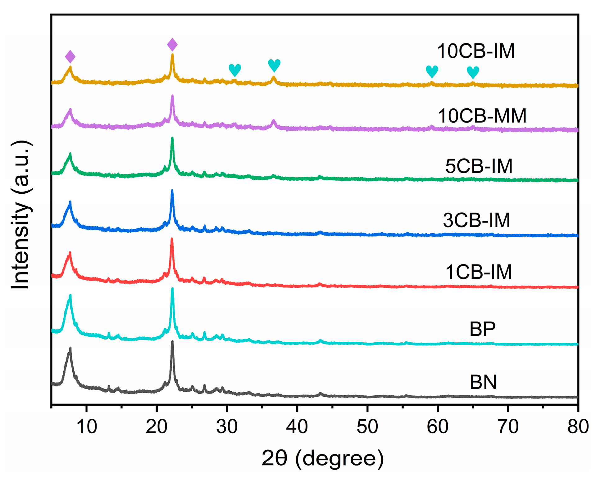
Figure 1 shows the XRD patterns of the Co/Beta catalysts. All these samples exhibit typical diffraction peaks of Beta zeolite at 2θ = 7.3° and 22.2° (marked with rhomboid, JCPDS 48-0074), indicating that the samples contain the Beta zeolite phase as the support of Co/Beta catalysts with high crystallinity [
12,
13]. Moreover, for the Co/Beta series catalysts prepared via the impregnation method, the diffraction peaks at 2θ = 7.3° and 22.2° decreased gradually with the increase in cobalt loading, which indicated that the characteristic diffraction peaks of Beta zeolites were weakened after loading cobalt. The catalyst is composed of cobalt oxide and Beta zeolite, and when the cobalt loading amount increases, the proportion of Beta zeolite crystal phase in the whole catalyst crystal decreases, so the characteristic diffraction peak intensity of Beta zeolite crystal phase decreases gradually. In addition, compared with the sample BN, it is found that the samples 5CB-IM, 10CB-IM and 10CB-MM show weaker characteristic diffraction peaks at 2θ = 31.7°, 36.9°, 59.4° and 65.4° (marked with heart), which were attributed to (220), (311), (511) and (440) reflections of Co
3O
4, and the diffraction peak of these angles increases with the increase in cobalt loading [
14]. The above XRD characterization shows that we have successfully prepared Co/Beta catalysts via the impregnation method and melting method.
In order to characterize the crystal size and morphology of the catalysts, a series of Co-Beta catalysts were characterized by SEM, as shown in
Figure 2. It can be seen from
Figure 2 that the crystal size of the original Beta zeolite BP sample is about the same as the larger particles of 200 nm, the surface of the zeolite particles is relatively smooth, and the particle morphology shows a relatively regular approximate octahedral morphology. After treatment with a higher concentration of nitric acid, whether 1CB-IM and 10CB-IM prepared via the impregnation method or 10CB-MM prepared via the melting method, the catalyst samples show rough nanocrystalline-morphology, and the secondary particles of 200 nm each are formed by the primary particles of 20–30 nm. This is because during the dealumination and partial dissolution of Beta zeolite in the acid treatment, the morphology of catalysts are changed, the surface becomes rougher, some zeolites appears holes after etching, and some zeolites are dissolved into smaller grains and accumulate to form a nanocrystalline-aggregated morphology. And, the accumulation of 20–30 nm nanoparticles produces a large number of intercrystalline mesopores [
15,
16]. Thus, the hierarchical Co/Beta zeolite catalyst with a nanocrystalline-aggregated structure was formed.
Figure 3 shows the TEM images of Co-Beta series of catalysts. It can be seen from
Figure 3 that the crystal size of the original Beta zeolite BP sample is about 200 nm, and the surface of the zeolite particles is relatively smooth, and the particle morphology shows approximate octahedral morphology. After acid treatment and Co impregnation, 1CB-IM and 10CB-IM prepared via the impregnation method show rough nanocrystalline-aggregated morphology, and the secondary particle of 200 nm is formed by the primary particles of 20–50 nm. Meanwhile, with acid treatment and cobalt melting, 10CB-MM prepared via the melting method show a rough nanocrystalline-aggregated morphology with a loose and porous morphology, and the secondary particle of 150 nm is formed by the primary particles of 20–30 nm. This is caused by a high concentration of nitric acid treatment. During the acid treatment, the framework aluminums of Beta zeolite are partially removed, and the Beta zeolite particles are partially dissolved and become smaller. This process forms large numbers of intercrystalline mesopores and obtains a hierarchical Co/Beta catalyst with nanocrystalline-aggregated morphology [
15,
17]. By observing the TEM images of the 10CB-MM and 10CB-IM catalyst samples with high magnification (
Figure S1), it is found that the cobalt species particles of the 10CB-MM samples prepared via the melting method are smaller and more uniformly dispersed, with a particle size of about 5–10 nm, while that of the 10CB-IM samples prepared via the impregnation method is larger, with a particle size of about 8–20 nm.
The pore structure properties of Co/Beta series catalysts were determined by N
2 adsorption–desorption method. The N
2 adsorption–desorption isotherms of different samples are shown in
Figure 4. The total surface areas of different samples were calculated by the Brunauer–Emmett–Teller (BET) method. The internal/external surface area and micropore volume were determined by the t-plot method, while the mesopore volume was determined by the BJH method. As shown in
Figure 4 and
Table 1, compared with the sample BP before acid treatment and the sample BN after acid treatment, it was found that the surface area and pore volume of Beta zeolite increased after acid treatment; in particular, the mesopore volume increased obviously. Combined with the TEM characterization results, we can know this is due to the dealumination and partial dissolution of Beta zeolites treated with nitric acid, resulting in the accumulation of nanocrystals and the formation of a large number of intercrystalline mesopores. At the same time, all samples have a H3 hysteresis ring, which indicates that the mesoporous pore size distribution of catalyst samples is uneven and the pore size distribution range is wide. This is due to the uncontrollable mesoporous morphology, size and distribution produced by acid treatment, which can also be reflected in the pore size distribution curves below. This can be further confirmed by the characterization results of TEM (
Figure 3 and
Figure S1).
The textural properties of these samples are listed in
Table 1. Compared with the BP sample without acid treatment, the total surface area, total pore volume and mesopore volume of acid-treated BN samples are significantly increased. Such high specific surface area (515 m
2/g) and mesoporous volume (0.44 cm
3/g) of BN sample are attributed to the well-developed intercrystalline mesoporous channels provided by a nanocrystalline-aggregated structure formed by acid treatment. As a catalyst support, this zeolite greatly improves the diffusion and mass transfer performance of the catalyst, and is beneficial to improve the catalytic performance of syngas (CO and H
2) to aviation kerosene. With increasing Co loading amount, the external surface area and mesopore volume of the xCB-IM samples present a slightly decreasing trend. This is because the impregnated cobalt ions exchange with protons in the zeolite and generate CoO
x species after calcination, and are small and easily mobile. The small CoO
x species can migrate to the intercrystalline mesopore and external surface, gather and grow, resulting in a decrease in the external surface area and mesopore volume, while for the 10CB-MM samples prepared via the melting method, cobalt nitrate hexahydrate is in the melting state at 80 °C and has a certain fluidity, which can penetrate into the micropores and mesoporous channels of Beta zeolites. After calcination, cobalt oxide nanoparticles with good dispersion can be carried out on the inner and outer surface of the pores of Beta zeolites, thus reducing the specific surface area of Beta zeolites and reducing the volume of micropores and mesoporous pores.
The pore size distributions of BJH models for different catalyst samples are shown in
Figure 5. The BN of acid-treated Beta zeolite samples contains mesoporous pores in the range of 5–30 nm, which is due to the dealumination and partial dissolution of Beta zeolite samples with acid treatment, forming the morphology of nanocrystalline-aggregated structure. The process of dealumination and partial dissolution is random, resulting in irregular 5–30 nm mesoporous channels with wide pore size distribution. Using acid-treated Beta zeolite as support, the pore size distribution of xCB-IM series catalysts prepared via the impregnation method is basically the same as that of BN samples, with mesoporous channels in the range of 5–30 nm. At the same time, it can be seen from
Figure 5 that, compared with BN samples, the peak height of pore size distribution curve decreases with the increase in cobalt loading. This is due to the fact that with the increase in cobalt loading, more cobalt oxide particles enter into the mesoporous channels of zeolites, blocking part of the mesoporous channels, resulting in a decrease in the number of mesopores. Compared with the 10CB-IM samples prepared via the impregnation method, the pore size distribution of the 10CB-MM samples prepared via the melting method shifted from 5–30 nm to 6–40 nm.
Ammonia temperature-programmed desorption (NH
3-TPD) is often used to characterize the acid properties of analytical catalysts. As a basic molecule, ammonia can be adsorbed on the acidic sites of the catalyst. The increase in ammonia desorption temperature is accompanied by the increase in the acid strength of the acid center [
16]. The ammonia desorption peaks of catalysts can be divided into three types according to the temperature range: weak acid peak (20–200 °C), medium–strong acid peak (200–360 °C) and strong acid peak (360–550 °C) [
18,
19,
20,
21,
22].
In this work, NH
3-TPD was used to characterize the acid content and acid strength of the Co/Beta catalysts. The NH
3-TPD curve and acid quantity fitting results of different samples are shown in
Figure S2 and
Table 2, respectively. First, it can be seen from
Figure S2 and
Table 2 that the acid-treated Beta zeolite BN samples have a high strong acid content and weak acid content. According to the literature report, if the strong acid content of zeolite catalyst is too high, it will improve the catalytic cracking activity, make the hydrocarbon distribution of Fischer–Tropsch products shift to the low-carbon products and improve the selectivity of low-carbon products such as methane and C
2-C
7, which is not conducive to enhancing C
8-C
16 hydrocarbon selectivity [
23]. The SiO
2/Al
2O
3 of the original Beta zeolite is 25, which contains large numbers of strong acid sites. In order to reduce the strong acid content of the Beta zeolite, we pretreated the Beta zeolite with a high concentration of nitric acid. The acid treatment can greatly remove framework aluminum of the Beta zeolite and reduce the strong acid content of the zeolite. At the same time, strong acid treatment can also partially dissolve Beta zeolite particles, form nanocrystalline-aggregated structure and improve the mesoporous content and diffusivity of the catalyst. Thus, Co-Beta catalysts with suitable acid properties and hierarchical pore properties are obtained.
For the xCB-IM series catalysts prepared via the impregnation method, with the increase in cobalt loading, the amount of strong acid decreased gradually, while the amount of medium acid increased gradually. The reduction in strong acidity and increase in medium acidity is ascribed to the interaction between Co2+ ions and strong acid sites (Si–OH–Al), which could generate new medium acid sites. Moreover, the interaction between large CoOx nanoparticles and strong acid sites can also reduce the strong acid amount and increase the medium strong acid amount. The 10CB-MM sample prepared via the melting method also shows a reduction in strong acid sites and an increase in medium acid sites, which is caused by the interaction between small CoOx nanoparticles and strong acid sites during the melting and calcination process. Because the acid property of the catalyst has an important influence on the catalytic performance of syngas-to-aviation kerosene, the acid strength and acid content of the catalyst are adjusted by acid treatment and metal cobalt oxide loading. The product distribution of the reaction from syngas (CO and H2) to aviation kerosene can be indirectly controlled. The structure–activity relationship between the acid properties and catalytic performance of catalysts will be further studied in the form of catalytic tests.
Figure 6 shows the UV-Vis spectra of different samples. For Beta zeolite BN samples, the absorption curve is almost a horizontal straight line, and there is no characteristic absorption band. For the sample xCB-IM, prepared via the impregnation method, the absorption band fluctuates in the range of 400–800 nm. The characteristic band produced when the absorption band is in the range of 400–550 nm and 600–750 nm is assigned to the ligand-metal charge transfer of O
2−→Co
2+ and O
2−→Co
3+ in Co
3O
4 [
24]. The above results showed that the samples prepared via the impregnation method all contained Co
2+ and Co
3+. It was observed that the absorption band heights of 440 nm, 505 nm, 650 nm, 700 nm and 745 nm increased with the increase in cobalt loading, indicating that the content of Co
3O
4 on the catalyst also increased [
25]. The UV spectra of the 10CB-MM samples prepared via the melting method are similar to those of the 10CB-IM samples prepared via the impregnation method, indicating that 10CB-MM samples prepared via the melting method also contain Co
3O
4 species.
The reducibility of cobalt species in Co/Beta series catalysts can be analyzed by H
2-TPR characterization of 1CB-IM, 10CB-IM and 10CB-MM, as shown in
Figure 7. Generally, there are two reduction peaks at different positions in the three catalyst samples, and the two reduction peaks belong to the reduction peaks of Co
3+ ion to Co
2+ ion and Co
2+ ion to Co
0, indicating the valence change process of cobalt species from Co
3O
4 to CoO and then to elemental Co [
25,
26].
In addition, the position of the H2-TPR reduction peak reflects the reducibility of the catalyst. Compared with the 10CB-IM samples prepared via the impregnation method, the positions of the two reduction peaks of the 10CB-MM samples prepared via the melting method move forward as a whole, which indicates that the Co3O4 species of the samples prepared via the melting method are more easily reduced under the same cobalt loading, which is attributed to the interaction between the Co3O4 species and the support of the catalyst prepared via the melting method being weak, so it is more easily reduced. However, some cobalt ion species of the catalysts prepared by impregnation have a strong interaction with the Si–OH–Al acid sites of zeolites, and the particle size of Co3O4 species is larger, which makes it more difficult to reduce the cobalt species. By comparing the samples with different loading via the impregnation method, it is found that the first peak temperature of the reduction peak of the 10CB-IM samples is lower than that of the 1CB-IM samples, while the second peak temperature of the reduction peak of 10CB-IM samples is higher than that of the 1CB-IM samples. The results show that the 10CB-IM samples contain both easy-to-reduce Co3O4 species and difficult-to-reduce Co3O4 species, which is due to the uneven particle size of Co3O4 species in the high-loading 10CB-IM catalyst samples prepared via the impregnation method.
The catalytic performance of different samples for syngas-to-aviation kerosene is shown in
Table 3. Firstly, 0.5g catalyst is reduced for 8 h at 400 °C in hydrogen stream. After the catalyst is reduced, the raw material of syngas with H
2/CO volume ratio of 2 is injected at the gas flow rate of 26 mL/min and reacted for 24 h at the temperature of 230 °C; the GHSV is 3120 mL/(g
cat·h), and the pressure is 3 MPa. The product analysis results of the catalyst reaction for 24 h are listed in
Table 3. And, the CO conversions with time on stream of different samples are shown in
Figure 8.
During the whole reaction period, the conversion of 1CB-IM sample remains at a low level (
Figure 8). After 24 h of reaction, the conversion of CO hydrogenation is only 2.2%, and the CH
4 selectivity is the highest, while the selectivity of C
8-C
16 aviation kerosene component is the lowest. This is because cobalt is the active center for initiating a CO hydrogenation reaction and chain growth reaction [
27], the cobalt loading of 1CB-IM sample is too low (1 wt%), the number of active sites for CO hydrogenation reaction and chain growth reaction is insufficient, resulting in a low CO conversion.
As seen in
Figure 8, comparing the 10CB-MM sample prepared via the melting method and the 10CB-IM sample prepared via the impregnation method, we can find the CO conversion of the 10CB-MM sample is higher than that of the 10CB-IM sample during the whole reaction period. Meanwhile, the declining rate of conversion of the 10CB-MM sample is slower than that of the 10CB-IM sample, indicating that the 10CB-MM sample has a higher CO hydrogenation catalytic activity and stability than the 10CB-IM sample.
For the xCB-IM series catalysts prepared via the impregnation method, the CO conversion and the selectivity of the C
8-C
16 component both increase with the increase in cobalt loading, and the mole ratio of olefin and paraffin (O/P) in the C
8-C
16 products gradually decrease with the increase in cobalt loading (
Table 3). The increase in CO conversion and the decrease in O/P are due to the fact that cobalt is the active center for catalytic initiation of CO hydrogenation reaction and chain growth reaction [
27]. With the increase in cobalt loading, the number of active centers for CO conversion and hydrogenation reaction is increasing [
28,
29,
30]. On the one hand, it can continuously increase the CO conversion. On the other hand, it can also promote the hydrogenation of olefins, improve the alkane selectivity, reduce the olefin selectivity and lead to the decrease in the O/P ratio.
In addition, the increasing selectivity of the C
8-C
16 component is due to the increasing trend of cobalt species particle size with the increase in cobalt loading. The larger the cobalt species size, the weaker the interaction between the cobalt species and Beta zeolite support, and the more easily it is reduced, which is beneficial for the improvement in the selectivity of high-carbon-number hydrocarbons [
31]. Moreover, with the increase in cobalt loading, the amount of strong acid in the catalyst decreases gradually, and the amount of medium acid increases gradually, and the decrease in strong acid content is beneficial to inhibit the catalytic cracking of Fischer–Tropsch synthesis products. Thus, it is beneficial for the distribution of Fischer–Tropsch synthesis products to move to high-carbon-number hydrocarbon products [
23].
Compared with the 10CB-IM samples prepared via the impregnation method, the 10CB-MM catalyst samples prepared via the melting method have higher CO conversion and C
8-C
16 aviation kerosene component selectivity and a lower O/P ratio. After 24 h of reaction, the CO conversion of the 10CB-MM catalyst prepared via the melting method reaches 34.6%. The selectivity of the C
8-C
16 aviation kerosene component is 40.2%. This is due to the fact that the 10CB-MM sample prepared via the melting method is equivalent to the 10CB-IM sample prepared via the impregnation method. The CoO
x species prepared via the melting method has a smaller particle size, higher dispersion, easier reduction, higher CO hydrogenation and chain growth catalytic activity, more suitable acid strength and acid content, and can cut long-chain hydrocarbon molecules into short-chain hydrocarbon molecule products in the C
8-C
16 range through an appropriate amount of strong acid sites. As a result, the selectivity of the C
8-C
16 aviation kerosene component in the catalytic products is higher, and the O/P ratio is lower [
23,
31].
This process can achieve the goal of direct and highly selective preparation of aviation kerosene hydrocarbon products from syngas (CO and H2) without subsequent complex processing steps such as hydrocracking and hydrofining, which provides a new idea for the production of aviation kerosene in the Fischer–Tropsch synthesis industry.


