
Effect of Waste Iron Filings (IF) on Radiation Shielding Feature of Polyepoxide Composites

(This article belongs to the Section Hybrid and Composite Crystalline Materials)
Abstract
:1. Introduction
2. Materials and Method
2.1. Materials
2.2. Epoxy Resin
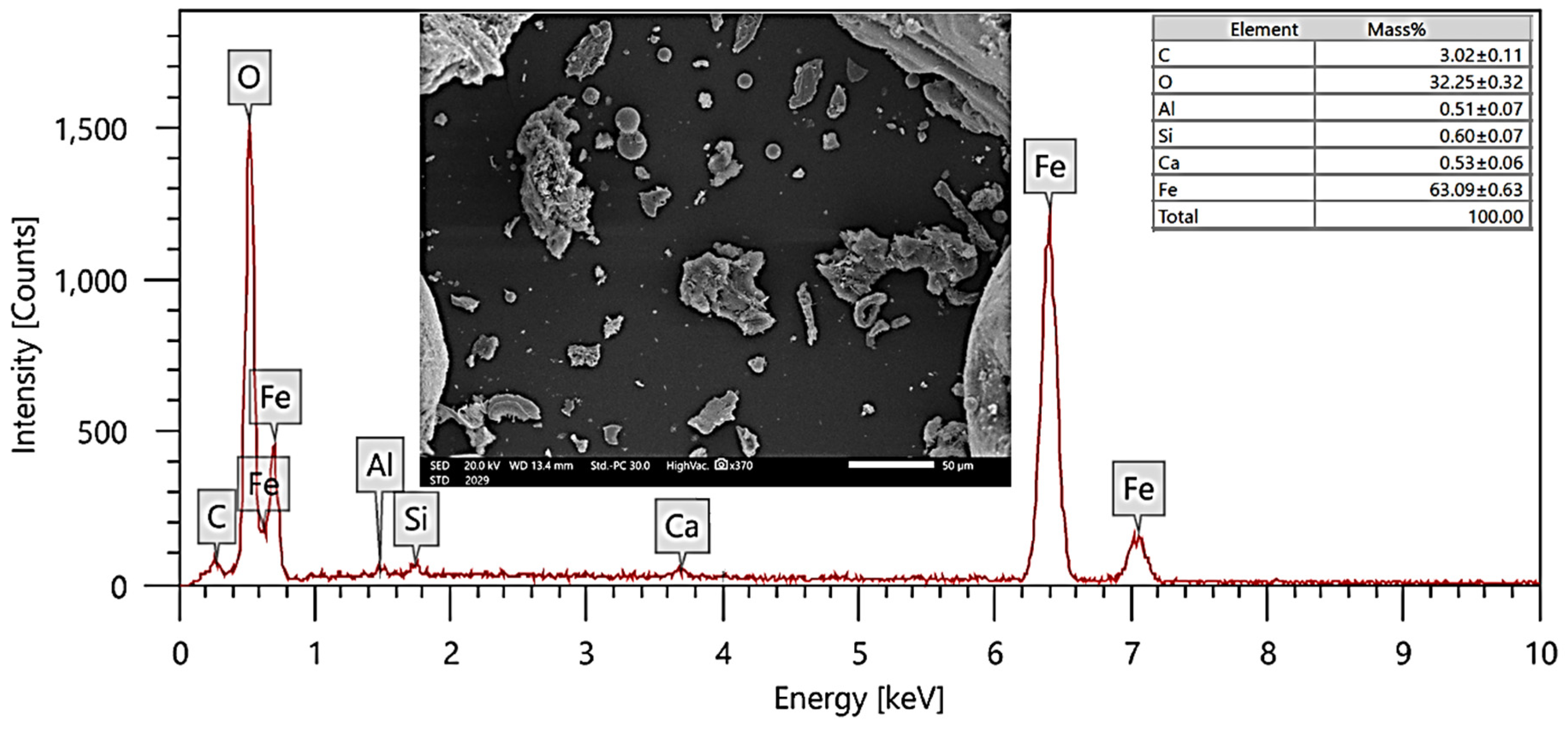
2.3. Iron Filings
3. Methods
3.1. Composite Preparation
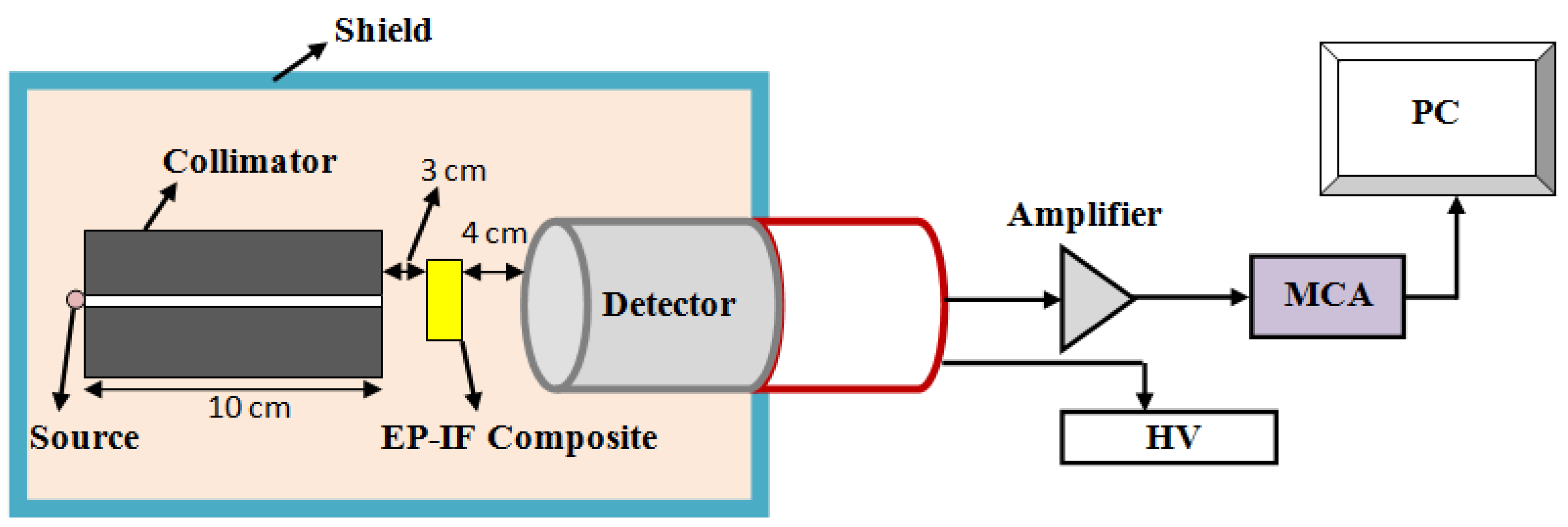
3.2. Radiation Shielding Measurements
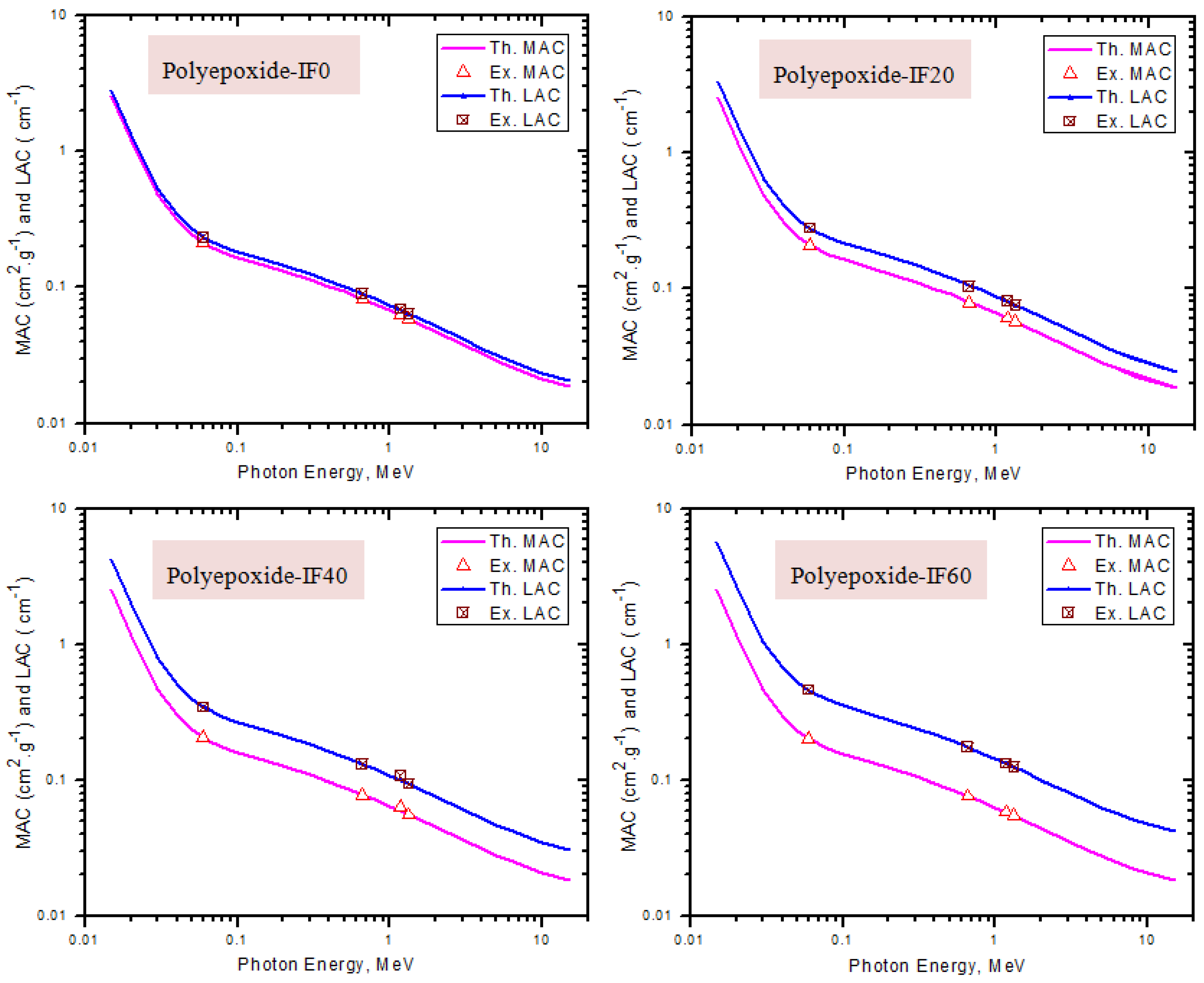
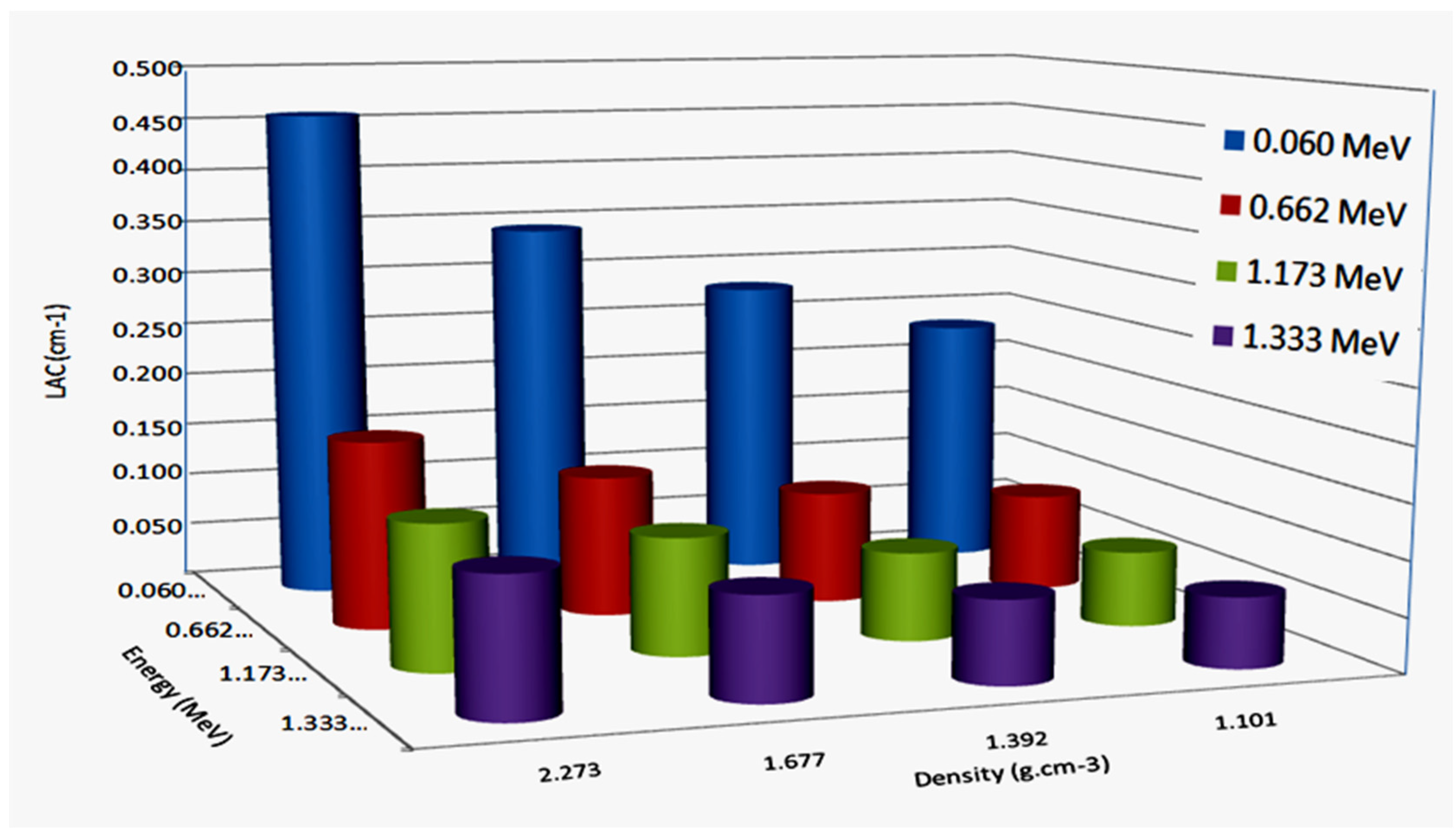
4. Results and Discussion
5. Conclusions
Author Contributions
Funding
Data Availability Statement
Conflicts of Interest
References
- Tijani, S.A.; Al-Hadeethi, Y.F. The use of isophthalic-bismuth polymer composites as radiation shielding barriers in nuclear medicine. Mater. Res. Express 2019, 6, 055323. [Google Scholar] [CrossRef]
- Chaiphaksa, W.; Borisut, P.; Chanthima, N.; Kaewkhao, J.; Sanwaranatee, N.W. Mathematical calculation of gamma rays interaction in bismuth gadolinium silicate glass using WinXCom program. Mater. Today Proc. 2022, 65, 2412–2415. [Google Scholar] [CrossRef]
- Kaewjaeng, S.; Kothan, S.; Chaiphaksa, W.; Chanthima, N.; Rajaramakrishna, R.; Kim, H.J.; Kaewkhao, J. High transparency La2O3-CaO-B2O3-SiO2 glass for diagnosis x-rays shielding material application. Radiat. Phys. Chem. 2019, 160, 41–47. [Google Scholar] [CrossRef]
- Araz, A.; Kavaz, E.; Durak, R. Neutron and photon shielding competences of aluminum open-cell foams filled with different epoxy mixtures: An experimental study. Radiat. Phys. Chem. 2021, 182, 109382. [Google Scholar] [CrossRef]
- Abouhaswa, A.S.; Kavaz, E. Bi2O3 effect on physical, optical, structural and radiation safety characteristics of B2O3-Na2O-ZnO-CaO glass system. J. Non-Cryst. Solids 2020, 535, 119993. [Google Scholar] [CrossRef]
- Rajesh, M.; Kavaz, E. Photoluminescence, radiative shielding properties of Sm3+ ions doped fluoroborosilicate glasses for visible (reddish-orange) display and radiation shielding applications. Mater. Res. Bull. 2021, 142, 111383. [Google Scholar] [CrossRef]
- Kamislioglu, M. An investigation into gamma radiation shielding parameters of the (Al:Si) and (Al+Na):Si-doped international simple glasses (ISG) used in nuclear waste management, deploying Phy-X/PSD and SRIM software. J. Mater. Sci. Mater. Electron. 2021, 32, 12690–12704. [Google Scholar] [CrossRef]
- Kamislioglu, M. Research on the effects of bismuth borate glass system on nuclear radiation shielding parameters. Results Phys. 2021, 22, 103844. [Google Scholar] [CrossRef]
- Mahmoud, I.S.; Issa, S.A.; Saddeek, Y.B.; Tekin, H.O.; Kilicoglu, O.; Alharbi, T.; Sayyed, M.I.; Erguzel, T.T.; Elsaman, R. Gamma, neutron shielding and mechanical parameters for lead vanadate glasses. Ceram. Int. 2019, 45, 14058–14072. [Google Scholar] [CrossRef]
- Al-Hadeethi, Y.; Sayyed, M.I. Radiation attenuation properties of Bi2O3–Na2O–V2O5–TiO2–TeO2 glass system using Phy-X/PSD software. Ceram. Int. 2020, 46, 4795–4800. [Google Scholar] [CrossRef]
- Naseer, K.A.; Sathiyapriya, G.; Marimuthu, K.; Piotrowski, T.; Alqahtani, M.S. Optical, elastic, and neutron shielding studies of Nb2O5 varied Dy3+ doped barium-borate glasses. Optik 2022, 251, 168436. [Google Scholar] [CrossRef]
- Karabul, Y.; İçelli, O. The assessment of usage of epoxy based micro and nano-structured composites enriched with Bi2O3 and WO3 particles for radiation shielding. Results Phys. 2021, 26, 104423. [Google Scholar] [CrossRef]
- Prasad, R.; Pai, A.R.; Oyadiji, S.O.; Thomas, S.; Parashar, S.K.S. Utilization of hazardous red mud in silicone rubber/MWCNT nanocomposites for high performance electromagnetic interference shielding. J. Clean. Prod. 2022, 377, 134290. [Google Scholar] [CrossRef]
- Aldhuhaibat, M.J.; Amana, M.S.; Jubier, N.J.; Salim, A.A. Improved gamma radiation shielding traits of epoxy composites: Evaluation of mass attenuation coefficient, effective atomic and electron number. Radiat. Phys. Chem. 2021, 179, 109183. [Google Scholar] [CrossRef]
- Li, R.; Gu, Y.; Zhang, G.; Yang, Z.; Li, M.; Zhang, Z. Radiation shielding property of structural polymer composite: Continuous basalt fiber reinforced epoxy matrix composite containing erbium oxide. Compos. Sci. Technol. 2017, 143, 67–74. [Google Scholar] [CrossRef]
- Olutoge, F.A.; Onugba, M.A.; Ocholi, A. Strength Properties of Concrete Produced with Iron Filings as Sand Replacement. Br. J. Appl. Sci. Technol. 2016, 18, 1–6. [Google Scholar] [CrossRef]
- Miah, M.J.; Ali, M.K.; Paul, S.C.; John Babafemi, A.; Kong, S.Y.; Šavija, B. Effect of Recycled Iron Powder as Fine Aggregate on the Mechanical, Durability, and High Temperature Behavior of Mortars. Materials 2020, 13, 1168. [Google Scholar] [CrossRef] [PubMed] [Green Version]
- Helmand, P.; Saini, S. Mechanical properties of concrete in presence of Iron filings as complete replacement of fine aggregates. Mater. Today Proc. 2019, 15, 536–545. [Google Scholar]
- Madugu, I.A.; Abdulwahab, M.; Aigbodion, V.S. Effect of iron fillings on the properties and microstructure of cast fiber–polyester/iron filings particulate composite. J. Alloys Compd. 2009, 476, 807–811. [Google Scholar] [CrossRef]
- Abushammala, H.; Mao, J. Waste Iron Filings to Improve the Mechanical and Electrical Properties of Glass Fiber-Reinforced Epoxy (GFRE) Composites. J. Compos. Sci. 2023, 7, 90. [Google Scholar] [CrossRef]
- Rana, S.; Alagirusamy, R.; Joshi, M. A Review on Carbon Epoxy Nanocomposites. J. Reinf. Plast. Compos. 2009, 28, 461–487. [Google Scholar] [CrossRef]
- Petrović, J.M.; Bekrić, D.; Vujičić, I.T.; Dimić, I.; Putić, S. Microstructural Characterization of Glass-Epoxy Composites Subjected to Tensile Testing. Acta Period. Technol. 2013, 44, 151–162. [Google Scholar] [CrossRef] [Green Version]
- Sayyed, M.I.; Yasmin, S.; Almousa, N.; Elsafi, M. Shielding Properties of Epoxy Matrix Composites Reinforced with MgO Micro- and Nanoparticles. Materials 2022, 15, 6201. [Google Scholar] [CrossRef] [PubMed]
- Elsafi, M.; Almousa, N.; Almasoud, F.I.; Almurayshid, M.; Alyahyawi, A.R.; Sayyed, M.I. A Novel Epoxy Resin-Based Composite with Zirconium and Boron Oxides: An Investigation of Photon Attenuation. Crystals 2022, 12, 1370. [Google Scholar] [CrossRef]
- Elsafi, M.; Almousa, N.; Al-Harbi, N.; Almutiri, M.N.; Yasmin, S.; Sayyed, M.I. Ecofriendly and radiation shielding properties of newly developed epoxy with waste marble and WO3 nanoparticles. J. Mater. Res. Technol. 2023, 22, 269–277. [Google Scholar] [CrossRef]
- Sayyed, M.I.; Hamad, M.K.; Mhareb, M.H.A.; Kurtulus, R.; Dwaikat, N.; Saleh, M.; Elsafi, M.; Taki, M.M.; Kavas, T.; Ziq, K.A.; et al. Assessment of radiation attenuation properties for novel alloys: An experimental approach. Radiat. Phys. Chem. 2022, 200, 110152. [Google Scholar] [CrossRef]
- Almuqrin, A.H.; Sayyed, M.I.; Elsafi, M.; Khandaker, M.U. Comparison of radiation shielding ability of Bi2O3 micro and nanoparticles for radiation shields. Radiat. Phys. Chem. 2022, 200, 110170. [Google Scholar] [CrossRef]
- Aloraini, D.A.; Sayyed, M.I.; Mahmoud, K.A.; Almuqrin, A.A.; Kumar, A.; Khandaker, M.U.; Elsafi, M. Evaluation of radiation shielding characteristics of B2O3–K2O–Li2O-HMO (HMO = TeO2/SrO/PbO/Bi2O3) glass system: A simulation study using MCNP5 code. Radiat. Phys. Chem. 2022, 200, 110172. [Google Scholar] [CrossRef]
- Al-Harbi, N.; Sayyed, M.I.; Al-Hadeethi, Y.; Kumar, A.; Elsafi, M.; Mahmoud, K.A.; Khandaker, M.U.; Bradley, D.A. A novel CaO–K2O–Na2O–P2O5 glass systems for radiation shielding applications. Radiat. Phys. Chem. 2021, 188, 109645. [Google Scholar] [CrossRef]
- D’souza, A.N.; Sayyed, M.I.; Karunakara, N.; Al-Ghamdi, H.; Almuqrin, A.H.; Elsafi, M.; Khandaker, M.U.; Kamath, S.D. TeO2 SiO2–B2O3 glasses doped with CeO2 for gamma radiation shielding and dosimetry application. Radiat. Phys. Chem. 2022, 200, 110233. [Google Scholar] [CrossRef]
- Sayyed, M.I.; Alrashedi, M.F.; Almuqrin, A.H.; Elsafi, M. Recycling and optimizing waste lab glass with Bi2O3 nanoparticles to use as a transparent shield for photons. J. Mater. Res. Technol. 2022, 17, 2073–2083. [Google Scholar] [CrossRef]
- Al-Hadeethi, Y.; Sayyed, M.I.; Barasheed, A.Z.; Ahmed, M.; Elsafi, M. Preparation and radiation attenuation properties of ceramic ball clay enhanced with micro and nano ZnO particles. J. Mater. Res. Technol. 2022, 17, 223–233. [Google Scholar] [CrossRef]
- Hannachi, E.; Sayyed, M.I.; Slimani, Y.; Elsafi, M. Experimental investigation on the physical properties and radiation shielding efficiency of YBa2Cu3Oy/M@M3O4 (M = Co, Mn) ceramic composites. J. Alloys Compd. 2022, 904, 164056. [Google Scholar] [CrossRef]
- Hannachi, E.; Sayyed, M.I.; Slimani, Y.; Almessiere, M.A.; Baykal, A.; Elsafi, M. Synthesis, characterization, and performance assessment of new composite ceramics towards radiation shielding applications. J. Alloys Compd. 2022, 899, 163173. [Google Scholar] [CrossRef]
- Al-Yousef, H.A.; Alotiby, M.; Hanfi, M.Y.; Alotaibi, B.M.; Mahmoud, K.A.; Sayyed, M.I.; Al-Hadeethi, Y. Effect of the Fe2O3 addition on the elastic and gammaray shielding features of bismuth sodium-borate glass system. J. Mater. Sci. Mater. Electron. 2021, 32, 6942–6954. [Google Scholar] [CrossRef]
- Almutairi, H.M.; Al-Saleh, W.M.; Abualsayed, M.I.; Elsafi, M. Effect of Cerium (IV) Oxide Particle Size on Polydimethylsiloxane Polymer to Form Flexible Materials against Ionizing Radiation. Polymers 2023, 15, 2883. [Google Scholar] [CrossRef]
- Albarzan, B.; Hanfi, M.Y.; Almuqrin, A.H.; Sayyed, M.I.; Alsafi, H.M.; Mahmoud, K.A. The Influence of Titanium Dioxide on Silicate-Based Glasses: An Evaluation of the Mechanical and Radiation Shielding Properties. Materials 2021, 14, 3414. [Google Scholar] [CrossRef]
- Alresheedi, M.T.; Elsafi, M.; Aladadi, Y.T.; Abas, A.F.; Ganam, A.B.; Sayyed, M.I.; Mahdi, M.A. Mechanical, Morphological, Thermal and the Attenuation Properties of Heavy Mortars Doped with Nanoparticles for Gamma-Ray Shielding Applications. Materials 2023, 16, 3255. [Google Scholar] [CrossRef] [PubMed]
- Alresheedi, M.T.; Elsafi, M.; Aladadi, Y.T.; Abas, A.F.; Ganam, A.B.; Sayyed, M.I.; Mahdi, M.A. Assessment of Silicone Rubber/Lead Oxide Composites Enriched with Bi2O3, WO3, BaO, and SnO2 Nanoparticles for Radiation Shielding Applications. Polymers 2023, 15, 2160. [Google Scholar] [CrossRef]
- Bashter, I.I. Calculation of radiation attenuation coefficients for shielding concretes. Ann. Nucl. Energy 1997, 24, 1389. [Google Scholar] [CrossRef]
- NBSIR 87-3597; XCOM: Photon Cross Sections on a Personal Computer. National Institute of Standards: Gaithersburg, MD, USA, 1987.
- Şakar, E.; Özpolat, Ö.F.; Alım, B.; Sayyed, M.I.; Kurudirek, M. Phy-X/PSD: Development of a user friendly online software for calculation of parameters relevant to radiation shielding and dosimetry. Radiat. Phys. Chem. 2020, 166, 108496. [Google Scholar] [CrossRef]
- Tekin, H.O.; Abouhaswa, A.S.; Kilicoglu, O.; Issa, S.A.M.; Akkurt, I.; Rammah, Y.S. Fabrication, physical characteristic, and gamma-photon attenuation parameters of newly developed molybdenum reinforced bismuth borate glasses. Phys. Scr. 2020, 95, 115703. [Google Scholar] [CrossRef]
- Singh, P.S.; Singh, T.; Kaur, P. Variation of energy absorption buildup factors with incident photon energy and penetration depth for some commonly used solvents. Ann. Nucl. Energy 2008, 35–36, 1093–1097. [Google Scholar] [CrossRef]
- ANSI/ANS-6.4.3; Gamma Ray Attenuation Coefficient and Buildup Factors for Engineering Materials. American Nuclear Society: La Grange Park, IL, USA, 1991.


| Composite Code | Composition (wt %) | Density (g·cm−3) | |
|---|---|---|---|
| Epoxy Resin | Iron Filings | ||
| EP–IF0 | 100 | 0 | 1.100 ± 0.009 |
| EP–IF20 | 80 | 20 | 1.329 ± 0.014 |
| EP–IF40 | 60 | 40 | 1.677 ± 0.007 |
| EP–IF60 | 40 | 60 | 2.273 ± 0.011 |
| Equation Number | Parameter | Equation | Remarks |
|---|---|---|---|
| (1) | Linear attenuation coefficient | t: thickness of absorber composite | |
| (2) | Mass attenuation coefficient | : density of absorber composite | |
| (3) | Mean free path | ||
| (4) | Half value layer | ||
| (5) | Tenth value layer | ||
| (6) | Radiation shielding efficiency | ||
| (7) | Lead equivalent thickness | ||
| (8) | Effective atomic number | where the total atomic cross-section The electronic cross-section | |
| (9) | Electronic density | NA, Avogadro’s number | |
| (10) | Equivalent atomic number | where Z1 and Z2 represent the element’s atomic number that corresponds to the ratio R1 and R2, respectively, and | |
| (11) | GP fitting parameter | ||
| (12) | Exposure buildup factor | or | where X is the depth of penetration and E is the initial gamma energy |
| (13) | Fast neutron removal cross-section | is the removal cross-section of the ith component |
Disclaimer/Publisher’s Note: The statements, opinions and data contained in all publications are solely those of the individual author(s) and contributor(s) and not of MDPI and/or the editor(s). MDPI and/or the editor(s) disclaim responsibility for any injury to people or property resulting from any ideas, methods, instructions or products referred to in the content. |
© 2023 by the authors. Licensee MDPI, Basel, Switzerland. This article is an open access article distributed under the terms and conditions of the Creative Commons Attribution (CC BY) license (https://creativecommons.org/licenses/by/4.0/).
Share and Cite
Alresheedi, M.T.; Elsafi, M. Effect of Waste Iron Filings (IF) on Radiation Shielding Feature of Polyepoxide Composites. Crystals 2023, 13, 1168. https://doi.org/10.3390/cryst13081168
Alresheedi MT, Elsafi M. Effect of Waste Iron Filings (IF) on Radiation Shielding Feature of Polyepoxide Composites. Crystals. 2023; 13(8):1168. https://doi.org/10.3390/cryst13081168
Chicago/Turabian StyleAlresheedi, Mohammed T., and Mohamed Elsafi. 2023. "Effect of Waste Iron Filings (IF) on Radiation Shielding Feature of Polyepoxide Composites" Crystals 13, no. 8: 1168. https://doi.org/10.3390/cryst13081168