Article

Molecular Dynamics Simulation of the Interaction between Dislocations and Iron–Vanadium Precipitates in Alpha Iron: Effect of Chemical Composition

Metallurgy Department, Faculty of Engineering, Materials Research Institute, University of Mons, 20, Place du Parc, 7000 Mons, Belgium
*
Author to whom correspondence should be addressed.
Crystals 2023, 13(8), 1247; https://doi.org/10.3390/cryst13081247
Submission received: 24 July 2023 / Revised: 7 August 2023 / Accepted: 10 August 2023 / Published: 12 August 2023
(This article belongs to the Special Issue Dislocations and Twinning in Metals and Alloys)

Abstract

:
In this study, molecular dynamics simulations were employed to study the interaction between dislocations with Fe-V precipitate with different vanadium concentrations. Increasing the vanadium concentration in the precipitate results in a strong interaction between the dislocations and the precipitate, and the dislocation line bows out more as a result of increasing the energy of the dislocation line, and the critical stress needed for depinning the dislocations increases. However, at a low vanadium concentration (1:3 atomic ratio) the dislocations cut through the precipitate without changing the speed. An increasing vanadium concentration not only affects the dislocation shape and movement speed, but also affects the configuration of the junction between the a/2[111] and a/2[100] dislocations, and the void formation after the cutting process. The formation of strong junctions and a high number of voids locks the a/2[111] dislocation motion, and increases the strength of the alloy. The results of the radial distribution function before and after the cutting process show that the structure of the precipitate changes from crystalline to amorphous, and the degree of amorphization decreases with an increasing vanadium concentration.

1. Introduction

Ultra-high-strength steel (UHSS) and high-speed steel (HSS) have broad applications in numerous industries, due to their high strength. These steels contain various precipitate-forming elements, such as Mo, V, W, C, and Cr, allowing them to develop a high strength and excellent characteristics for performing in different forming processes, such as press working, extrusion, and drawing. Among all of the elements that are added, vanadium shows a high level of solubility for forming the iron-based solid solution Fe1-xVx, with x in the range 0.03 ≤ x ≤ 0.10 [1]. The vanadium consumption in the iron and steel industry represents about 85% of vanadium-bearing products produced worldwide [2]. Studies have shown that increasing the vanadium concentration can increase the strength of the Fe-based alloy through the quenching and tempering process, due to the formation of various precipitates [3].
One of the significant hardening mechanisms in these steels is precipitation hardening, which occurs due to the interaction between dislocations and precipitates. In this regard, molecular dynamics simulation studies yield valuable insights into tracking dislocations within the crystal structure [4].
In the past, many theories have been proposed regarding the effect of precipitates on dislocations, such as the Orowan mechanism, dislocation cutting, and climbing theory [5,6,7,8]. According to the Orowan mechanism, when the dislocation reaches the precipitate during the bypass process, dislocation loops are formed around the precipitate. These loops cause local plastic flow or residual stress, resulting in the strengthening of the alloy against plastic deformation [9,10]. The second theory describes the dislocation cutting through the precipitate. However, this cutting process requires a high amount of energy, which increases the strain rate [11,12]. On the other hand, the climbing theory discusses how, when a dislocation encounters a hard or non-shearable obstacle, it continues the movement on another gliding plane [13,14].
Various elements have exhibited different hardening mechanisms. Researchers have investigated the effect of precipitates on dislocation reactions in α-Fe, based on the aforementioned theories.
Pascuet et al. investigated the effect of the Ni, Mn, and P elements on precipitate hardening, and reported that the stress required for the unpinning of the dislocations would be influenced by atomic segregation in the precipitate [15]. Terentyev, D. et al. demonstrated that, in the mechanism of chromium precipitate hardening, chromium prevents the absorption of the dislocation loop by the dislocation line, thus becoming a significant source of reinforcement [16]. However, in the case of a copper–iron precipitate, a softening in the iron has been reported by Wu, Xiaoyu et al., due to the reorientation of the precipitate during plastic deformation, which weakens the pinning strength of the precipitate [17]. In most molecular dynamics simulation studies, it is generally agreed that a high mechanical strength can be achieved by precipitates that are either softer or harder than the matrix. The most significant strengthening occurs when there is not a substantial difference in the elastic modulus ratio of the precipitate to the matrix [6,18,19,20,21]. All in all, the speed of the dislocation’s movement, and its interaction with metals, determine plastic deformation in alloys. The presence of precipitates in the alloy plays a crucial role in influencing the dislocation movement and, consequently, the plastic deformation behavior.
Even though the effect of various solute elements in the precipitation hardening of α-Fe has been studied, the literature review reveals that no molecular dynamics simulation study on the hardening mechanism of the Fe-V precipitate has been conducted, and even the experimental studies have primarily focused on the formation of vanadium carbide precipitation [22,23]. Therefore, the strength improvement mechanism of the Fe-V precipitate has not been clarified yet.
The molecular dynamics (MDs) simulation plays a crucial role in advancing research across various fields, including material science, biopharmaceuticals, chemical engineering, and physics. The articles provided highlight its significance when studying the behavior of materials at the atomic and molecular levels, enabling a deeper understanding of complex processes. In the context of nanocrystalline materials and nanomachining, MDs simulations have been instrumental in investigating the interactions between grain boundaries and sub-grain boundaries, leading to insights into plastic deformation mechanisms and surface generation processes. Such detailed knowledge is invaluable for optimizing the manufacturing of micro-electro-mechanical systems (MEMSs) and nano-electro-mechanical systems (NEMSs). Additionally, MDs simulations have been extensively applied in the study of thermal energy storage, particularly in phase-change materials (PCMs) and nucleation agents (NAs). The simulations have shed light on the super-cooling phenomenon, guiding the design of efficient thermal energy storage systems. Furthermore, in the study of silicon carbide single-crystal semiconductors, MDs simulations have been employed to investigate the mechanical properties, micro-removal, and super-cooling behavior, providing crucial information to the microelectronics industry [24,25].
The importance of MDs simulation lies in its ability to bridge the gap between experimental observations and theoretical predictions. While experiments can be time-consuming, expensive, and sometimes difficult to perform at the atomic level, MDs simulations offer a cost-effective and reliable alternative. They provide access to microscopic details that are otherwise challenging to observe, allowing researchers to study complex phenomena, and design novel materials with tailored properties. MDs simulations have become an indispensable tool for elucidating the underlying mechanisms and guiding the development of cutting-edge technologies [26].
Moreover, the versatility of MDs simulations in exploring different materials and systems is evident from the diverse range of applications discussed in the articles. From investigating crystallization processes in phase-change materials, to understanding the intricate interactions between materials in nanocrystalline systems, MDs simulations offer a unique and comprehensive perspective. The capability of MDs simulations to capture thermal fluctuations, nucleation events, and complex molecular interactions empowers researchers to make informed decisions and predictions, accelerating progress in multiple scientific disciplines. As the computing speed of computers continues to improve, and MDs theories evolve, the importance of MDs simulations in scientific research will undoubtedly grow, opening up new avenues for exploration and innovation [27,28,29].
In the present study, the effect of three different chemical compositions of vanadium on the strengthening mechanism of Fe-V precipitates is studied via molecular dynamics simulations, through the development of the LAMMPS code. The effect of precipitates on the shape and velocity, and junction formation, of the dislocation, as well as the stress formed in the structure after applying shear stress, is discussed. Moreover, the mechanism of the dislocation’s passage through the precipitate, and its effect on the formation of voids and changing the precipitate structure, is further investigated.

2. Simulation Method and Conditions

All the MDs simulations in the current work were conducted through the development of LAMMPS code [30].
The LAMMPS code for MDs simulations of dislocation–precipitate interactions in Fe alloys was developed through a series of steps: (1) the definition of a cubic simulation cell with appropriate lattice orientations; (2) the specification of the atom types (Fe and V), their masses, and the embedded atom method (EAM) potential for Fe-V interactions; (3) the introduction of an edge dislocation with a specific Burgers vector; (4) the thermalization and equilibration of the system using the Nosé–Hoover-style thermostat; (5) the application of shear stress through the setting of velocities for atoms in specific regions; (6) data collection and analysis regarding the stress, strain, and atom positions; (7) the validation and verification of the customized code through benchmark tests; and (8) the documentation of the modified LAMMPS input script, for reproducibility and transparency.
The interatomic potential between iron and vanadium was defined using the embedded atom method (EAM) potential developed by Mendelev et. al [31]. The cubic geometry was built with the dimensions of 30, 16, and 16 nm along the X, Y, and Z directions. The BCC crystal lattice of the cell was orientated along the [111], [−1–12], and [1–10] directions (Figure 1).
The Fe-V precipitates with a radius of 8 nm and different chemical compositions were constructed inside the iron crystal simulation box (Figure 2). It should be noted that the choice of this size was likely based on a balance between computational feasibility, and capturing the essential behavior of the dislocation–precipitate interactions. A smaller precipitate size might not adequately represent the bulk behavior, while excessively large precipitates could impose significant computational demands. The number of Fe and V atoms in the precipitate for each simulation is mentioned in Table 1.
In the LAMMPS simulation, the formation of Fe-V precipitates was achieved by designating a central region in the simulation cell to represent the precipitate. Initially, the entire simulation cell was set as a pure iron structure. Within the marked precipitate region, a specific portion of iron atoms was replaced with vanadium atoms (the substitution process involved the random deletion of a portion of iron atoms, and their replacement with vanadium atoms), resulting in the creation of Fe-V precipitates. The selection of atoms for substitution, and their quantities, were determined, to attain the desired chemical compositions of the precipitates, namely Fe-V (3:1), Fe-V (1:3), and Fe-V (0:1). These compositions correspond to the different vanadium content ratios within the precipitate.
The chosen compositions ensured the formation of a solid solution between the Fe-V precipitates and the iron matrix, effectively preventing the emergence of a sigma phase with a tetragonal close-packed structure, which necessitates higher atomic concentrations of vanadium. To elaborate, in all crystals, the total number of vanadium atoms in the precipitate divided by the total number of atoms in the cell (774,960) is 1.4 at. % for Fe-V (3:1), 4.3 at. % for Fe-V (1:3), and 5.7 at. % for Fe-V (0:1). This deliberate arrangement yields a solid solution structure, thereby eliminating the possibility of forming a sigma phase with a tetragonal close-packed structure, due to the lower atomic concentration of vanadium in the precipitates.
An edge dislocation with Burger’s vector b = a/2[111] was performed by removing the half-planes of atoms in the Fe (110) slip plane. The dislocation line lies in the corner of the box along the Y direction after relaxation. All the equilibration was performed using the Nosé–Hoover-style non-Hamiltonian equations in the NVT ensemble at 300 K [32]. In order to release the stress of the system before applying the shear stress, all models were relaxed for 100 ps.
For the application of the shear stress, the atoms within several layers at the top and bottom surfaces of the z-coordinates (shown in black in Figure 1) were fixed as the periodic-boundary layer, and the atoms between these two layers were set to be mobile. The velocity of the upper atoms in the X direction was set to be 2 m/s, and the resolved shear stress was computed as the total force exerted on the bottom region of fixed atoms divided by the surface area.
The analysis and visualization of the simulation were carried out using OVITO 3.0 software (Creator: Dr. Alexander Stukowski), and employing a dislocation extraction algorithm (DXA) [33]. The centrosymmetry parameter was used to track the number of voids formed during the simulation [34,35], and the change in the bonding of V-V before and after applying the shear stress was evaluated using the radial distribution function (RDF).

3. Results and Discussion

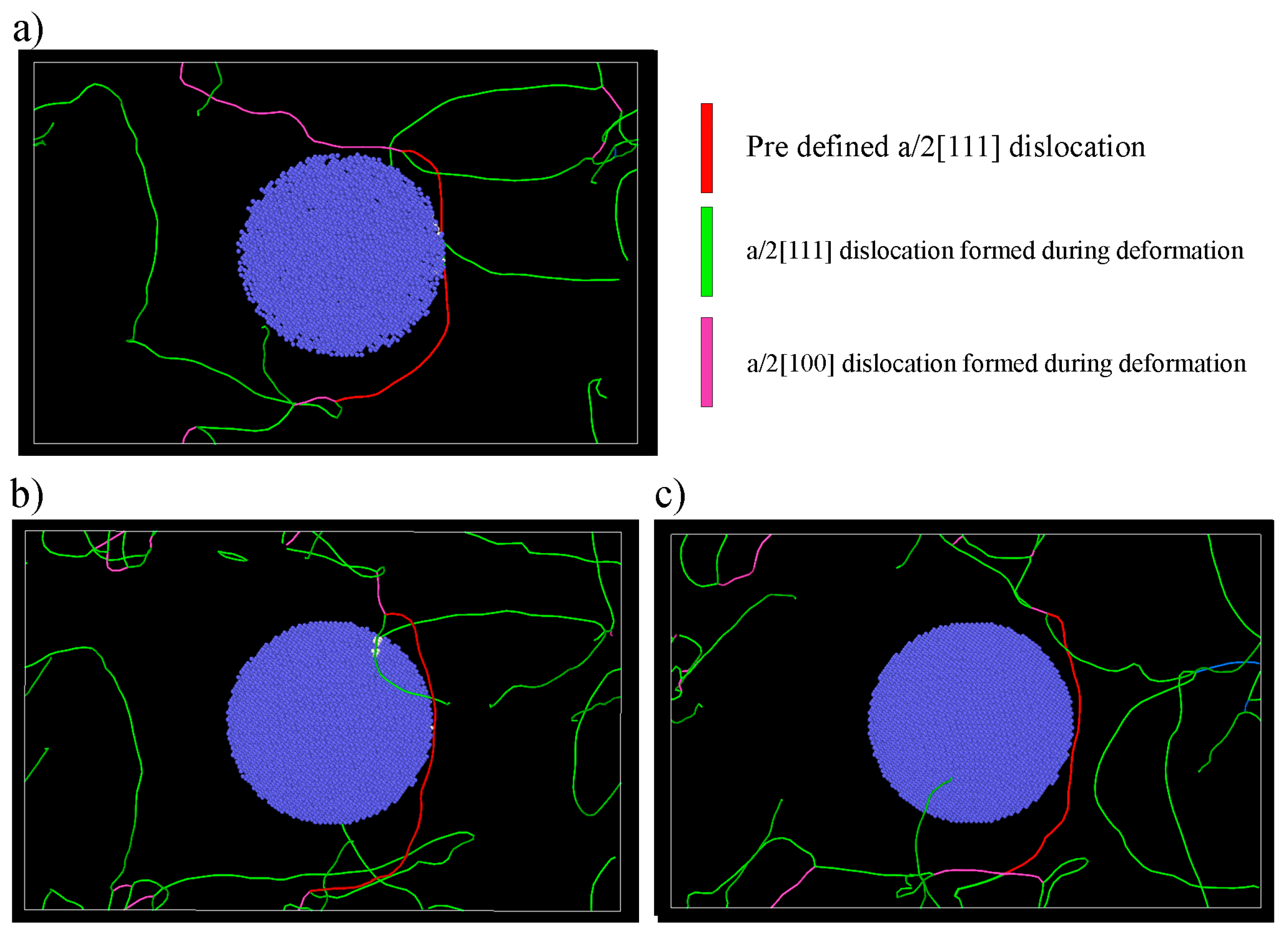
3.1. Mechanism of the Interaction

Figure 3 shows images of the dislocations formed in the structure for all three precipitates at the initial timestep of the simulation (20 ps). Through the application of stress, as well as the dislocation that was defined in our structure (shown in red), additional dislocations (shown in green and purple) are also formed throughout the cell. The formation of additional dislocations is primarily attributed to the stress applied to the system, and the inherent nature of dislocation dynamics in crystalline materials. When stress is exerted, local strain concentrations are created, resulting in the nucleation of new dislocations from existing defects or stress-induced deformation zones. These newly generated dislocations subsequently propagate through the crystal cell, and undergo interactions with one another, culminating in the formation of dislocation networks, and an overall increase in the dislocation density.
With the decrease in the vanadium concentration in the precipitate, the dislocation shape (the primary defined dislocation) changes from a long, straight line to a semicircle-like shape. In fact, this is due to the atomic packing effect. With the decrease in the vanadium concentration in the precipitate, the number of defined iron atoms outside the precipitate (in the matrix) will be considerably higher, because the same number of iron atoms is defined for all the simulation boxes. Having a higher atomic packing factor results in easier slip planes, which lead to the distribution of the non-uniform shear stress on the dislocation, and reduces the dislocation energy. Thus, the dislocation bows out [36]. It is worth mentioning that, in all cases, the dislocation asymmetric structure concerning the X axis implies the elastic anisotropy of the a/2[111] dislocations in the Fe-V system [37].
Figure 4 shows the dislocation/precipitate interaction when dislocation reaches the precipitate. In the case of the Fe-V (3:1) precipitate, the dislocation shape does not show any changes or bowing effect toward the direction of the applied force, which implies that there is no strong repulsive force from the precipitate to overcome the movement of the dislocation. This behavior in the dislocation line is similar to the void-and-dislocation interaction [38]. However, with the increase in the vanadium concentration in the precipitate, the dislocation slightly bends toward the opposite direction to the applied shear stress. This effect is more pronounced in the Fe-V (0:1) precipitate, where the repulsive force between the dislocation and precipitate causes the dislocation line to bow out at the areas that do not interact with the precipitate. This is due an increase in the energy of the dislocation line, as a result of the strong interaction between the dislocation and precipitate, leading to bowing out, to bring the dislocation line energy level back to the equilibrium state [39].
The simulation images obtained after the dislocation overtakes the precipitate are shown in Figure 5. The results clearly show that the dislocation overtakes the precipitate through the cutting process, and no evidence for the formation of the Orowan mechanism was obtained in any of the precipitates. Interestingly, no bowing effect was observed after the cutting process. It has been reported by researchers that the linear shape of the dislocation after cutting is due to the dislocation loop glide in collinear slip systems [40].

3.2. Dislocation Speed

Figure 6a–d show the results of the dislocation moving distance and moving speed versus time from the moment of dislocation nucleation until breakthrough on the surface. The time needed for the dislocation to reach the surfaces increases in the case of precipitates with a higher vanadium concentration (Figure 6a). It should be noted that the positions of dislocations at discrete time steps were recorded by the simulation. The dislocation velocities were calculated through analysis of the change in position of each dislocation between consecutive time steps, which involved the computation of the difference between the positions at time t+1 and time t for each dislocation. The dislocation velocity (Figure 6b–d) of each identified dislocation was then determined by dividing the change in position (displacement) by the corresponding time step. The average value of the dislocation speed was found to be 3.84, 2.52, and 1.88 Å/ps for the Fe-V (3:1), Fe-V (1:3), and Fe-V (0:1) precipitate, respectively. In the case of the Fe-V (3:1) precipitate, dislocations moved almost at a constant speed, even during the cutting process, which means there was no significant pinning effect of the precipitate. In the Fe-V (1:3) and Fe-V (0:1) precipitates, at the early stage of the deformation (20 ps), the dislocation speed rose rapidly. This is due to the bowing effect, which leads to a local accumulation of the flow stress at one point of the dislocation line, and increases the dislocation moving speed. The dislocation speed reaches the zero value for 8 ps and 10 ps in the Fe-V (1:3) and Fe-V (0:1) precipitate after the dislocation reaches the precipitate. Interestingly, after the cutting process, the dislocation speed increases rapidly, and declines until it reaches the zero value again, which is due to the formation of the junctions in the structure (shown in Figure 7). It is noteworthy to mention that all the dislocation speed values verify the theory of Eshelby, which indicates that the dislocation speed cannot exceed the speed of 14.5 Å/ps [41,42].
Figure 7 shows the dislocation algorithm analysis of the precipitates at the stage where the junctions are formed (after the cutting process). The dislocation interaction occurred between the a/2[111] (shown in red and green) and a/2[100] (shown in purple) dislocations. It is worth mentioning that the energy required for the movement of the a/2[100] dislocation is much higher than for that of the a/2[111], and it has been mentioned by some authors that, in some cases, this dislocation is immobile [43]. In the case of the Fe-V (3:1) precipitate, there is a junction that connects one big a/2[100] dislocation with two a/2[111] dislocations; however, it is not strong enough to prevent movement, and the dislocation bows out with a high radius. However, in the Fe-V (1:3) precipitate, the junction formed after the cutting process connects four a/2[111] dislocations with one a/2[100] dislocation (two each from one end). The dislocation bows out with a lower radius, which indicates the effectiveness of the junction in preventing the dislocation movement. Despite the fact, a high length of immobile a/2[100] dislocation was formed in the Fe-V (3:1) precipitate; compared to the Fe-V (1:3), the defined a/2[111] dislocation moved easily. This implies that the junction configuration is a more important factor in preventing the movement of the a/2[111] dislocation than the length of the immobile a/2[100] dislocation.
Interestingly, in the Fe-V (3:1) precipitate, a zig-zag chain configuration of the junctions (Figure 7d) is formed, which will make the dislocation’s motion and deformation more difficult. It is believed that the lower speed of the dislocation in the Fe-V (0:1) precipitate increases the possibility of the interaction of the a/2[100] with the a/2[111] dislocations in the structure, which would lead to the formation of more complex junctions.

3.3. Stress–Time Curves

The stress–time curve result of the molecular dynamics simulation is shown in Figure 8. In all precipitates, the stress–time curves show a saw-tooth pattern and, when the vanadium concentration in the precipitate increases, this pattern becomes more pronounced. In fact, this behavior is due to the asymmetric stress distribution on the dislocation line during the deformation. During the early stage of the simulation, there is only a limited difference between the three defined systems; however, when the dislocations reach the precipitate, the value of the stress changes. In the Fe-V (3:1) precipitate, the stress remains steady, at the value of 350 MPa. In the case of the Fe-V (1:3) and Fe-V (0:1) precipitate, after the dislocation reaches the precipitate, the value of the stress rises sharply up to 700 and 900 MPa, respectively. This rapid rise in stress is followed by a sudden drop, which is known as critical depinning stress [44,45]. The simulation results indicate that the highest critical depinning stress belongs to the Fe-V (0:1) precipitate. With more time, the fluctuation in the stress value increases, which is due to the bonding and debonding of atoms when the junctions are formed.

3.4. Void Formation

The number of voids formed in all three systems during the simulation has been plotted in Figure 9. In the Fe-V (0:1) precipitate, the highest volume fraction of the voids formed during the deformation. Interestingly, after the dislocation reaches the precipitate and cuts the precipitate, the void volume fraction rises at a higher rate in the structure. On the other hand, the lowest volume fraction of voids was formed in the Fe-V (3:1) precipitate. Generally, due to the dislocation stress gradients, voids are attracted to the compressive strain regions of the dislocation, and are repelled by tensile regions [46]. The number of voids rises when the compressive regions in front of the dislocation line squeeze a large number of the atom clusters. Therefore, it can be concluded that the dislocation line in the Fe-V (0:1) precipitate has a higher compressive strain during the cutting process.
The theory of the formation of voids in BCC metals reports that, during the deformation of materials, stress concentrations form non-homogenously in the structure. These stress concentrations are responsible for the atoms’ local de-bonding, and the formation of voids. In the case of the alloys, these voids that are formed at the precipitate/matrix interface can increase the strength of the alloy, because dislocations have to create a surface step (in the direction of their Burgers vector) by shear, when cutting a void [47]. Therefore, it can be concluded that the formation of a high number of voids as a result of the increasing vanadium concentration in the precipitate can also account for the obtaining of a high level of shear stress.

3.5. Effect of Cutting on Precipitate Structure

To understand clearly how the dislocations cut through the precipitate, the radial distribution function (RDF) of the V-V atom pair on the precipitate was evaluated before and after the cutting process (Figure 10). The RDF results of the precipitate before the cutting process show well-defined crystallographic planes. However, after the cutting process, the intensity of the peaks decreased and slightly shifted to the higher distance, and no peak appeared at the long distance, which clearly indicates that the precipitate structure changes from crystalline to amorphous after the cutting process. The lower intensity of the peak in the Fe-V (3:1) precipitate shows that the degree of amorphization was higher in this precipitate. In fact, it can be said that with the increase in the vanadium ratio in the precipitate, the accumulation of elastic energy during the cutting process increases, which facilitates amorphization. The dislocation cuts the precipitate into two different parts, one lying above the (110) plane parallel to, and aligned, with the notch surface, and the other lying below; the separation of the atoms into these two parts creates atomic disorder. It is worth mentioning that, once the structure of the precipitate becomes amorphous, it becomes more vulnerable to further dislocation movement. As mentioned earlier, amorphous materials lack long-range order, and their atomic arrangement is more disordered. As a result, subsequent dislocations that encounter the amorphous precipitate can more easily cut through it, compared to the original crystalline precipitate. This can lead to further deformation, and contribute to the overall plasticity of the material.

4. Conclusions

In summary, molecular dynamics simulation using the LAMMPS code was carried out so we could understand the interaction mechanism between the a/2[111] dislocation and Fe-V precipitates with different vanadium concentrations. The following conclusions can be drawn as a result of this simulation:
  • With the increasing vanadium concentration in the precipitate, the dislocation slightly bends toward the opposite direction to the applied shear stress, as a result of the reduction in the energy level of the dislocation line, due to the strong interaction with the precipitate. However, at a low vanadium concentration (1:3 atomic ratio), the behavior of the dislocation line is similar to the void and dislocation interaction.
  • The dislocation overtakes all precipitate through cutting, and no Orowan loop is formed around the precipitate.
  • Increasing the vanadium concentration reduces the dislocation speed, and leads to the formation of multiple junctions between the a/2[111] and a/2[100] dislocation, and a high number of voids, which results in the alloy being strengthened.
  • The accumulation of elastic energy in the precipitate during the cutting process changes the structure from crystalline to amorphous, and the degree of amorphization decreases with the increasing vanadium concentration.

Author Contributions

S.Y.: conceptualization, investigation, methodology, software, writing—original draft preparation. M.M.: writing—review and editing, V.V.: conceptualization, validation, supervision, writing—review and editing. All authors have read and agreed to the published version of the manuscript.

Funding

One of the authors (Sepehr Yazdani) wishes to thank Belgian Fonds De La Recherche Scientifique—FNRS for the financial support in the framework of the Aspirant scholarship (FC 38373).

Data Availability Statement

The data that support the findings of this study are available from the corresponding author upon reasonable request.

Conflicts of Interest

The authors declare no conflict of interest.

References

  1. Chojcan, J. Interactions between V Atoms in Iron-Based Fe–V Solid Solutions. J. Alloys Compd. 2003, 350, 62–67. [Google Scholar] [CrossRef]
  2. Moskalyk, R.R.; Alfantazi, A.M. Processing of Vanadium: A Review. Miner. Eng. 2003, 16, 793–805. [Google Scholar] [CrossRef]
  3. Singh, A.P.; Pant, G. Mechanical Behaviour of Vanadium Microalloyed Steel under Control Environment Compression. Mater. Today Proc. 2020, 26, 2525–2527. [Google Scholar] [CrossRef]
  4. Xue, D.; Wei, W.; Shi, W.; Zhou, X.-R.; Wen, S.-P.; Wu, X.-L.; Gao, K.-Y.; Rong, L.; Qi, P.; Huang, H. Dislocation Evolution and Induced Precipitation on Corrosion Resistance of a Novel Al-Mg-Zn-Er-Zr Alloy during Hot Compression. Rare Met. 2023, 42, 2371–2380. [Google Scholar] [CrossRef]
  5. Fomin, E.V.; Mayer, A.E.; Krasnikov, V.S. Prediction of Shear Strength of Cluster-Strengthened Aluminum with Multi-Scale Approach Describing Transition from Cutting to Bypass of Precipitates by Dislocations. Int. J. Plast. 2021, 146, 103095. [Google Scholar] [CrossRef]
  6. Hu, Y.; Curtin, W.A. Modeling of Precipitate Strengthening with Near-Chemical Accuracy: Case Study of Al-6xxx Alloys. Acta Mater. 2022, 237, 118144. [Google Scholar] [CrossRef]
  7. Krasnikov, V.S.; Bezborodova, P.A.; Mayer, A.E. Effect of Hydrogen Accumulation on θ’precipitates on the Shear Strength of Al-Cu Alloys. Int. J. Plast. 2022, 159, 103475. [Google Scholar] [CrossRef]
  8. Khoei, A.R.; Youzi, M.; Eshlaghi, G.T. Mechanical Properties and γ/γ’interfacial Misfit Network Evolution: A Study towards the Creep Behavior of Ni-Based Single Crystal Superalloys. Mech. Mater. 2022, 171, 104368. [Google Scholar] [CrossRef]
  9. Huang, J.; Jiang, Y.; Jiang, F.; Xu, C. The Improved Mechanical Anisotropy of a Commercial Al–Cu–Mg–Mn–Si (2017) Aluminum Alloy by Cross Rolling. Adv. Eng. Mater. 2022, 24, 2100831. [Google Scholar] [CrossRef]
  10. Zhang, X.; Xiong, J.; Fan, H.; Zaiser, M. Microplasticity and Yielding in Crystals with Heterogeneous Dislocation Distribution. Model. Simul. Mater. Sci. Eng. 2019, 27, 74003. [Google Scholar] [CrossRef] [Green Version]
  11. Li, L.; Song, B.; Cai, Z.; Liu, Z.; Cui, X. Effect of Vanadium Content on Hydrogen Diffusion Behaviors and Hydrogen Induced Ductility Loss of X80 Pipeline Steel. Mater. Sci. Eng. A 2019, 742, 712–721. [Google Scholar] [CrossRef]
  12. Antillon, E.; Woodward, C.; Rao, S.I.; Akdim, B.; Parthasarathy, T.A. Chemical Short Range Order Strengthening in a Model FCC High Entropy Alloy. Acta Mater. 2020, 190, 29–42. [Google Scholar] [CrossRef]
  13. Wang, L.; Jin, J.; Cao, J.; Yang, P.; Peng, Q. Interaction of Edge Dislocations with Graphene Nanosheets in Graphene/Fe Composites. Crystals 2018, 8, 160. [Google Scholar] [CrossRef] [Green Version]
  14. Wu, X. Deformation and Evolution of Life in Crystalline Materials: An Integrated Creep-Fatigue Theory; CRC Press: Boca Raton, FL, USA, 2019. [Google Scholar]
  15. Pascuet, M.I.; Martínez, E.; Monnet, G.; Malerba, L. Solute Effects on Edge Dislocation Pinning in Complex Alpha-Fe Alloys. J. Nucl. Mater. 2017, 494, 311–321. [Google Scholar] [CrossRef] [Green Version]
  16. Terentyev, D.; Bonny, G.; Domain, C.; Monnet, G.; Malerba, L. Mechanisms of Radiation Strengthening in Fe–Cr Alloys as Revealed by Atomistic Studies. J. Nucl. Mater. 2013, 442, 470–485. [Google Scholar] [CrossRef]
  17. Wu, X.; Wang, X.; Wang, Y.; Liu, W.; Shu, G.; Li, C.; Li, Q.; Xu, B. Softening Effects Due to Reorientations of Cu Precipitates in α-Iron: Atomistic Simulations of Dislocations-Obstacles Interactions. J. Appl. Phys. 2019, 125, 195102. [Google Scholar] [CrossRef]
  18. Singh, C.V.; Warner, D.H. Mechanisms of Guinier–Preston Zone Hardening in the Athermal Limit. Acta Mater. 2010, 58, 5797–5805. [Google Scholar] [CrossRef]
  19. Mock, M.; Albe, K. Modelling of Dislocation-Solute Interaction in ODS Steels: Analytic Bond-Order Potential for the Iron-Yttrium System. J. Nucl. Mater. 2018, 509, 102–113. [Google Scholar] [CrossRef]
  20. Kiani, M.T.; Wang, Y.; Bertin, N.; Cai, W.; Gu, X.W. Strengthening Mechanism of a Single Precipitate in a Metallic Nanocube. Nano Lett. 2018, 19, 255–260. [Google Scholar] [CrossRef]
  21. Esteban-Manzanares, G.; Ma, A.; Papadimitriou, I.; Martínez, E.; LLorca, J. Basal Dislocation/Precipitate Interactions in Mg–Al Alloys: An Atomistic Investigation. Model. Simul. Mater. Sci. Eng. 2019, 27, 75003. [Google Scholar] [CrossRef] [Green Version]
  22. Dai, Q.-L.; Li, K.; Meng, K.-R.; Fang, Z.; Chen, W.; Yang, T.-B.; Feng, C.; Wu, J.-M.; Misra, R.D.K. Effect of Vanadium on the Microstructure and Mechanical Properties of 2100 MPa Ultra-High Strength High Plasticity Spring Steel Processed by a Novel Online Rapid-Induction Heat Treatment. Met. Mater. Int. 2023, 29, 922–933. [Google Scholar] [CrossRef]
  23. Wang, P.; Li, Z.; Lin, G.; Zhou, S.; Yang, C.; Yong, Q. Influence of Vanadium on the Microstructure and Mechanical Properties of Medium-Carbon Steels for Wheels. Metals 2018, 8, 978. [Google Scholar] [CrossRef]
  24. Zhao, P.; Wu, J.; Chen, H.; Liu, H.; Li, D.; Tan, J. Molecular Dynamics Simulation Study of Interaction Mechanism between Grain Boundaries and Subgrain Boundaries in Nano-Cutting. J. Manuf. Process. 2021, 67, 418–426. [Google Scholar] [CrossRef]
  25. Liu, H.; Zhao, P.; Guo, Y.; Li, D.; Wang, Y.; Sun, S.; Wu, J. Material Removal Behaviors of FCC Metals in Nanoscale and Microscale Scratching: Theoretical Model and Experiments. J. Mater. Process. Technol. 2023, 312, 117855. [Google Scholar] [CrossRef]
  26. Sharma, A.; Datta, D.; Balasubramaniam, R. Molecular Dynamics Simulation to Investigate the Orientation Effects on Nanoscale Cutting of Single Crystal Copper. Comput. Mater. Sci. 2018, 153, 241–250. [Google Scholar] [CrossRef]
  27. Rotondi, S.M.C.; Ailuno, G.; Mattioli, S.L.; Pesce, A.; Cavalleri, O.; Canepa, P. Morphological Investigation of Protein Crystals by Atomic Force Microscopy. Crystals 2023, 13, 1149. [Google Scholar] [CrossRef]
  28. Liang, L.; Li, S.; Chai, P.; Lan, K.; Yu, R. Molecular Dynamics Simulation of Single-Crystal 4H-SiC Nano Scratching with Different Scratching Directions of the Tool. Crystals 2023, 13, 1044. [Google Scholar] [CrossRef]
  29. Tafelmeier, S.; Hiebler, S. Molecular Dynamics Simulation of the Crystallization Behavior of Octadecane on a Homogeneous Nucleus. Crystals 2022, 12, 987. [Google Scholar] [CrossRef]
  30. Yazdani, S.; Vitry, V. Using Molecular Dynamic Simulation to Understand the Deformation Mechanism in Cu, Ni, and Equimolar Cu-Ni Polycrystalline Alloys. Alloys 2023, 2, 77–88. [Google Scholar] [CrossRef]
  31. Mendelev, M.I.; Han, S.; Son, W.; Ackland, G.J.; Srolovitz, D.J. Simulation of the Interaction between Fe Impurities and Point Defects in V. Phys. Rev. B 2007, 76, 214105. [Google Scholar] [CrossRef] [Green Version]
  32. Tadmor, E.B.; Miller, R.E. Modeling Materials: Continuum, Atomistic and Multiscale Techniques; Cambridge University Press: Cambridge, UK, 2011. [Google Scholar]
  33. Stukowski, A. Visualization and Analysis of Atomistic Simulation Data with OVITO–the Open Visualization Tool. Model. Simul. Mater. Sci. Eng. 2009, 18, 15012. [Google Scholar] [CrossRef]
  34. Kelchner, C.L.; Plimpton, S.J.; Hamilton, J.C. Dislocation Nucleation and Defect Structure during Surface Indentation. Phys. Rev. B 1998, 58, 11085. [Google Scholar] [CrossRef]
  35. Stukowski, A.; Bulatov, V.V.; Arsenlis, A. Automated Identification and Indexing of Dislocations in Crystal Interfaces. Model. Simul. Mater. Sci. Eng. 2012, 20, 85007. [Google Scholar] [CrossRef]
  36. Wirth, B.D.; Odette, G.R.; Maroudas, D.; Lucas, G.E. Dislocation Loop Structure, Energy and Mobility of Self-Interstitial Atom Clusters in Bcc Iron. J. Nucl. Mater. 2000, 276, 33–40. [Google Scholar] [CrossRef]
  37. Dezerald, L.; Rodney, D.; Clouet, E.; Ventelon, L.; Willaime, F. Plastic Anisotropy and Dislocation Trajectory in BCC Metals. Nat. Commun. 2016, 7, 11695. [Google Scholar] [CrossRef] [Green Version]
  38. Hayakawa, S.; Doihara, K.; Okita, T.; Itakura, M.; Aichi, M.; Suzuki, K. Screw Dislocation–Spherical Void Interactions in Fcc Metals and Their Dependence on Stacking Fault Energy. J. Mater. Sci. 2019, 54, 11509–11525. [Google Scholar] [CrossRef]
  39. Antillon, E.; Woodward, C.; Rao, S.I.; Akdim, B.; Parthasarathy, T.A. A Molecular Dynamics Technique for Determining Energy Landscapes as a Dislocation Percolates through a Field of Solutes. Acta Mater. 2019, 166, 658–676. [Google Scholar] [CrossRef]
  40. Kubin, L.P.; Madec, R.; Devincre, B. Dislocation Intersections and Reactions in FCC and BCC Crystals. MRS Online Proc. Libr. (OPL) 2003, 779. [Google Scholar] [CrossRef] [Green Version]
  41. Gurrutxaga–Lerma, B.; Verschueren, J.; Sutton, A.P.; Dini, D. The Mechanics and Physics of High-Speed Dislocations: A Critical Review. Int. Mater. Rev. 2021, 66, 215–255. [Google Scholar] [CrossRef]
  42. Bao, Q.; Huang, M.; Zhu, Y.; Zhao, L.; Li, Z. Abnormal Interactions between High-Speed Edge Dislocation and Microvoid in BCC Metals. Int. J. Plast. 2022, 148, 103125. [Google Scholar] [CrossRef]
  43. Gao, N.; Yao, Z.W.; Lu, G.H.; Deng, H.Q.; Gao, F. Mechanisms For< 100> Interstitial Dislocation Loops to Diffuse in BCC Iron. Nat. Commun. 2021, 12, 225. [Google Scholar] [PubMed]
  44. Azeem, M.M.; Wang, Q.; Li, Z.; Zhang, Y. Dislocation-Oxide Interaction in Y2O3 Embedded Fe: A Molecular Dynamics Simulation Study. Nucl. Eng. Technol. 2020, 52, 337–343. [Google Scholar] [CrossRef]
  45. Ibrahim, S.A.; Wang, Q.; Zhang, Y.; Ado, M.; Chung, G.D.; Azeem, M.M. Molecular Dynamics Simulation of Strengthening Dependence on Precipitate Cr Composition in Fe-15at.% Cr Alloy. Micron 2020, 131, 102823. [Google Scholar] [CrossRef]
  46. Hafez Haghighat, S.M.; Schäublin, R. Influence of the Stress Field Due to Pressurized Nanometric He Bubbles on the Mobility of an Edge Dislocation in Iron. Philos. Mag. 2010, 90, 1075–1100. [Google Scholar] [CrossRef]
  47. Osetsky, Y.N.; Bacon, D.J. Atomic-Scale Mechanisms of Void Hardening in Bcc and Fcc Metals. Philos. Mag. 2010, 90, 945–961. [Google Scholar] [CrossRef]
Figure 1. Schematic of the defined simulation box for monitoring the interaction of the a/2[111] dislocation (shown in green) with the precipitate (shown in blue).
Crystals 13 01247 g001
Figure 2. Two-dimensional view (Y-Z axis) of the simulation box for the (a) Fe-V (3:1), (b) Fe-V (1:3), and (c) Fe-V (0:1) defined precipitate. The vanadium atoms are shown in blue, and the iron atoms are shown in red.
Crystals 13 01247 g002
Figure 3. Dislocation algorithm analysis at 20 ps for the (a) Fe-V (3:1), (b) Fe-V (1:3), and (c) Fe-V (0:1) precipitate. The red color shows the pre-defined dislocation that was created in the simulation cell, and the green color and purple color show the dislocations formed due to the applied stress during the simulation.
Crystals 13 01247 g003
Figure 4. Dislocation algorithm analysis when our pre-defined dislocation (shown in red) reaches the (a) Fe-V (3:1), (b) Fe-V (1:3), and (c) Fe-V (0:1) precipitate.
Crystals 13 01247 g004
Figure 5. Dislocation algorithm analysis after our pre-defined dislocation (shown in red) cut through the (a) Fe-V (3:1), (b) Fe-V (1:3), and (c) Fe-V (0:1) precipitate.
Crystals 13 01247 g005
Figure 6. (a) The dislocation moving distance versus time, and the dislocation speed in the (b) Fe-V (3:1), (c) Fe-V (1:3), and (d) Fe-V (0:1) precipitate during the whole simulation process.
Crystals 13 01247 g006
Figure 7. The dislocation algorithm for the (a) Fe-V (3:1), (b) Fe-V (1:3), (c) Fe-V (0:1) precipitate, showing the junction formation between our pre-defined a/2[111] dislocation, and the a/2[111] (in green) and a/2[100] (in purple) dislocations, which formed due to the applied stress, and (d) the high resolution snapshot of the formed junctions.
Crystals 13 01247 g007
Figure 8. Variation in the shear stress versus time during the dislocation movement in the cell.
Crystals 13 01247 g008
Figure 9. Volume fraction of the voids as a function of the simulation time during the movement of the dislocation in the cell.
Crystals 13 01247 g009
Figure 10. The radial distribution function of V-V atom pairs in the precipitate before the cutting process (with the dash line), and after the cutting process (with single lines).
Crystals 13 01247 g010
Table 1. Details of the number of atoms for the simulation box.
Precipitate NameNumber of Vanadium Atoms in the PrecipitateNumber of Iron Atoms in the PrecipitateTotal Number of Atoms in the CellTotal Number of Atoms in the Precipitate
Fe-V (3:1)11,20033,594774,96044,794
Fe-V (1:3)33,66611,128774,96044,794
Fe-V (0:1)44,7940774,96044,794
Disclaimer/Publisher’s Note: The statements, opinions and data contained in all publications are solely those of the individual author(s) and contributor(s) and not of MDPI and/or the editor(s). MDPI and/or the editor(s) disclaim responsibility for any injury to people or property resulting from any ideas, methods, instructions or products referred to in the content.

