Article

Crystal Structure and Microwave Dielectric Property of xMgO-SiO2 (x = 1~2) System for 5G Applications

1
College of Electronics and Information, Hangzhou Dianzi University, Hangzhou 310018, China
2
Center for Electron Microscopy, State Key Laboratory Breeding Base of Green Chemistry Synthesis Technology, Zhejiang University of Technology, Hangzhou 310014, China
3
Department of Materials Science and Engineering, School of Engineering, Meybod University, Yazd 89616-99557, Iran
4
Institute of Communication Materials, Zhejiang Wazam New Materials Co., Ltd., Hangzhou 311121, China
5
School of Materials Science and Engineering, Qilu University of Technology (Shandong Academy of Sciences), Jinan 250353, China
6
Department of Materials Science and Engineering, Tarbiat Modares University, Tehran 14115-143, Iran
7
School of Instrumentation Science and Engineering, Harbin Institute of Technology, Harbin 150080, China
*
Authors to whom correspondence should be addressed.
These authors contributed equally to this work.
Crystals 2023, 13(9), 1296; https://doi.org/10.3390/cryst13091296
Submission received: 6 July 2023 / Revised: 11 August 2023 / Accepted: 21 August 2023 / Published: 23 August 2023
(This article belongs to the Section Polycrystalline Ceramics)

Abstract

:
Mg2SiO4 and MgSiO3 ceramics with superior microwave dielectric properties are considered to be promising candidates for 5G applications. However, a slight deviation from the stoichiometric Mg/Si ratio will significantly influence their microwave dielectric properties, which will hinder their practical applications. In this work, the xMgO-SiO2 (x = 1~2) ceramics were synthesized by a solid-state reaction method. The influence of the Mg/Si ratio x on the crystalline phase, microstructure, and microwave dielectric properties was investigated through X-ray diffraction (XRD), a scanning electron microscope (SEM), and the resonant cavity method. The XRD patterns revealed the coexistence of Mg2SiO4 and MgSiO3 within the x range of 1~2, which was further demonstrated by the energy-dispersive X-ray spectra. The SEM images show a typical polycrystalline morphology of ceramics with an inhomogeneous grain size distribution. It is found that the microwave dielectric properties fluctuate at both sides of the x range while those remain relatively stable with minor changes at the intermediate components, indicating an obvious low composition dependence helpful for practical applications. Further, a demonstrator of a microstrip patch antenna for 5G applications using the 1.5MgO-SiO2 ceramic was designed and fabricated, and a return loss of −16.2 dB was demonstrated, which demonstrated the potential applications.

1. Introduction

In recent years, 5G communication applications have demonstrated tremendous potential owing to their low latency and high-speed capabilities [1,2]. With the continuous advancement of higher frequencies, faster speeds, and reduced power consumption, these applications have a brilliant future in various fields such as the Internet of Things (IoT), intelligent transport systems (ITS), and cloud computing. As a critical dielectric component in 5G communication, microwave dielectric ceramics (MWDCs) play a vital role in the form of dielectric antennas, filters, resonators, substrates, and more [3,4,5]. To meet the increasing performance demands, MWDCs must possess a relatively low dielectric constant and low dielectric loss. Additionally, for practical applications and large-scale production, it is essential to consider factors such as the cost effectiveness, ease of manufacturing, and consistent reliability of MWDCs.
Considering the aforementioned factors, there has been extensive research on low-cost MWDCs with low dielectric constants, particularly those below 10, due to their significant relevance. For instance, cordierite ceramics with a dielectric constant around 6 have gained much attention. However, their composition is complex. It is challenging to control the phase transition between cordierite and indialite. Therefore, the presence of the secondary phase always affects the dielectric loss, and the Q × f value usually remains relatively low, at less than approximately 40,000 GHz [6,7]. Another example is alumina (Al2O3) ceramics with a dielectric constant of 10, exhibiting exceptionally low dielectric loss and a Q × f value that can exceed 300,000 GHz [8,9]. However, a prolonged high-temperature sintering is necessary to obtain dense ceramics [10,11]. Similarly, MgO microwave dielectric ceramics also require a high sintering temperature with a prolonged sintering time above 1500 °C, though they have an ultrahigh Q × f value exceeding 200,000 GHz with a dielectric constant of approximately 9~10 [12,13]. On the other hand, SiO2 has a low dielectric constant, which can be as low as less than 4. It exhibits exceptionally ultralow dielectric loss with very high Q × f values of above 1,000,000 GHz in single-crystal form [14]. However, the preparation of ceramics is difficult and the Q × f value is quite low due to high sensitivity with sintering temperature and various accompanying defects, such as inhomogeneous microstructures originating from complex polymorphs and phase transformations [15]. Fang et al. have prepared cristobalite ceramics with a Q × f value of 80,000 GHz and a dielectric constant of 3.8 [16].
In the MgO-SiO2 binary system, Mg2SiO4 (Mg/Si = 2) has emerged as a promising microwave dielectric ceramic with a high Q × f value of up to 200,000 GHz and a low dielectric constant of about 7 [17,18,19]. However, there are fluctuations in the component near Mg/Si = 2 during the actual synthesis and preparation process, resulting in a small amount of the MgSiO3 (Mg/Si = 1) phase that deteriorates the Q × f value [20,21]. MgSiO3 ceramics synthesized by Song et al. also have good microwave dielectric properties of εr = 6.7 and Q × f = 121,200 GHz [22]. Nevertheless, Mg2SiO4 usually appears at the stochiometric ratio (Mg/Si = 1), which can also cause fluctuations in microwave dielectric properties [19]. On the other hand, Yeon et al. achieved a coexistence of Mg2SiO4 and MgO in a multi-phase ceramic by varying the Mg/Si ratio (2~5) [23]. Inspired by the above consideration, in order to find the composition interval with stable properties, there is potential to achieve MgSiO3-Mg2SiO4 coexisting ceramics in the MgO-SiO2 system by adjusting the Mg/Si ratio in the range of 1~2, which would reduce the sensitivity to composition during the ceramic preparation process to facilitate practical applications.
In this paper, xMgO-SiO2 (x = 1~2) ceramics were synthesized and prepared using a solid-state reaction method. The influence of the ratio x on the crystalline phase, microstructure and microwave dielectric property was investigated. Based on this, a demonstrator of microstrip patch antenna for 5G application using MgO-SiO2 system ceramics was designed, fabricated, and evaluated.

2. Materials and Methods

The xMgO-SiO2 (x = 1, 1.05, 1.2, 1.36, 1.5, 1.66, 1.8, 1.98, and 2) ceramics were synthesized and prepared by a solid-state reaction method. High-purity oxides (>99.9%, all from aladdin) of MgO and SiO2 were dried before use and weighed according to the different molar ratios of the compositions. The mixed raw material powder was ball-milled for 24 h in ethanol and then dried at 60 °C for 24 h. The dried powders were ground and calcined at 1150 °C for 3 h. After that, the calcined powders were ball-milled again. Subsequently, the dried powders were mixed with 8 wt% binder (polyvinyl alcohol, PVA) and pressed into green pellets at a pressure of 98 MPa. The pellets were firstly heated at 650 °C in atmosphere for 2 h to burn out the PVA, then sintered at 1375 °C~1425 °C for 3 h. The heating and cooling rates were set as 5 °C/min and 2 °C/min, respectively.
The densities of the sintered xMgO-SiO2 ceramics were measured by the Archimedes method. The phase structures of the ceramics were analyzed with an X-ray diffractometer (XRD, Bruker D2 Phaser, Bruker, Karlsruhe, Germany) using CuKα radiation in the 2θ range of 10–80° at a step of 0.02°. The microstructure and grain size characterization were carried out by scanning electron microscopy (SEM, Sigma Zeiss 300, Carl Zeiss, Jena, Germany). The dielectric constant (εr) and Q × f of the sintered ceramics were measured through a network analyzer (Keysight N5234B, Keysight Technologies, Santa Rosa, CA, USA) using a resonant cavity method, while the values of the temperature coefficient of resonant frequency (τf) were determined by the following formula:
τ f = f 2 f 1 f 1 × ( T 2 T 1 ) × 10 6 ( ppm / ° C )
where f1 and f2 are the resonant frequencies measured at 20 °C and 80 °C, respectively.
The design and simulation of the microstrip patch antenna prototype using xMgO-SiO2 ceramics were conducted by the Computer Simulation Technology (CST) software. The as-sintered dried xMgO-SiO2 ceramic powder was added with 10 wt% PVA and then pressed into a 4 mm thick sample in a 30 mm × 30 mm custom-made mold. The green body was sintered at 1400 °C for 5 h to obtain the ceramic substrate. With the help of the CST simulation, double-sided conductive copper foil was attached to the ceramic substrate. A Sub-Miniature version A (SMA) connector was also soldered onto the patch to connect the ground plane and surface electrode.

3. Results

Figure 1a,b exhibit the room-temperature X-ray diffraction patterns within the 2θ range of 10°~80° and the enlargement of 26°~34° for xMgO-SiO2 ceramics with various Mg/Si ratios. The pattern of x = 1 is composed of the peaks of major MgSiO3 (Protoenstatile, PEN, PDF#11-0273), minor MgSiO3 (Clinoenstatite, CEN, PDF#76-0526), and residual SiO2 (see Figure 1b). The existence of CEN could be related to the phase transition from PEN to CEN during the cooling process of ceramic sintering [24]. Actually, there is a very weak peak of Mg2SiO4 (Forsterite, PDF#85-1346) at about 32.3°. As x slightly increases to 1.05, the weak characteristic peaks of Mg2SiO4 appear near both 22.9° and 32.3°. Further, when x increases to 1.2, the peak of CEN almost disappears within the accuracy, which could be attributed to the decrease in PEN. Subsequently, the intensity of Mg2SiO4 peaks gradually increases while the intensity of PEN peaks decreases. This indicates that the content of Mg2SiO4 gradually increases with the increasing Mg/Si ratio, while the content of PEN decreases. Although the peak intensity of PEN has been weakening, the characteristic peaks of PEN are still observed when x = 2. A similar scenario also occurred in previous reports [20,21]. Meanwhile, the trace SiO2 always exists within the x range of 1~2. According to the study of Kazakos et al., the above phenomena demonstrate the incompleteness of the chemical reaction in the preparation process of xMgO-SiO2 ceramics [25]. Overall, the phase development of xMgO-SiO2 system ceramics essentially leads to the composite of MgSiO3 and Mg2SiO4. This may be related to two aspects. On the one hand, the diffusion rate of MgO and SiO2 is relatively slow during the reaction process, which results in the reaction process being affected by the degree of diffusion. On the other hand, the thermodynamic and kinetic factors of the reaction of MgSiO3 and Mg2SiO4 could be affected by local compositional fluctuations [25,26].
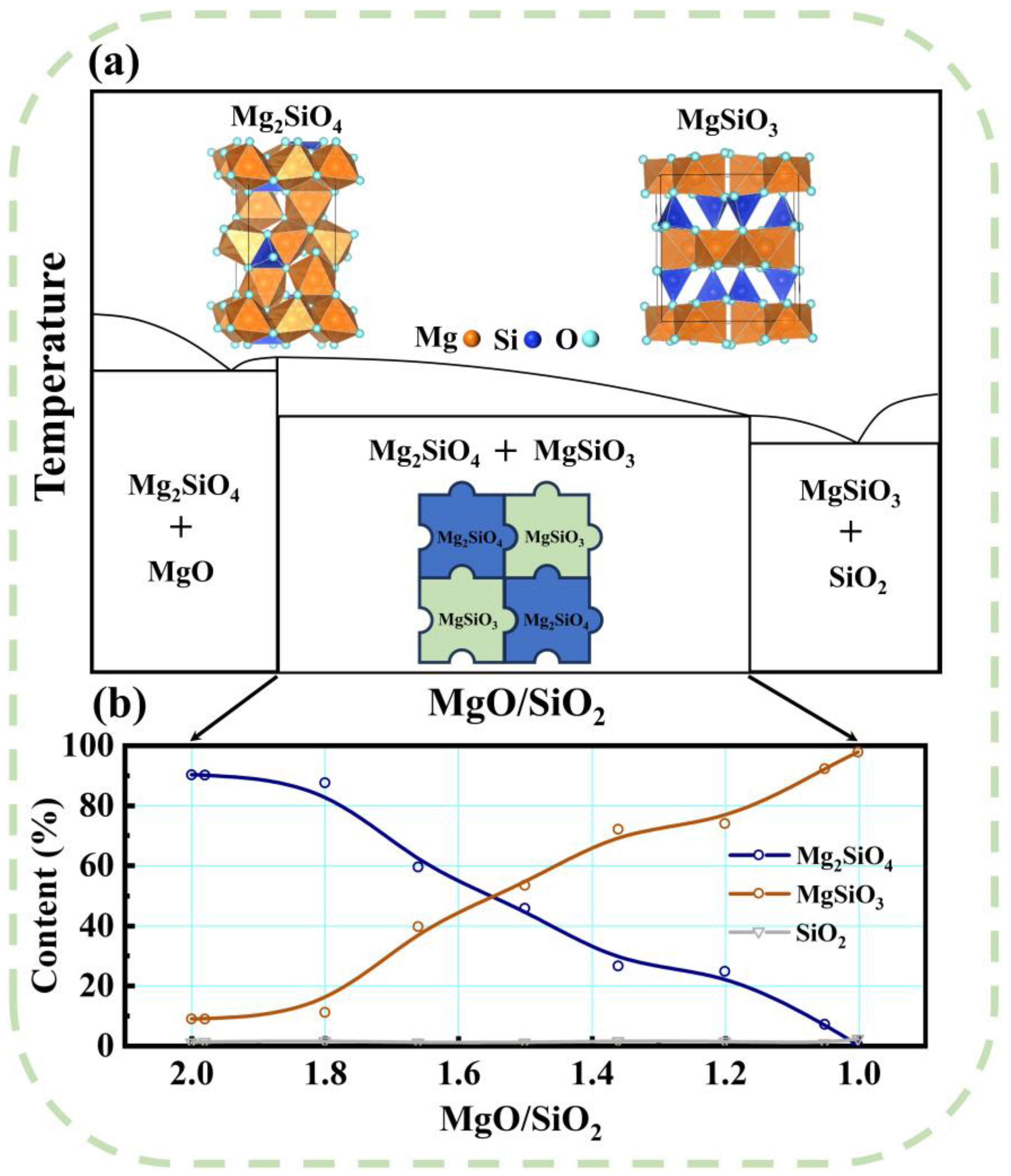
In order to gain a more intuitive understanding of the influence of Mg/Si on the phase composition of the system, Figure 2a,b depict the schematic diagram of the ideal case of a xMgO-SiO2 ceramic phase diagram and the semi-quantitative calculation results of the phase content. Generally speaking, when Mg/Si is less than 1, the phase composition is mainly composed of MgSiO3 and SiO2. When Mg/Si is larger than 2, Mg2SiO4 will be the major composition accompanied by excessive MgO [23]. As for Mg/Si within the range of 1~2, the phase compositions can be considered to be the coexistence of MgSiO3 and Mg2SiO4. To further analyze the phase composition, the semi-quantitative calculation results of the phase content are obtained from the X-ray diffraction patterns by the RIR (Ratio of Intensity Reference) of PDF data. It can be discovered that the contents of MgSiO3 and Mg2SiO4 exhibit a decreasing and increasing trend with an almost linear relationship as increasing x, though a trace of residual SiO2 also exists.
Figure 3 shows the curve of the relative density of the ceramics versus the sintering temperature. The sintering temperatures of microwave ceramics in MgO-SiO2 systems are generally between 1300 °C and 1500 °C. Herein, 1375 °C, 1400 °C, and 1425 °C were selected as sintering temperatures. It can be observed that the maximum relative densities for all samples were obtained at almost 1400 °C. Based on this, the subsequent experimental measurements were carried out on the samples sintered at 1400 °C.
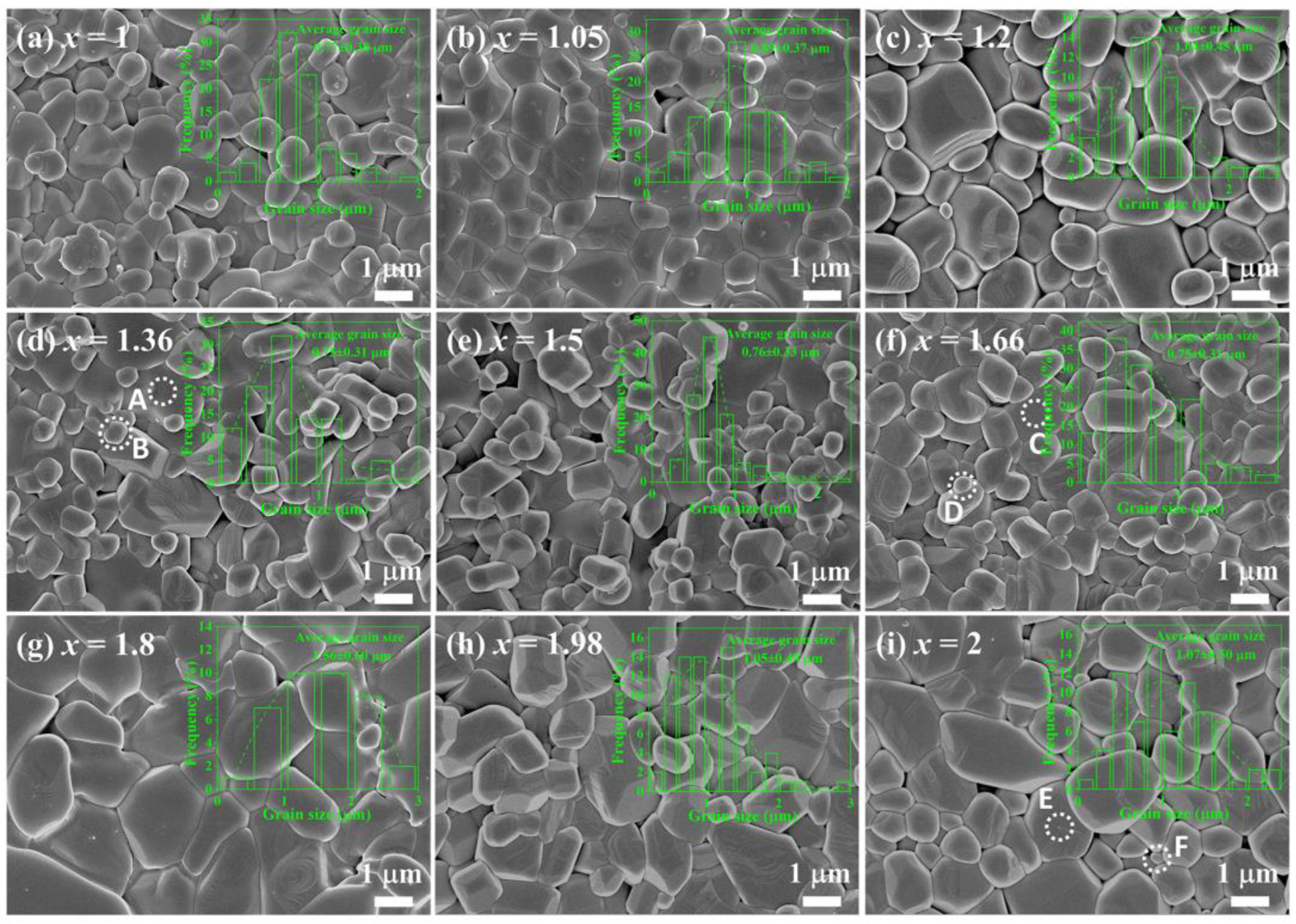
Figure 4a–i show the SEM images of xMgO-SiO2 (x = 1~2) as-sintered ceramics at 1400 °C. Though more or less pores can be observed for all the components, the SEM images show the typical polycrystalline morphology of ceramics with well grain crystalline. However, the grain size and shape vary. In order to analyze the variation in grain size with Mg/Si, the grain size of each component in the SEM images was calculated statistically. The statistical results of grain size are presented as insets in each figure, while the variation in average grain size with Mg/Si changing is shown in Figure 5a. It is observed that there is a significant variation in grain size at both ends of the range of x = 1~2. The average grain size increases from 0.77 mm at x = 1 to 1.04 mm at x = 1.2, while that decreases from 1.56 mm at x = 1.8 to 1.07 mm at x = 2. However, the average grain size and distribution at the intermediate components (x = 1.36, 1.5, and 1.66) keep quite close to each other, which could be ascribed to the coexistence of two phases of MgSiO3 and Mg2SiO4 with comparable contents. In addition, the large average grain size at x = 1.8 should be related to the involvement of the liquid phase with the residual traces, which can be observed with some bending morphological features at the grain boundary in Figure 4g. This leads to irregular grain growth in local areas, which is detrimental to the densification of ceramics [27,28].
For further analyzing the coexistence of MgSiO3 and Mg2SiO4 in xMgO-SiO2 ceramics, EDS were collected from the selected areas of some representative components (see Figure 5b–g). At x = 1.36, the two circled areas of A and B were selected to analyze the element composition. It is observed that there are five peaks referring to C, O, Mg, Si, and Pt, respectively, in the EDS patterns for area A. The C signal comes from the background of the sample, while the Pt signal comes from the surface coating of the sample. The contents of elements O, Mg, and Si are shown in the figure. The Mg/Si ratio is calculated to be approximately 0.95, indicating that it should be MgSiO3. For area B, the Mg/Si ratio is obtained as being about 1.19, indicating that it should contain both MgSiO3 and Mg2SiO4. At x = 1.66, the analysis results of areas C and D from the EDS signals show that the Mg/Si ratios are 1.6 and 1.49, respectively, which are close to the nominal x value of 1.66. It also indicates the presence of both MgSiO3 and Mg2SiO4 phases. For both areas E and F at x = 2, the Mg/Si ratios increase to 1.79 and 1.49, respectively, indicating that Mg2SiO4 should be the main phase with a small amount of MgSiO3 as the minor phase. The above results are consistent with the previous XRD results.
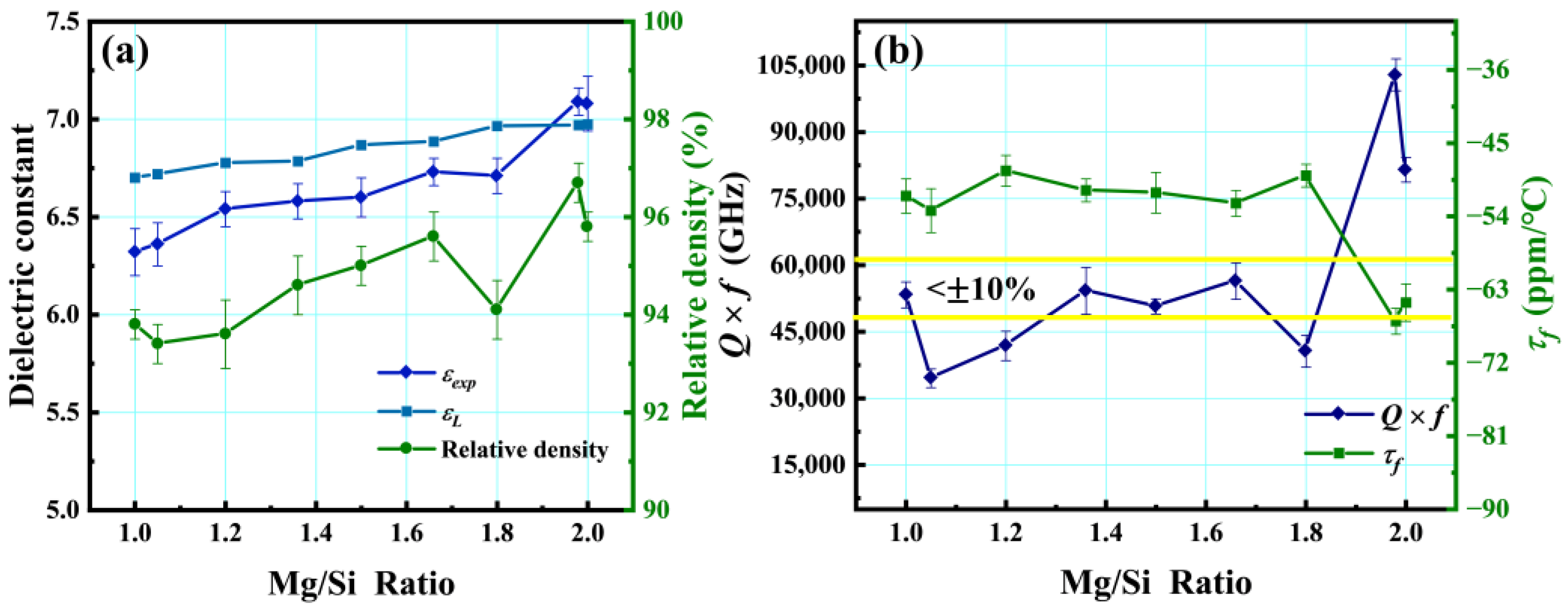
The dielectric constant and relative density with various Mg/Si ratios of the xMgO-SiO2 ceramics are plotted in Figure 6a, where εL and εexp are the theoretical dielectric constant and the experimental data. In general, the dielectric constant of ceramics is determined by numerous factors such as ion polarizability, phase composition, porosity, etc. Herein, according to the results of XRD and EDS analyses, xMgO-SiO2 (x = 1~2) ceramics can be considered as composites with the coexistence of Mg2SiO4 and MgSiO3. In this case, the theoretical dielectric constant εL of the composite can be calculated by the Lichteneker mixing rule [29], given as
ln ε L = i = 1 n V i ε i
where n is the number of phases and Vi and εi are divided into the volume fraction and dielectric constant of the i-th phase. As can be seen from Figure 6a, the calculated εL value increases monotonically, which can be attributed to the larger dielectric constant of Mg2SiO4 (εr~7) than MgSiO3 (εr~6.7). On the other hand, the values of εexp also increase monotonically as the Mg/Si ratio increases. However, the trend of εL has a deviation from the εexp value, which may imply that the influence of phase composition on the dielectric constant is not dominant in xMgO-SiO2 ceramics. In addition, the variation in relative density with various Mg/Si ratios is also plotted in Figure 6a. With an increasing Mg/Si ratio, the relative density basically shows a monotonic increasing trend with an exception at x = 1.8, where a significant decrease occurs relating to the involvement of the liquid phase. Interestingly, the trend of relative density is somewhat similar to the experimental data εexp, suggesting the decisive role of porosity in controlling the dielectric constant for xMgO-SiO2 ceramics.
Figure 6b records the Q × f and τf of the xMgO-SiO2 (x = 1~2) ceramics to evaluate the influence of Mg/Si ratios on microwave performance. The Q × f value reaches about 53,300 GHz at x = 1 and drops significantly to 34,500 GHz at x = 1.05. At the other end of the x range, the Q × f value increases from 40,600 GHz at x = 1.8 to a maximum of 102,900 GHz at x = 1.98 and then descends to 81,500 GHz at x = 2. Overall, the Q × f value fluctuates significantly at both ends of the x range. However, the Q × f values at the intermediate components of the x range (x = 1.36, 1.5, and 1.66) change little and remain basically between 50,000 and 60,000 GHz. Further, considering the deviation, it is calculated that the rate of change of Q × f is found to be less than ±10% when x is in the range of 1.36~1.66. Generally speaking, there are intrinsic and extrinsic factors that affect the Q × f value. The former are mainly related to the phonon system within the crystal, while the latter are related to many factors such as secondary phases, grain boundaries, dislocations, oxygen vacancies, inclusions, pores, etc. [30]. Here, the fluctuation at both ends may be mainly related to the inhomogeneous distribution of two phases of MgSiO3 and Mg2SiO4 and the fluctuation of the microstructure, while the relative stability of the Q × f values at the intermediate components should be related to the relatively homogeneous composition and microstructure of the two phases. The decrease in sensitivity of the Q × f value to components is beneficial for industrial production.
In addition, τf is also an important parameter for evaluating microwave performance. Similarly, τf remains relatively stable with less variation at intermediate components, while it fluctuates at both ends. In general, the τf value of a two-phase composite can be written as the following equation [31]:
τ f m i x = V 1 τ f 1 + V 2 τ f 2
where τfmix is the temperature coefficient of the resonant frequency of the two-phase composite and V1, V2 and τf1, τf2 are the volume fraction of each phase (here mainly MgSiO3 and Mg2SiO4) and the corresponding τf value, respectively. On the other hand, the τf value is also influenced by other factors such as crystal structure, microstructure, and porosity [32]. The final τf value is determined by a combination of multiple factors.
Considering the relatively stable performance at the intermediate components with low sensitivity, in order to evaluate the feasibility of practical applications, a microstrip patch antenna based on the 1.5MgO-SiO2 ceramic was simulated and fabricated. The initial dimensions of the patch were calculated based on Equations (4)–(7) and then adjusted according to the simulation results [33].
W p = c 2 f r 2 ε r + 1
L p = c 2 f r ε e f f 2 Δ L
ε e f f = ε r + 1 2 + ε r 1 2 1 + 12 h / W p
Δ L = 0.412 h ( ε e f f + 0.3 ) ( W p / h + 0.264 ) ( ε e f f 0.258 ) ( W p / h + 0.8 )
where c denotes the velocity of light in a vacuum, fr is the resonant frequency (7.08 GHz in this study), εeff and ΔL represent the effective dielectric constant and correction length, Wp and Lp are the width and length of the patch, and h is the thickness of the 1.5MgO-SiO2 ceramic substrate. Figure 7a displays the schematic image and the photograph of the antenna substrate and patch. The dimension of the fabricated 1.5MgO-SiO2 substrate is 28 mm × 28 mm × 1.3 mm. An ultrathin copper foil (thickness: ~0.06 mm) was adopted as the conducting electrode on both sides of the substrate. In addition, a 50 Ω SMA (Sub-Miniature version A) connector was assembled at the bottom of the antenna as the feeding. Figure 7b plots the measured and simulated S11 curves of the microstrip patch antenna, which represents the return loss characteristics and describes the ratio of incident power to reflected power (i.e., radiation efficiency) [34]. Herein, the profile of the measured S11 curve has a deviation from the simulated one. The resonant frequency of the measured results is 7.20 GHz with a bandwidth of 120 MHz, which is slightly larger than the simulated one (7.08 GHz and 102 MHz). The above phenomena can be ascribed to the size deviation during antenna handmaking and the ambient humidity of the test environment [35]. However, it is worth mentioning that the optimum value of S11 measured was −16.2 dB, which is obviously lower than −10 dB, indicating that more than 90% of the power is radiated through the antenna and demonstrating the commercial potential of the 1.5MgO-SiO2 microstrip patch antenna for 5G applications.

4. Conclusions

In this paper, xMgO-SiO2 (x = 1, 1.05, 1.2, 1.36, 1.5, 1.66, 1.8, 1.98, and 2) ceramics were synthesized and prepared by a solid-state reaction method. The XRD results show that the phase composition is mainly MgSiO3 and Mg2SiO4 with a trace residual SiO2. As x increases from 1 to 2, the content of MgSiO3 continues to decrease, while the amount of Mg2SiO4 continues to increase. The SEM images show that the grain size of ceramics is inhomogeneous with a significant variation in average grain size at both ends of the x range. The results of the EDS confirm that MgSiO3 and Mg2SiO4 coexist. The dielectric constant of xMgO-SiO2 ceramics is greatly influenced by the relative density. Both Q × f and τf values show a significant change at both ends of the x range, while they remain relatively stable with slight changes at the intermediate component. This may be related to the microstructure and two-phase constitution and distribution of ceramics. Finally, a microstrip patch antenna based on the 1.5MgO-SiO2 ceramic was designed and fabricated, demonstrating excellent performance to indicate its commercial potential in 5G applications.

Author Contributions

Y.W., J.L. and H.Z. contributed equally to this work. Y.W.: Formal Analysis, Investigation, Resources, Data Curation. J.L.: Formal Analysis, Investigation, Data Curation, Writing—Original Draft Preparation. H.Z.: Methodology, Validation, Data Curation, Writing—Original Draft Preparation, Visualization. Q.W.: Investigation, Resources, Data Curation. T.S.: Investigation, Resources, Data Curation. T.N.: Software, Resources. Y.L. (Yanghong Lin): Data Curation, Visualization. Y.L. (Yu Liu): Data Curation, Visualization. M.M.: Conceptualization, Methodology, Validation, Writing—Original Draft Preparation, Writing—Review and Editing, Supervision, Funding Acquisition. J.H.: Visualization. B.L.: Visualization. H.B.B.: Validation. Z.M.: Funding Acquisition. Y.R.: Funding Acquisition. F.S.: Validation. E.T.-N.: Validation. D.W.: Writing—Review and Editing. K.S.: Supervision, Project Administration, Funding Acquisition. All authors have read and agreed to the published version of the manuscript.

Funding

This work was supported by the National Natural Science Foundation of China (Grant Nos. 51602147, 52161145401, and 51672063), the Natural Science Foundation of Jiangsu Higher Education Institutions of China (16KJB430017), and the Department of Science and Technology of Zhejiang province on the “sharp soldiers” and “leading geese” research and development research planning project (No. 2023C01183).

Data Availability Statement

All data generated or analyzed during this study are included in this published article.

Conflicts of Interest

The authors declare that they have no conflict of interest.

References

  1. Dangi, R.; Lalwani, P.; Choudhary, G.; You, I.; Pau, G. Study and Investigation on 5G Technology: A Systematic Review. Sensors 2021, 22, 26. [Google Scholar] [CrossRef] [PubMed]
  2. Park, J.; Samarakoon, S.; Shiri, H.; Abdel-Aziz, M.K.; Nishio, T.; Elgabli, A.; Bennis, M. Extreme ultra-reliable and low-latency communication. Nat. Electron. 2022, 5, 133–141. [Google Scholar] [CrossRef]
  3. Shehbaz, M.; Du, C.; Zhou, D.; Xia, S.; Xu, Z. Recent progress in dielectric resonator antenna: Materials, designs, fabrications, and their performance. Appl. Phys. Rev. 2023, 10, 021303. [Google Scholar] [CrossRef]
  4. Krishna, V.N.; Padmasine, K.G. A review on microwave band pass filters: Materials and design optimization techniques for wireless communication systems. Mater. Sci. Semicond. Process. 2023, 154, 107181. [Google Scholar] [CrossRef]
  5. Kamutzki, F.; Schneider, S.; Barowski, J.; Gurlo, A.; Hanaor, D.A.H. Silicate dielectric ceramics for millimetre wave applications. J. Eur. Ceram. Soc. 2021, 41, 3879–3894. [Google Scholar] [CrossRef]
  6. Lou, W.; Mao, M.; Song, K.; Xu, K.; Liu, B.; Li, W.; Yang, B.; Qi, Z.; Zhao, J.; Sun, S.; et al. Low permittivity cordierite-based microwave dielectric ceramics for 5G/6G telecommunications. J. Eur. Ceram. Soc. 2022, 42, 2820–2826. [Google Scholar] [CrossRef]
  7. Ohsato, H.; Kagomiya, I.; Terada, M.; Kakimoto, K. Origin of improvement of Q based on high symmetry accompanying Si-Al disordering in cordierite millimeter-wave ceramics. J. Eur. Ceram. Soc. 2010, 30, 315–318. [Google Scholar] [CrossRef]
  8. Yuan, L.; Wang, H.; Lin, H.; Li, W.; Li, X.; Shi, J. Effect of MgO/La2O3 co-doping on the microstructure, transmittance and microwave dielectric properties of translucent polycrystalline alumina. Ceram. Int. 2014, 40, 2109–2113. [Google Scholar] [CrossRef]
  9. Zhang, K.; Yuan, L.; Fu, Y.; Yuan, C.; Li, W. Microwave dielectric properties of Al2O3 ceramics co-doped with MgO and Nb2O5. J. Mater. Sci. Mater. Electron. 2015, 26, 6526–6531. [Google Scholar] [CrossRef]
  10. Huang, C.-L.; Wang, J.-J.; Huang, C.-Y. Sintering behavior and microwave dielectric properties of nano alpha-alumina. Mater. Lett. 2005, 59, 3746–3749. [Google Scholar] [CrossRef]
  11. Alford, N.M.; Penn, S.J. Sintered alumina with low dielectric loss. J. Appl. Phys. 1996, 80, 5895–5898. [Google Scholar] [CrossRef]
  12. Mage, J.C.; Marcilhac, B.; Gerbaux, X.; Hadni, A. Microwaves properties of MgO single crystals computed from the IR, and measured with a resonator technique. Int. J. Infrared Millim. Waves 1994, 15, 1189–1203. [Google Scholar] [CrossRef]
  13. Liang, Z.; Li, J.; Wu, J.; Yang, Y.; Lu, B.; Zhang, Y.; Zhang, H. Enhanced microstructure and dielectric properties of low-temperature sintered MgO-xwt%LiF ceramics for high-frequency applications. Ceram. Int. 2022, 48, 2704–2709. [Google Scholar] [CrossRef]
  14. Krupka, J.; Derzakowski, K.; Tobar, M.; Hartnett, J.; Geyer, R.G. Complex permittivity of some ultralow loss dielectric crystals at cryogenic temperatures. Meas. Sci. Technol. 1999, 10, 387. [Google Scholar] [CrossRef]
  15. Hu, C.; Liu, P. Preparation and microwave dielectric properties of SiO2 ceramics by aqueous Sol–Gel technique. J. Alloys Compd. 2013, 559, 129–133. [Google Scholar] [CrossRef]
  16. Fang, Y.; Li, L.; Xiao, Q.; Chen, X.M. Preparation and microwave dielectric properties of cristobalite ceramics. Ceram. Int. 2012, 38, 4511–4515. [Google Scholar] [CrossRef]
  17. Ohsato, H.; Tsunooka, T.; Sugiyama, T.; Kakimoto, K.-i.; Ogawa, H. Forsterite ceramics for millimeterwave dielectrics. J. Electroceram. 2006, 17, 445–450. [Google Scholar] [CrossRef]
  18. Nurbaiti, U.; Darminto; Triwikantoro; Zainuri, M.; Pratapa, S. Synthesis and characterization of silica sand-derived nano-forsterite ceramics. Ceram. Int. 2018, 44, 5543–5549. [Google Scholar] [CrossRef]
  19. Ullah, A.; Liu, H.; Hao, H.; Iqbal, J.; Yao, Z.; Cao, M.; Xu, Q. Phase and Microstructure Evaluation and Microwave Dielectric Properties of Mg1−xNixSiO3 Ceramics. J. Electron. Mater. 2016, 45, 5133–5139. [Google Scholar] [CrossRef]
  20. Song, K.X.; Chen, X.M.; Fan, X.C. Effects of Mg/Si Ratio on Microwave Dielectric Characteristics of Forsterite Ceramics. J. Am. Ceram. Soc. 2007, 90, 1808–1811. [Google Scholar] [CrossRef]
  21. He, G.; Li, Z.; Dong, Y.; Wang, G. Effects of excessive magnesium oxide and sintering regime on microstructure and dielectric properties of forsterite ceramics for millimeterwave dielectrics. J. Mater. Sci. Mater. Electron. 2022, 33, 3129–3138. [Google Scholar] [CrossRef]
  22. Song, M.-E.; Kim, J.-S.; Joung, M.-R.; Nahm, S.; Kim, Y.-S.; Paik, J.-H.; Choi, B.-H. Synthesis and Microwave Dielectric Properties of MgSiO3 Ceramics. J. Am. Ceram. Soc. 2008, 91, 2747–2750. [Google Scholar] [CrossRef]
  23. Yeon, D.H.; Han, C.S.; Key, S.H.; Kim, H.E.; Cho, Y.S. Physical and Microwave Dielectric Properties of the MgO-SiO2 System. Korean J. Mater. Res. 2009, 19, 550–554. [Google Scholar] [CrossRef]
  24. Ohi, S.; Osako, T.; Miyake, A. Effects of Grain Size, Cooling Rate, and Sample Preparation on the Phase Transition from Protoenstatite to Clinoenstatite. Can. Mineral. 2022, 60, 405–416. [Google Scholar] [CrossRef]
  25. Kazakos, A.; Komarneni, S.; Roy, R. Preparation and Densification of Forsterite (Mg2SiO4) by Nanocomposite Sol-Gel Processi-ng. Mater. Lett. 1990, 9, 405–409. [Google Scholar] [CrossRef]
  26. Brindley, G.W.; Hayami, R. Kinetics and Mechanism of Formation of Forsterite (Mg2SiO4) by Solid State Reaction of MgO and SiO2. Philos. Mag. 1965, 12, 505–514. [Google Scholar] [CrossRef]
  27. Lai, Y.; Tang, X.; Zhang, H.; Liang, X.; Huang, X.; Li, Y.; Su, H. Correlation between structure and microwave dielectric properties of low-temperature-fired Mg2SiO4 ceramics. Mater. Res. Bull. 2018, 99, 496–502. [Google Scholar] [CrossRef]
  28. Zhang, L.; Cao, S.; Li, Y.; Jing, R.; Hu, Q.; Tian, Y.; Gu, R.; Kang, J.; Alikin, D.O.; Shur, V.Y.; et al. Achieving ultrahigh energy storage performance over a broad temperature range in (Bi0.5Na0.5)TiO3-based eco-friendly relaxor ferroelectric ceramics via multiple engineering processes. J. Alloys Compd. 2022, 896, 163139. [Google Scholar] [CrossRef]
  29. Wang, X.; Zhou, S.; Liu, K.; Deng, S.; Xiao, Y.; Chen, X.; Zhou, H. Broad sintering temperature range and stable microwave dielectric properties of Mg2TiO4-CeO2 composite ceramics. Ceram. Int. 2022, 48, 20245–20250. [Google Scholar] [CrossRef]
  30. Hameed, I.; Li, L.; Liu, X.Q.; Chen, X.M. Ultra low loss (Mg1−xCax)2SiO4 dielectric ceramics (x = 0 to 0.15) for millimeter wave applications. J. Am. Ceram. Soc. 2021, 105, 2010–2019. [Google Scholar] [CrossRef]
  31. Yan, X.; Liu, Y.; Tang, C.; Liu, S.; Ge, W.; Tong, J.; Meng, F. Microwave dielectric properties of Mg2SiO4-Ca1−ySm2y/3TiO3 composite ceramics. J. Mater. Sci. Mater. Electron. 2022, 33, 19751–19758. [Google Scholar] [CrossRef]
  32. Zhou, S.; Luan, X.; Hu, S.; Zhou, X.; He, S.; Wang, X.; Zhang, H.; Chen, X.; Zhou, H. Sintering behavior, phase structure and microwave dielectric properties of CeO2 added CaTiO3-SmAlO3 ceramics prepared by reaction sintering method. Ceram. Int. 2021, 47, 3741–3746. [Google Scholar] [CrossRef]
  33. Zhou, M.F.; Liu, B.; Hu, C.C.; Song, K.X. Ultra-low permittivity MgF2 ceramics with high Qf values and their role as microstrip patch antenna substrates. Ceram. Int. 2023, 49, 369–374. [Google Scholar] [CrossRef]
  34. Jin, D.H.; Liu, B.; Song, K.X.; Xu, K.W.; Huang, Y.H.; Hu, C.C.; Hu, Y.Y. Boosting densification and microwave dielectric properties in cold sintered BaF2 ceramics for 5.8 GHz WLAN applications. J. Alloys Compd. 2021, 886, 161141. [Google Scholar] [CrossRef]
  35. Xiang, H.; Kilpijärvi, J.; Myllymäki, S.; Yang, H.; Fang, L.; Jantunen, H. Spinel-olivine microwave dielectric ceramics with low sintering temperature and high quality factor for 5 GHz wi-fi antennas. Appl. Mater. Today 2020, 21, 100826. [Google Scholar] [CrossRef]
Figure 1. Room-temperature X-ray diffraction patterns of xMgO-SiO2 (x = 1~2) ceramics in the range of 2θ: (a) 10°–80°; (b) 26°–34°.
Crystals 13 01296 g001
Figure 2. (a) Schematic diagram of phase composition of xMgO-SiO2 ceramics; (b) semi-quantitative calculation results of the phase content of xMgO-SiO2 ceramics.
Crystals 13 01296 g002
Figure 3. The relative densities of xMgO-SiO2 (x = 1, 1.05, 1.2, 1.36, 1.5, 1.66, 1.8, 1.98, and 2) ceramics at different temperatures.
Crystals 13 01296 g003
Figure 4. SEM images of xMgO-SiO2 (x = 1~2) as-sintered ceramics at 1400 °C sintering temperature: (a) x = 1; (b) x = 1.05; (c) x = 1.2; (d) x = 1.36; (e) x = 1.5; (f) x = 1.66; (g) x = 1.8; (h) x = 1.98; (i) x = 2. The analytically calculated results of grain size for each component are inset. The energy-dispersive X-ray spectra (EDS) were collected from the dashed circled areas of A, B, C, D, E, and F.
Crystals 13 01296 g004
Figure 5. (a) The variation in average grain size with Mg/Si ratios; EDS and the analysis results of areas A (b), B (c) for x = 1.36, C (d), D (e) for x = 1.66, E (f), and F (g) for x = 1.66.
Crystals 13 01296 g005
Figure 6. (a) Dielectric constant and relative density of xMgO-SiO2-based ceramics as a function of Mg/Si ratio; (b) Q × f value and τf of xMgO-SiO2 ceramics as a function of Mg/Si ratio.
Crystals 13 01296 g006
Figure 7. (a) The schematic image and the photographs of antenna substrate and patch; (b) simulated and measured S11 of the microstrip patch antenna.
Crystals 13 01296 g007
Disclaimer/Publisher’s Note: The statements, opinions and data contained in all publications are solely those of the individual author(s) and contributor(s) and not of MDPI and/or the editor(s). MDPI and/or the editor(s) disclaim responsibility for any injury to people or property resulting from any ideas, methods, instructions or products referred to in the content.