Article

Robust Conveniently Sealable Container for High-Temperature Single-Crystal Growth Out of Reactive Melts with High Vapor Pressure

Lehrstuhl für Experimentalphysik IV, Fakultät für Physik und Astronomie, Ruhr-Universität Bochum, 44801 Bochum, Germany
*
Authors to whom correspondence should be addressed.
Current address: Experimentalphysik VI, Institut für Physik, Universität Augsburg, 86159 Augsburg, Germany.
Crystals 2023, 13(9), 1332; https://doi.org/10.3390/cryst13091332
Submission received: 7 August 2023 / Revised: 19 August 2023 / Accepted: 27 August 2023 / Published: 31 August 2023
(This article belongs to the Section Crystalline Metals and Alloys)

Abstract

:
The high-temperature crystal growth of intermetallics often asks for sealing of the materials in a protective atmosphere. Here, we report on the development of a convenient sealing method for alkali-containing melts, with high vapor pressure and reactivity. Our newly designed container made of high-temperature resistant steel can be sealed manually and reliably without any air exposure of the containing material. The closed container may be heated in air up to at least 1150 ° C. The containers were applied for the development and optimization of a high-temperature self-flux growth of KFe 1 x Ag 1 + y Ch 2 (Ch = Se, Te) single crystals. Their crystal structure and the low-temperature electrical resistance are presented. The successful growths of these air-sensitive materials out of a reactive self-flux confirm the reliability of the container.

1. Introduction

Single crystals are of vital importance for the measurement of material properties in solid-state research. A very accessible way to grow crystals of suitable size for most measurements is solution growth [1]. For this method, the constituent elements of the target material are dissolved in a flux by heating and crystals can form during subsequent cooling. During the growth process, the material has to be contained in a suitable container that does not react with any of the materials. After the crystal growth has taken place, it is desirable to separate the crystals from the remaining flux. This is easiest when the flux is still molten. One possibility is to stop cooling at sufficiently high temperature and decant the growth by centrifuging [2] whereby the molten flux can be separated from the crystals with the help of a sieve or quartz wool.
To keep the material in inert atmosphere during the growth and centrifuging at high temperatures, a container for the material is needed. The container has to be chosen such that the following requirements are fulfilled: First, the container should not react with any material. Second, the container has to be heat resistant up to the maximum temperature reached during the growth. Third, the container has to be small enough to fit into a centrifuge. Fourth, the container should close airtight to keep a protective atmosphere in its interior. Fifth, the container should sustain potential high pressure differences. Frequently, ampules of fused silica are used to seal crucibles for this purpose. However, fused silica cannot be used when working with alkali metals because alkali metal vapor reacts strongly with silica at high temperatures. Additionally, the alkali metals may lead to a high vapor pressure inside the container, which requires a more solid container. These problems are typically solved by using tantalum or tungsten containers [3]. Since tantalum and tungsten oxidize when heated in air [4], additional sealing in a protective atmosphere is required (frequently by fused silica ampules). Tantalum and tungsten containers have to be closed by welding in a protective atmosphere. This requires, e.g., an arc melter, leads locally to hot temperatures and is prone to error.
For faster and more reliable sealing of alkali-containing growths without the use of welding equipment, we developed an alternative approach, inspired by the method reported in ref. [5]. We have developed a container made from stainless steel which may be sealed manually inside an argon-filled glovebox, so that any containing material is not exposed to air. The use of specialized steel (EN 1.4841 [6]) allows to heat the assembly in a furnace in air without further protection. To test and prove the reliability of the container, it was used to grow KFe 1 x Ag 1 + y Ch 2 (Ch = Se, Te) single crystals from self-flux. In this article, we first report on the development, use and testing of the new steel container. We then describe the self-flux growth of KFe 1 x Ag 1 + y Ch 2 (Ch = Se, Te) with a detailed characterization regarding crystal structure, low-temperature resistance, occurrence of secondary phases and air-sensitivity of the obtained single crystals. These results underline the reliability and practicability of the container.

2. Materials and Methods

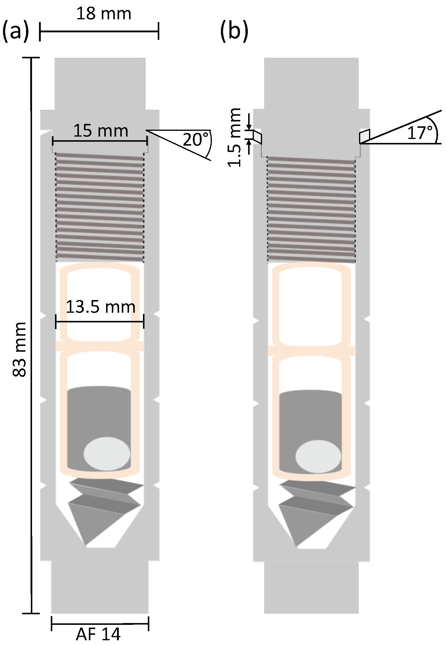
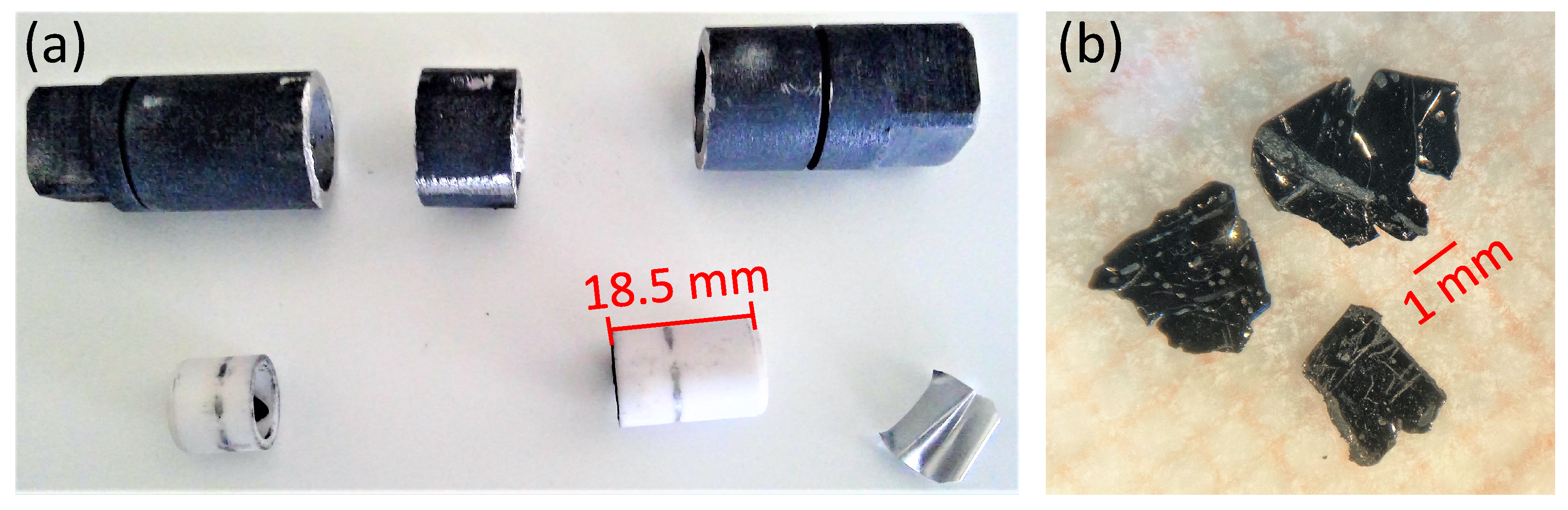
2.1. Novel Steel Container

The container developed for growth of alkali metal-containing compounds is of cylindrical shape and is closed with a screw cap on one side. It is sealed by deformation of a sealing ring between cap and main part. An overview of the container is presented in Figure 1. The container material is high-temperature resistant chromium-nickel steel EN 1.4841. The container has a total length of 83 m m , an outer diameter of 18 m m and an inner diameter of 13.5 m m and a mass of approximately 110 g. Above the M 15 × 1.5 6 g thread, the inner diameter extends to 15 m m . With this design, the container fits into a tube with 19 m m inner diameter.
Two versions of the container have been developed, one version with a separate sealing ring made of ARMCO ® pure iron and one version with the sealing ring integrated in the main container part. The separate iron sealing ring is 1.5 m m thick and has a 17 ° incline. Using this sealing ring proved to seal the container sufficiently and no signs of evaporation out of the container were detected.
In the version with integrated sealing ring, the upper edge of the main container part has a 20 ° incline such that the container wall is 0.5 m m higher at the inside than at the outside, so that no material other than the high-temperature resistant steel is used. To be able to achieve sufficient deformation of both sealing rings, the container is closed with the help of open-end wrenches. For this purpose, the top and the bottom end of the container have a quadratic cross section with rounded edges to fit in a 14 m m open-end wrench. The advantage of the separate iron sealing ring is that it is a lot easier to achieve a complete seal, as iron is softer than the chromium-nickel steel and can be deformed more easily. The advantage of the integrated sealing ring is that the entire container can be heated safely in air, see below.
A crucible can be placed inside the container. We used an alumina Canfield Crucible Set [7] [see Figure 1c]. To ensure a stable position of the crucibles inside the container, a steel spring is used to press the crucible set together and against the bottom of the cap. Here, we used a folded steel sheet with one triangular end which is inserted into the container below the crucibles [see Figure 2]. This significantly reduces any spill of the materials from the crucible.
The chromium-nickel steel EN 1.4841 was chosen as the container material. This steel is specified for use in air up to temperatures of 1150 ° C . However, the separate iron sealing ring oxidizes when it is heated in air. Therefore, the container version with integrated sealing ring can be safely used and heated in air, within the temperature limits of the steel, but this is not possible when the iron sealing ring is used. Figure 3c shows a container with iron sealing ring that was heated in air. The iron sealing ring is oxidized at the outside. However, it is not entirely oxidized. Hence, this version should be sealed additionally under protective atmosphere in a fused silica tube but shorter heating periods might work without. In this respect, handling of the container with integrated sealing ring is easier and faster.
The sealing in a fused silica ampoule may be used to monitor possible leakage of the container during growths with alkali metals and is therefore useful for testing purposes. Figure 3a shows an example of the result of some escaped potassium vapor during a growth attempt with an imperfect seal of the steel container. After optimizing the sealing procedure, such leaks no longer occurred and the fused silica shows no sign of attacks, see Figure 3b.
The container has been used so far in growths containing up to 0.1 g of potassium and 0.14 g of cesium and temperatures up to 1030 ° C . We are confident that temperatures at least up to the limit of the steel of 1150 ° C and higher alkali masses are possible due to the rated heat resistance of the container and pressure stability.
For the removal of the containers from the furnace at high temperatures and insertion in the centrifuge for separation of crystals from flux, two points have to be considered arising from the high mass of the steel container compared to e.g., tantalum crucibles. First, the bare, i.e., not sealed in a silica ampule, containers are easier to handle due to their mechanical robustness and smaller diameter. Second, the containers have a high heat capacity due to their high mass. The temperature inside the container decreases a lot slower once it is removed from the furnace compared to crucibles sealed only in quartz tubes, which leaves more time for the decanting process.
After the crystal growth process, the container cannot be unscrewed, as the sealing likely works by cold-welding. Therefore, the containers are cut open using a saw. Opening the container in this way is facilitated and accelerated by the notches at three different positions in the container wall. The positions are chosen such that all crucible parts can be taken out even if parts of the crucible set are stuck inside the container. An example of an opened container and its interior after a growth is given in Figure 4a.
The design of the container is very versatile. Length and diameter can be easily customized to the crystal grower’s needs. The fused silica tube’s inner diameter restricts the possible container diameter as long as sealing in fused silica is requested. Use of a centrifuge may further limit the size of the container.
In summary, both steel container versions enable safe, easy and fast sealing of material in protective atmosphere e.g., completely inside of a glove box. Both developed versions provide different advantages. The version with integrated sealing ring does not require additional outside protective atmosphere, is easier to transfer into a centrifuge and more variable in its design (e.g., larger diameters possible). The version with separate iron sealing ring is easier to close and the silica ampule around it serves to monitor potential leaking of the container.

2.2. Growth of KFe 1 x Ag 1 + y C h 2 Single Crystals

KFe 1 x Ag 1 + y C h 2 ( C h = Te, Se) single crystals were grown from K-Te(Se) self-flux using a starting material ratio of K:Fe:Ag:Te(Se) of 1.4:0.8:1.2:2. Such a high potassium content requires large amounts of potassium for crystals of suitable size for most characterization techniques. This means that sealing in fused silica is risky due to the high vapor pressure and reactivity of potassium with silica. Therefore, the newly developed steel container was used. The starting material was added into an alumina Canfield Crucible Set [7]. As described above, the alumina crucibles were placed on a steel spring in the container and the container was sealed. All preparation steps were performed in an argon-filled glovebox. The steel container was heated in a box furnace to 700 ° C at a rate of 8 ° C   h −1, held there for 15 h and heated further to 1030 ° C at 50 ° C   h −1. After 3 h at 1030 ° C the furnace was slowly cooled down to 730 ° C at 5 ° C   h −1. At 730 ° C , the growth was taken out of the furnace and remaining flux was separated by use of a centrifuge.

2.3. Characterization Methods

The developed container was used to grow KFe 1 x Ag 1 + y Ch 2 single crystals with either tellurium or selenium on the chalcogenide (Ch) site. The crystals were characterized using an FEI Quanta Electron microscope with secondary electrons (SE), backscattered electrons (BSE) and energy-dispersive X-ray spectroscopy (EDS), and X-ray diffraction (XRD) in a Bruker D2 phaser. Powder and single crystal X-ray diffraction were carried out in θ θ Bragg-Brentano geometry. During the diffraction experiments in the Bruker D2 phaser the sample is in air and slightly above room temperature (∼40 ° C ). The crystals’ electrical resistance was measured in 4-point contact geometry in a closed-cycle cryostat with 1 bar helium exchange gas, using a Keithley 2400 source meter with a set current of 10 μ A . The temperature at the sample holder was measured by a Cernox CX-1050-AA-14L sensor. The crystals were contacted with platinum wires and silver paint (Leitsilber 200N from Hans Wolbring Keramischer Bedarf).

3. Results

KFe 1 x Ag 1 + y Ch 2 has space group I 4 / m m m (No. 139). K(Fe,Ag) 2 Te 2 was previously found to be a semiconductor with an antiferromagnetic transition at 35 K [8]. Recently, the antiferromagnetic compound KFe 1.2 Ag 0.8 Te 2 has been found to show a chemical superstructure in the Fe-Ag plane [9]. So far, KFe 1 x Ag 1 + y Ch 2 compounds have been synthesized with tellurium [8,9,10], selenium [11] and sulfur [11] on the chalcogenide site. All reported syntheses are from stoichiometric melts.
Here, we report the growth of single crystals of KFe 1 x Ag 1 + y Ch 2 ( C h = Te, Se) from K-Te and K-Se self-flux, respectively. A starting material ratio of K:Fe:Ag:Te(Se) = 1.4:0.8:1.2:2 as described in Section 2.2 was used. For none of the growth attempts any leaking of the containers was detected after the sealing ring design was finalized. The obtained crystals were predominantly free-standing mm-sized plate-like with small droplets of residual flux on the surface. The material is highly air-sensitive and shows visible oxidation spots on the surface after approximately five minutes in air.
From the heating profile, a lower boundary for the pressure difference tolerated by the container can be estimated as follows: We assume the ideal gas law p V = n k B T (where p is the pressure, V the volume, n the number of particles of the gas, k B = 1.38 × 10 23 J/K the Boltzmann constant and T the temperature) for the argon gas inside the container. Inside the container, we have a starting pressure of p in ( 25 ° C ) = 1 bar from inside the glovebox and outside the container but inside a fused silica tube we had a starting pressure of p out ( 25 ° C ) = 100 mbar. At a constant n, a pressure difference of about 4 bar at 1030 ° C is obtained. Small additional contributions from the vapor pressure of the other elements and compounds inside the container, e.g., binaries of potassium with the other elements, are expected.
The composition of the tellurium- and selenium-containing samples determined by EDS measurement was K 1.03 ( 6 ) Fe 0.80 ( 6 ) Ag 1.09 ( 8 ) Te 2 (averaged over 23 points on five different crystals, the full EDS, XRD and resistance data is available in the Supplementary Materials) and K 0.99 ( 4 ) Fe 0.83 ( 3 ) Ag 0.99 ( 4 ) Se 2 (averaged over 50 points on six crystals), respectively. Apart from oxygen, no other elements than the starting materials were detected. In particular, no signs of container material that could have reacted and been incorporated in the crystals were found. For the samples containing selenium, the difference from the attempted composition KFe 0.8 Ag 1.2 Se 2 is even larger then for the tellurium-containing samples and the silver content is smaller than one.
A high crystal quality was confirmed by single-crystal X-ray diffraction [see insert in Figure 5b] with width of the (0 0 l) Bragg reflections of less than 0 . 09 ° . The structure was analyzed by powder X-ray diffraction measurements of crushed single crystals. The powder XRD patterns are shown in Figure 5b and Figure 6b. Note that the reflections are broader and have a Lorentzian line shape, likely due to some damage of the malleable material during grinding to powder. Nevertheless, all reflections are well defined and all main reflections could be indexed with the space group I 4 / m m m with lattice parameters a = 4.352 ( 5 ) Å and c = 14.907 ( 11 ) Å [see Figure 5b] for K 1.03 ( 6 ) Fe 0.80 ( 6 ) Ag 1.09 ( 8 ) Te 2 and a = 4.1674 ( 16 ) Å and c = 13.871 ( 19 ) Å [see Figure 6b] for K 0.99 ( 4 ) Fe 0.83 ( 3 ) Ag 0.99 ( 4 ) Se 2 . The lattice parameters of the tellurium samples are comparable to the values of a = 4.3704 ( 20 ) Å and c = 14.9539 ( 5 ) Å reported previously for KFe 0.85 Ag 1.15 Te 2 [9] and of the selenium samples to a = 4.1866 ( 2 ) Å and c = 13.7731 ( 4 ) Å reported for KFeAgSe 2 [11]. We did not find any signs of a superstructure in contrast to the report in ref. [9].
A four-point electrical resistance measurement [see Figure 5a] confirmed the semiconducting behavior of the tellurium compound with a shoulder in the resistance data around 100 K . An activation model fit with R ( T ) R 0 exp E a / k B T leads to an activation energy of E a 84 ( 3 ) m e V . The selenium compound shows also a semiconducting behavior but with a shoulder around 200 K [see Figure 6a]. Here, an activation model fit is possible in two regions, above 272 K and from 145 K to 82 K leading to activation energies of E a , 1 137 ( 4 ) m e V and E a , 2 1.7 ( 5 ) m e V , respectively.

3.1. Optimization of Crystal Growth

We performed several initial growth attempts from the melt, with starting composition of K:(Fe,Ag) 2 :Te 2 0.8:2:2 as reported in ref. [9]. In theses crystals, KAg 3 Te 3 could be detected as an intergrown secondary phase. An example of the target phase and KAg 3 Te 2 intergrown in the same crystal is given in Figure 7. A clear difference in brightness in the BSE picture can be seen from the lower to the upper part. The two regions belong to K 0.99 ( 2 ) Fe 0.80 ( 8 ) Ag 1.22 ( 5 ) Te 2 and K 1.07 ( 7 ) Ag 3 Te 2.28 ( 7 ) , respectively, as determined by EDS. The brighter part corresponds to KAg 3 Te 2 . This is consistent with the average atomic number Z ¯ of the two phases Z ¯ ( KAg 3 Te 2 ) = 44.08 and Z ¯ ( K 0.99 Fe 0.8 Ag 1.11 Te 2 ) = 40.44 because larger average atomic number lead to higher backscatter coefficients and therefore stronger signals in that area.
Besides KAg 3 Te 2 , also Ag 5 Te 3 Ag 10.7 Te 7 was found in the depicted crystal. Both secondary phases are percentage-wise lower in potassium than the target phase with 0% or 16.7% compared to 20% of potassium. This led to the idea of enhancing the potassium ratio from 0.8 to 1 for the following growths and implementing a growth from K x C h y -flux with even higher potassium content. It proved to successfully suppress the formation of the secondary phases and the successful removal of flux by centrifuging. The obtaining of free-standing single crystals bear witness to a successful self-flux growth.

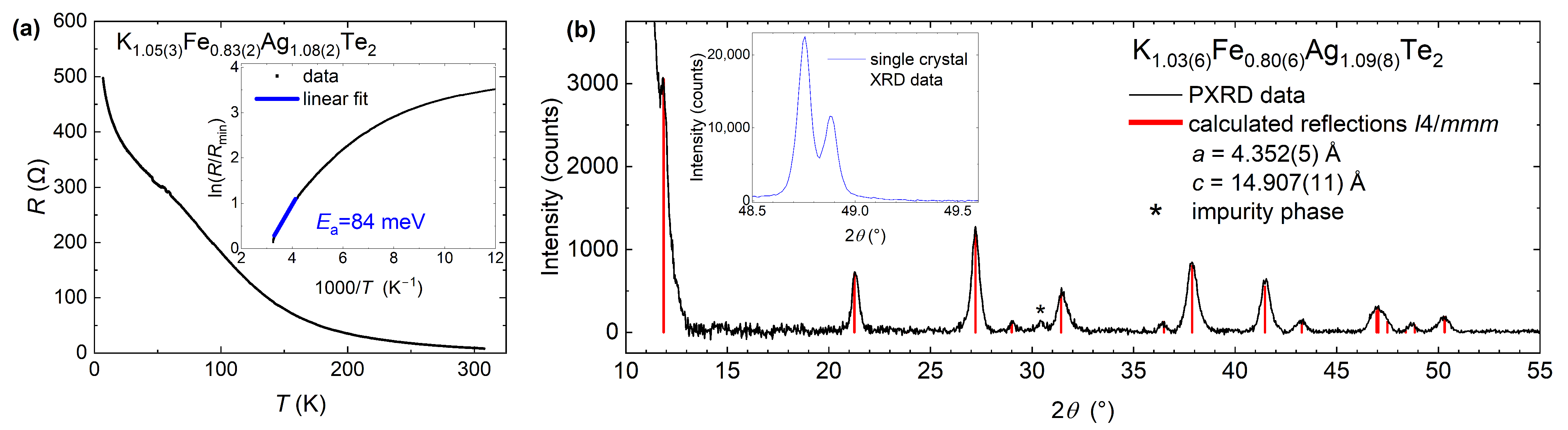
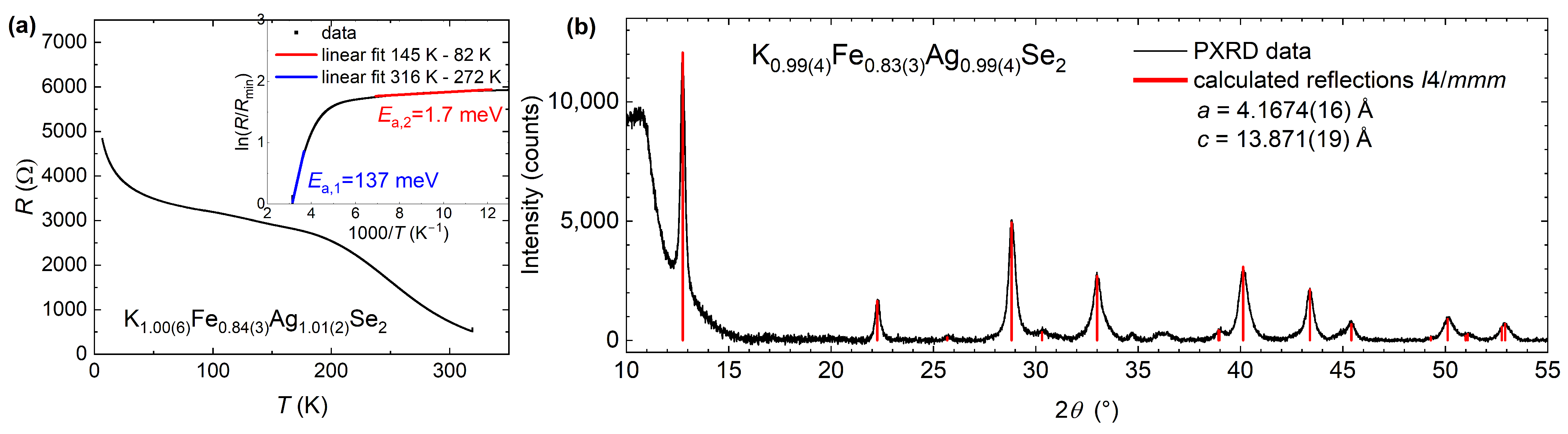
3.2. Characterization of Air-Sensitivity

Another property of the crystals that can be observed in the electron microscope is their high instability in air. Signs of starting oxidation are visible on the crystal surface after only a few minutes of air exposure. The oxidation ultimately leads to a darker and porous oxide layer. The formation of oxides becomes evident in mainly two forms, either growing dots inside the surface or small granules on top of the surface.
The signatures of oxidation in SE and BSE pictures are shown in Figure 8. The crystal in the top row was cleaved immediately before it was mounted on the sample holder of the electron microscope. It shows a uniform surface. The brightness of the BSE picture is the same over the entire crystal indicating no change in atomic number Z ¯ . In the crystal in the bottom row several dark or white areas can be seen in the BSE or SE picture, respectively. In those areas the surface has oxidized as confirmed by EDS measurements. Additionally, some small granules of oxide are on top of the flat surface layer which are difficult to see in the picture.
During the XRD measurements the powders are exposed to humidity and oxygen in air. Therefore, these measurements can be used to reliably characterize the air sensitivity of the material. The decomposition is faster for the tellurium-containing samples than for the samples containing selenium. This can be seen by comparing Figure 9a and Figure 9b which show the powder XRD patterns of K 1.03 ( 6 ) Fe 0.80 ( 6 ) Ag 1.09 ( 8 ) Te 2 and K 0.99 ( 4 ) Fe 0.83 ( 3 ) Ag 0.99 ( 4 ) Se 2 immediately after grinding and after several hours in air. In both cases, the height of the peaks that belong to the target phases decrease to the point where some peaks are barely visible anymore. At the same time, additional peaks appear and grow in intensity. For the tellurium containing samples this is a broader range of peaks at a 2 θ slightly over 30 ° . For the selenium-containing batch one striking peak at 29 . 5 ° appears. This peak can be either identified with K 3 Fe 2 Se 4 , K 0.8 Fe 2 Se 1.96 or elemental selenium. The other peaks that increase in intensity can be assigned to the oxides Fe 3 O 4 , K 3 FeO 4 and Fe 0.856 O.
The signs of sample oxidation over time in air show the necessity of fast and careful handling of the crystals for any measurement but also prove the air-tightness of the container because no oxidation is present immediately after opening the container.

4. Conclusions

In summary, we developed a novel stainless steel container, which enables the sealing of materials with high vapor pressure and reactivity, such as alkali metals. The sealing can be performed manually inside a glovebox and hence without any exposure of the starting materials to air. The sealing procedure is fast, easy and more reliable than the sealing e.g., of tantalum tubes by welding. The material is significantly cheaper than tantalum or tungsten. The container design can be easily adjusted to the user’s needs. As an example, this container was used to grow KFe 1 x Ag 1 + y C h 2 single crystals with tellurium and selenium on the chalcogen site. A growth from self-flux was optimized and successfully implemented, in which the formation of secondary phases could be suppressed. Even this highly-air sensitive material could be grown successfully demonstrating the well functioning container for the flux growth of alkali-containing tellurides and selenides.

Supplementary Materials

The following supporting information can be downloaded at: https://www.mdpi.com/article/10.3390/cryst13091332/s1. EDS data, X-ray diffraction and transport data underlying the present study are available.

Author Contributions

J.P., A.K. and A.E.B. conceptualized the research. J.P., N.S.S., J.M., A.K. and A.E.B. design the containers. J.P. and N.S.S. grew the single crystals. J.P., N.S.S., T.R.T., A.K. and A.E.B. performed and analyzed the measurements. J.P. and A.E.B. drafted the manuscript and all authors participated in the writing and review of the final draft. All authors have read and agreed to the published version of the manuscript.

Funding

This work was supported by the Deutsche Forschungsgemeinschaft (DFG) under CRC/TRR 288 (Project A02).

Data Availability Statement

The data presented in this study are available in the supplementary material https://www.mdpi.com/article/10.3390/cryst13091332/s1.

Acknowledgments

The authors acknowledge the help of the mechanical workshop of the physics department of the Ruhr-Universität Bochum for the fabrication of the steel container.

Conflicts of Interest

The authors declare no conflict of interest.

References

  1. Canfield, P.C.; Fisher, I.R. High-temperature solution growth of intermetallic single crystals and quasicrystals. J. Cryst. Growth 2001, 225, 155–161. [Google Scholar] [CrossRef]
  2. Canfield, P. Solution growth of intermetallic single crystals: A beginner’s guide. In Properties and Applications of Complex Intermetallics; World Scientific: Hackensack, NJ, USA, 2009; pp. 93–111. [Google Scholar]
  3. Jesche, A.; Canfield, P. Single crystal growth from light, volatile and reactive materials using lithium and calcium flux. Philos. Mag. 2014, 94, 2372–2402. [Google Scholar] [CrossRef]
  4. Tachibana, M. Beginner’s Guide to Flux Crystal Growth; Springer: Tokyo, Japan, 2017; pp. 82, 87. [Google Scholar]
  5. Kihou, K.; Saito, T.; Ishida, S.; Nakajima, M.; Tomioka, Y.; Fukazawa, H.; Kohori, Y.; Ito, T.; Uchida, S.I.; Iyo, A.; et al. Single Crystal Growth and Characterization of the Iron-Based Superconductor KFe2As2 Synthesized by KAs Flux Method. J. Phys. Soc. Jpn. 2010, 79, 124713. [Google Scholar] [CrossRef]
  6. EN 1.4841. Available online: https://ucpcdn.thyssenkrupp.com/_legacy/UCPthyssenkruppBAMXUK/assets.files/material-data-sheets/stainless-steel/stainless-steel-1.4841.pdf (accessed on 18 August 2023).
  7. Canfield, P.; Kong, T.; Kaluarachchi, U.; Jo, N. Use of frit-disc crucibles for routine and exploratory solution growth of single crystalline samples. Philos. Mag. 2016, 96, 84–92. [Google Scholar] [CrossRef]
  8. Lei, H.; Bozin, E.S.; Wang, K.; Petrovic, C. Antiferromagnetism in semiconducting KFe0.85Ag1.15Te2 single crystals. Phys. Rev. B 2011, 84, 060506. [Google Scholar] [CrossRef]
  9. Song, Y.; Cao, H.; Chakoumakos, B.C.; Zhao, Y.; Wang, A.; Lei, H.; Petrovic, C.; Birgeneau, R.J. Intertwined Magnetic and Nematic Orders in Semiconducting KFe0.8Ag1.2Te2. Phys. Rev. Lett. 2019, 122, 087201. [Google Scholar] [CrossRef] [PubMed]
  10. Ryu, H.; Lei, H.; Klobes, B.; Warren, J.B.; Hermann, R.P.; Petrovic, C. Spin glass in semiconducting KFe1.05Ag0.88Te2 single crystals. Phys. Rev. B 2015, 91, 174517. [Google Scholar] [CrossRef]
  11. Wang, B.; Guo, Z.; Sun, F.; Deng, J.; Lin, J.; Wu, D.; Yuan, W. The transition between antiferromagnetic order and spin-glass state in layered chalcogenides KFeAgCh2 (Ch = Se, S). J. Solid State Chem. 2019, 272, 126–130. [Google Scholar] [CrossRef]
Figure 1. (a) A container with separate iron sealing ring is disassembled into the main part, the iron sealing ring and the cap with the thread. At top and bottom are square ends which fit into a 14 mm open-end wrench. Three notches are lathed into the main part to simplify the opening of the container. (b) The container version with integrated sealing ring is shown. The 20 ° incline of the edge facing towards the reader is visible. (c) Inside the steel container a steel spring, a start crucible, a sieve and a catch crucible (shown from bottom left to top right) are placed in this order. Crucibles and sieve are made from alumina.
Crystals 13 01332 g001
Figure 2. Schematic overview including measurements of the container versions with (a) integrated sealing ring which has a 20 ° incline, and (b) separate iron sealing ring which has a 17 ° incline. The thickness of the iron sealing ring is 1.5 m m . This iron sealing ring is highlighted in the figure by a black border surrounding it.
Crystals 13 01332 g002
Figure 3. (a) Test heating of a steel container with a defective seal, enclosed in a fused silica ampoule. The visible attack on the fused silica from the inside shows that some potassium vapor escaped. Even though the quartz looks as if it would have cracks, the outside was still completely smooth and intact. (b) Successfully sealed steel container inside a fused silica tube after heating. No attacks on the fused silica are visible demonstrating the perfect seal. (c) Steelcontainer after heating in air to 1030 ° C during a test of the temperature profile described in the text. The filed area shows that only a thin surface layer of the container material is oxidized and also the iron sealing ring is not oxidized throughout (green arrow).
Crystals 13 01332 g003
Figure 4. (a) In the upper part is a cut open steel container shown after usage in a furnace. The dark color is attained during heating and is due to oxidation in a thin surface layer. In the lower part are (from left to right) the alumina catch crucible with a piece of solidified flux inside, the alumina start crucible and the steel spring. The sieve remained in the middle part of the steel container. The darker rings on the alumina crucibles stem from sawing the container open. (b) Freestanding single crystals of KFeAgTe 2 grown using a steel container.
Crystals 13 01332 g004
Figure 5. (a) Resistance of a single crystal with individual composition K 1.05 ( 3 ) Fe 0.83 ( 2 ) Ag 1.08 ( 2 ) Te 2 . Around 70 K the contacts were slightly unstable. (b) Powder XRD pattern from 10 ° to 55 ° with the expected reflections of the I 4 / m m m space group for the determined lattice parameters a = 4.352 ( 5 ) Å and c = 14.907 ( 11 ) Å in red. The asterisk marks a minor peak not explained by the I 4 / m m m space group. It can be associated with K 5 Te 3 which is part of the flux. At low 2 θ angles there is a large background probably caused by grease holding the powder. The insert shows part of a single crystal X-ray diffraction pattern with visible K α 1 /K α 2 -splitting and a peak of width of less than 0.09 ° . The broader, Lorentzian-shaped peak in the powder XRD pattern on the main panel result from damage of the malleable material during grinding.
Crystals 13 01332 g005
Figure 6. (a) Resistance of a single crystal with individual composition K 1.00 ( 6 ) Fe 0.84 ( 3 ) Ag 1.01 ( 2 ) Se 2 . (b) Powder XRD pattern from 10 ° to 55 ° with the expected reflections of the I 4 / m m m space group for the determined lattice parameters a = 4.1674 ( 16 ) Å and c = 13.871 ( 19 ) Å in red.
Crystals 13 01332 g006
Figure 7. Intergrown phases of KAg 3 Te 2 and KFe 0.8 Ag 1.1 Te 2 in a BSE picture. The KAg 3 Te 2 phase appears brighter than the K 0.99 ( 2 ) Fe 0.80 ( 8 ) Ag 1.22 ( 5 ) Te 2 because of the higher Z ¯ number of KAg 3 Te 2 .
Crystals 13 01332 g007
Figure 8. Crystal with surface cleaved immediately before the measurement in pictures from (a) secondary electrons and (b) in backscattered electrons. Crystal featuring different signs of oxidation on the surface in pictures from (c) secondary electrons and (d) in backscattered electrons. Visible are small granules of oxide on top of the surface (white in secondary electrons), larger oxidation dots (dark gray in backscattered electrons) and a growing oxide layer on the right.
Crystals 13 01332 g008
Figure 9. (a) Powder XRD pattern of tellurium-containing crystals started immediately after grinding the compound in air, compared to a pattern started 12.5 h later. The prevailing peaks have significantly reduced in intensity, some are barely visibly anymore. A series of new, broad peaks occurs at around 32°. One scan from 5° to 55° took 2.75 h. (b) Powder XRD pattern of selenium-containing crystals started immediately after grinding the compound in air, compared to a pattern started 25 h later. One scan from 5° to 55° took 2.75 h.
Crystals 13 01332 g009
Disclaimer/Publisher’s Note: The statements, opinions and data contained in all publications are solely those of the individual author(s) and contributor(s) and not of MDPI and/or the editor(s). MDPI and/or the editor(s) disclaim responsibility for any injury to people or property resulting from any ideas, methods, instructions or products referred to in the content.

