Article

The Influence of Deposition Temperature on the Microscopic Process of Diamond-like Carbon (DLC) Film Deposition on a 2024 Aluminum Alloy Surface

1
School of Materials Science and Engineering, Yingkou Institute of Technology, No. 46 Bowen Road, Yingkou 115014, China
2
Research Center for Corrosion and Erosion Process Control of Equipment and Material in Marine Harsh Environment, Guangzhou Maritime University, Guangzhou 510725, China
*
Author to whom correspondence should be addressed.
Crystals 2024, 14(11), 950; https://doi.org/10.3390/cryst14110950
Submission received: 12 September 2024 / Revised: 17 October 2024 / Accepted: 21 October 2024 / Published: 31 October 2024
(This article belongs to the Section Crystalline Metals and Alloys)

Abstract

:
In this experiment, plasma-enhanced chemical vapor deposition technology was used to deposit diamond-like carbon thin films on the surface of a 2024 aluminum alloy. The effects of deposition temperature on the microstructure, carbon, silicon, and aluminum element distribution, and film substrate adhesion of diamond-like carbon thin films were studied using field emission scanning electron microscopy, energy-dispersive spectroscopy, XRD, scratch gauge, and ultra-depth-of-field microscopy. The results showed that with the increase in deposition temperature, the thickness of DLC film decreased from 8.72 μm to 5.37 μm, and the film bonded well with the substrate. There is a clear transition layer containing silicon elements between the DLC film and the aluminum alloy substrate. The transition layer is a solid solution formed by aluminum and silicon elements, which increases the bonding strength between the film and substrate. C-Si and C-C exist in the form of covalent bonds and undergo orbital hybridization, making the DLC film more stable. When the deposition temperature exceeds the aging temperature of a 2024 aluminum alloy, it will affect the properties of the aluminum alloy substrate. Therefore, the deposition temperature should be below the aging temperature of the 2024 aluminum alloy for coating. At a deposition temperature of 100 °C, the maximum membrane substrate bonding force is 14.45 N. When a continuous sound signal appears and the friction coefficient is the same as that of the substrate, the film is completely damaged. From the super-depth map of the scratch morphology, it can be seen that, at a deposition temperature of 100 °C, a small amount of thin film detachment appears around the scratch.

1. Introduction

Owing to their low density, high specific strength, exceptional ductility, corrosion resistance, ease of processing, and formability, aluminum alloys have garnered widespread use, positioning themselves as the second most prevalent metal material following steel [1,2,3]. Aluminum alloys are extensively used as structural materials in aerospace, automobile, marine, and military fields, including skin panels, rivets, and rocket tanks [4,5,6]. Nonetheless, as industrial technology advances, aluminum alloys encounter challenges in meeting demanding application requirements due to their intrinsically low hardness and limited wear resistance [7,8].
Surface modification technology can effectively improve the surface hardness and wear resistance of aluminum alloys. In recent years, surface modification technology has made rapid progress. Among them, surface modification technologies such as plasma-enhanced chemical vapor deposition (PECVD) [9], microwave plasma jet chemical vapor deposition (MPJCVD) [10], chemical vapor deposition (CVD) [11], ion beam-assisted deposition (IBAD) [12], and microwave plasma chemical vapor deposition (MPCVD) [13] have been greatly developed. The development of surface-modification technology has also promoted the application of various surface-modified materials. DLC film materials have attracted widespread attention due to their high hardness, low friction coefficient, and high chemical stability. The use of PECVD technology to prepare DLC films has wide applications in improving the hardness and wear resistance of lightweight alloys and bearing alloys [14,15]. Normally, temperature has a significant impact on the performance of DLC films [16,17,18,19]. Research has shown [16,17,20,21,22] that deposition temperature is one of the important factors affecting the hybridization mode of sp2 and sp3 bonds. The content of sp2 and sp3 bonds plays a decisive role in the mechanical and tribological properties of DLC films. Ding Xuli et al. [16] studied the effect of deposition temperature on the physical properties such as optical transmittance and resistivity of DLC films but did not conduct further in-depth research on their mechanical and electrical properties. Huang et al. [18] deposited DLC films on the surface of YG6 cemented carbide using a linear ion source at different temperatures. Their study found that temperature has a significant impact on the surface roughness of DLC films and explained the corresponding mechanism of influence. Bhargava et al. [19] focused on studying the growth process of DLC films at different temperatures, but due to the high temperatures used in their research, their results cannot provide a direct reference for the growth mechanism of DLC films deposited on aluminum alloy surfaces.
In summary, current research on the influence of deposition temperature on the properties of DLC films mainly focuses on physical properties, such as optical characteristics, electrical resistivity, and tribological characteristics. However, there is relatively little research on the effect of temperature on the sp2 and sp3 bond content in DLC films and the resulting changes in mechanical and tribological properties. Therefore, it is of great significance to study the influence of deposition temperature on the properties of DLC films and 2024 aluminum alloys.

2. Experimental Process

2.1. Experimental Materials

The experimental material is a 2024 aluminum alloy. The sample was cut and processed from a 2024 aluminum alloy rod into a cylindrical shape with dimensions of Ø 20 mm × 10 mm. Afterwards, metallographic sandpaper was used to polish the samples sequentially to 2000 #, and metallographic grinding paste was used to polish them again. The polished sample was placed in an alcohol solution for ultrasonic cleaning. After cleaning, the sample was taken out and dried, then placed in a drying oven for later use. The chemical composition of 2024 aluminum alloy as the experimental substrate material is shown in Table 1.

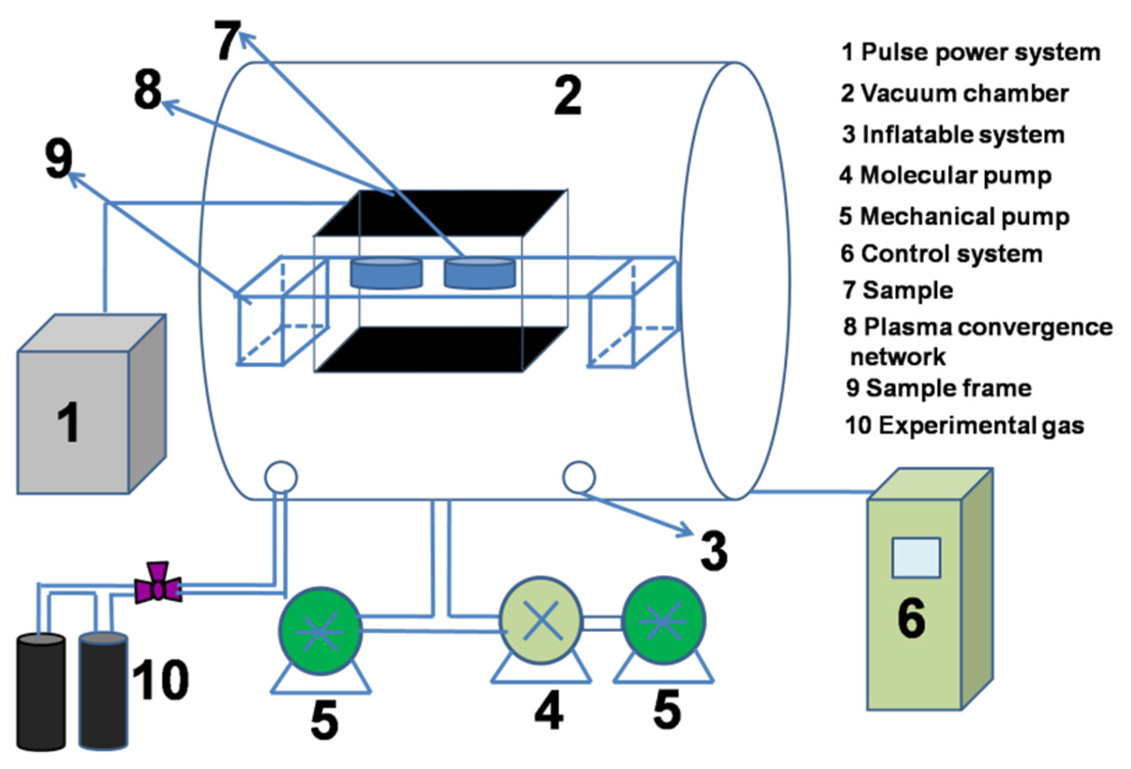
2.2. Experimental Process and Parameters

Place the preprocessed aluminum alloy sample in the chamber of the PECVD equipment (CVD Equipment Corporation, NY 11722, USA), turn on the mechanical pump and molecular pump, evacuate the furnace to 3 × 10⁻³ Pa, and heat the sample to the required deposition temperature for the experiment. Then, introduce 100 sccm of argon gas into the furnace for 20 min to remove any unextracted air. Connect the pulse power supply system to increase the voltage from −800 V to −3300 V at a rate of −100 V every 10 min, and clean the surface of the 2024 aluminum alloy with a pulse bias voltage of −3300 V for 60 min. This can not only remove the dense oxide film on the surface of the 2024 aluminum alloy but also avoid obvious etching phenomena on the surface of the 2024 aluminum alloy caused by transient high plasma density. After cleaning, keep the pulse bias constant, turn off the argon gas, and introduce 40 sccm of tetramethylsilane gas into the furnace for 40 min. Turn off the tetramethylsilane gas and introduce a ratio of 1:3 of argon and acetylene gas into the furnace. Keep all experimental parameters unchanged and deposit the sample for 5 h. The experimental process parameters are shown in Table 2.
Figure 1 is a schematic diagram of the plasma-enhanced chemical vapor deposition equipment used in this experiment. This experimental equipment mainly consists of a pulse power supply system, a vacuum chamber, an exhaust system, an inflation system, and a control system.
The cross-sectional morphology of DLC films was observed using a ∑ IGMA/HD scanning electron microscope (SEM) produced by Carl Zeiss in Oberkochen, Germany, and the distribution of C, Si, and Al elements at different depths of the DLC films was analyzed using EDS. D/Max 2400 XRD (Rigaku, Tokyo, Japan) was used to analyze the phase composition of the transition layer, with a scanning angle of 20–90°. An MST-4000 scratch tester (CSM Instruments SA, Peseux, Switzerland) was used to detect the adhesion between the film and substrate. The final load was 100 N, the loading speed was 100 N/min, and the scratch length was 5 mm. The morphology of scratches after the scratch experiments was observed using a VHX-500F ultra-depth microscope (KEYENCE Corporation, Osakam, Japan), and the brittleness and toughness of the film were analyzed by comparing the failure length and the degree of film detachment.

3. Experimental Results

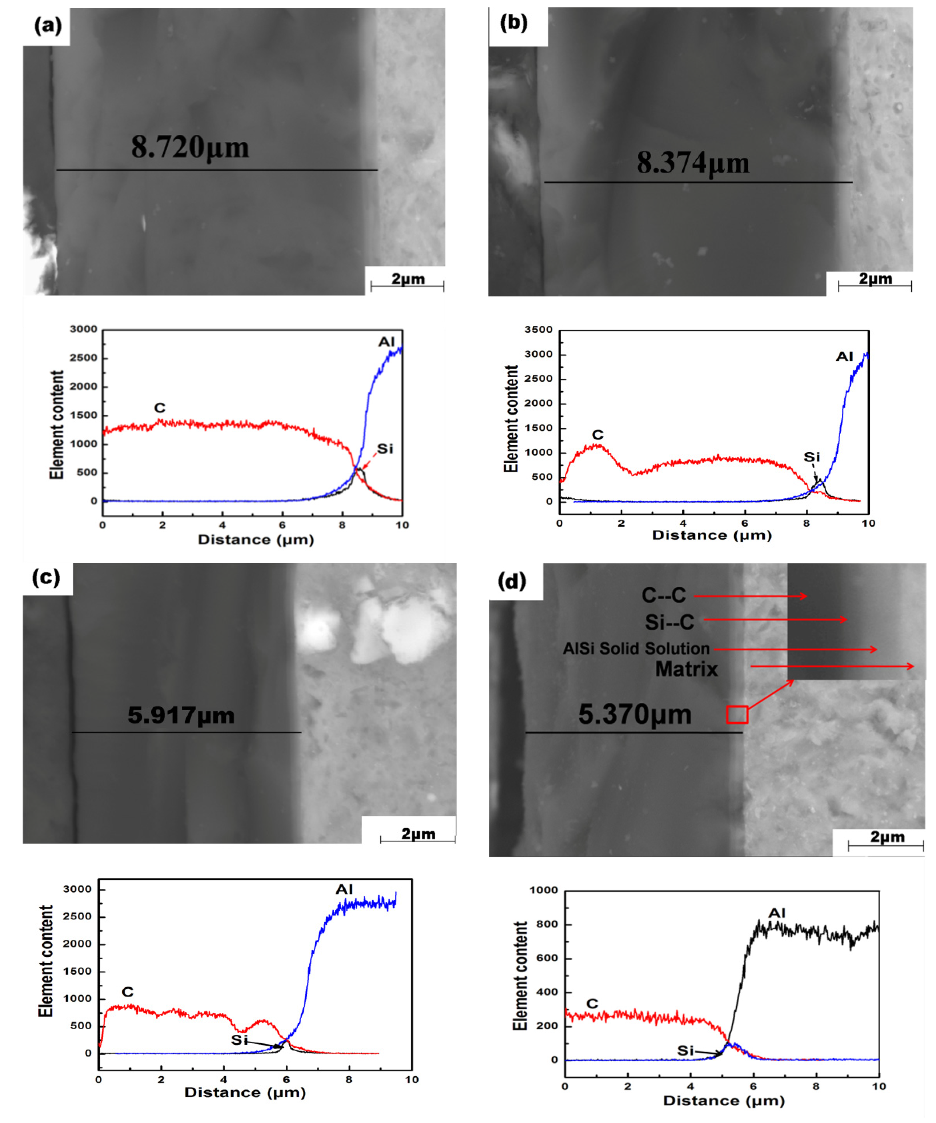
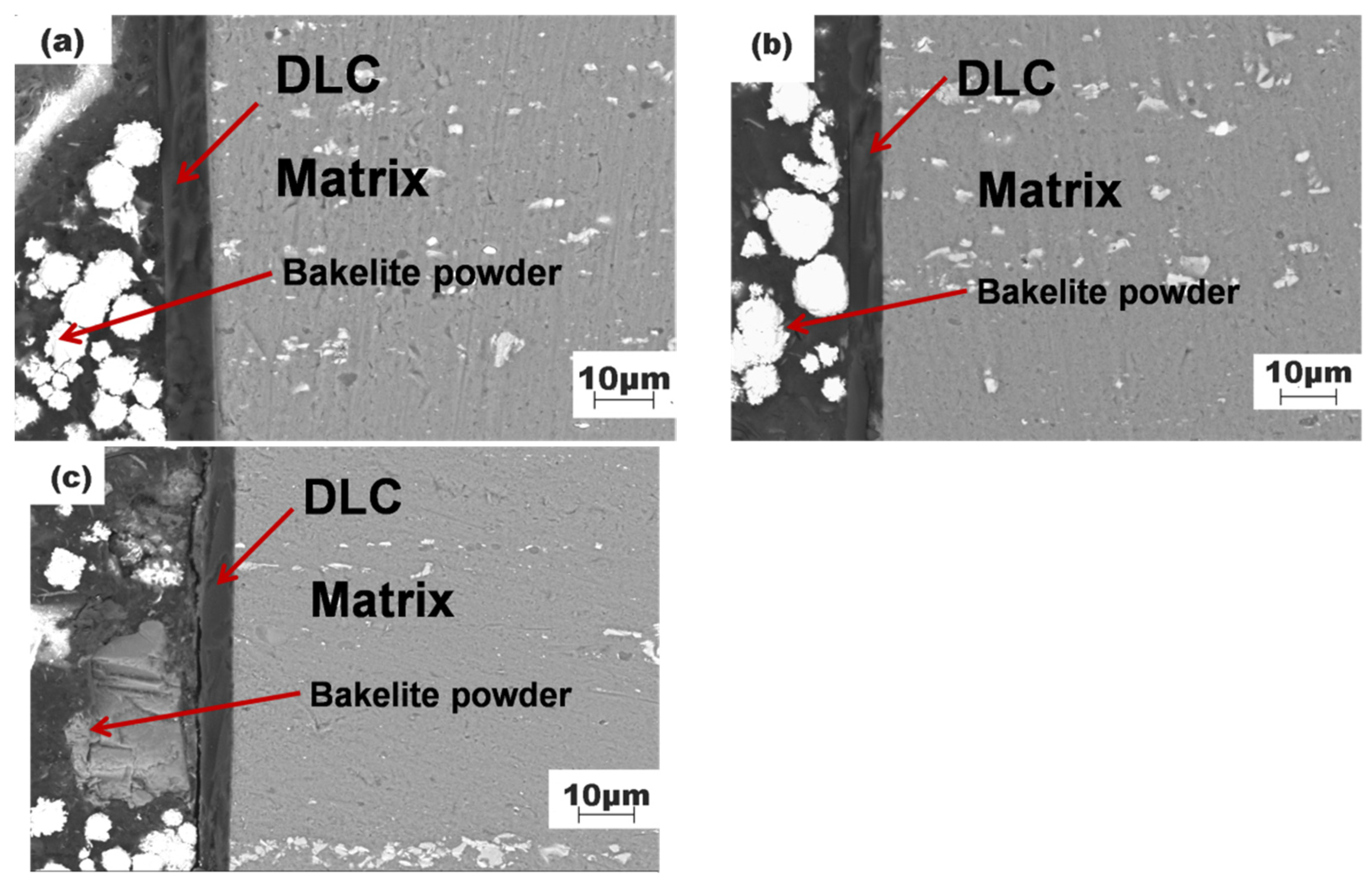
3.1. Sectional Morphology of DLC Films and Substrates at Different Temperatures

Figure 2 shows the cross-sectional morphology, the distribution of C, Si, and Al elements, and the film thickness of DLC films at different deposition temperatures.
From the figure, it can be seen that there is a clear transition layer between the film and the substrate and that the film transition layer substrate bond is good. According to the EDS analysis, the main element of the outermost DLC film is C, while the main elements of the transition layer are C, Si, and Al. The main element of the innermost substrate is Al. From the XRD results in Figure 3, it can be seen that the Al9Si phase appears at 38°, 44°, and 82°, with preferred orientations of (111), (200), and (222), respectively. At the same time, the Si5C3 phase appears at 44°, with a preferred orientation of (210). From the partially enlarged image in Figure 2d, it can be seen that a layer of aluminum–silicon solid solution is first deposited on the surface of 2024 aluminum alloy, followed by a layer of C-Si layer on top of the aluminum–silicon solid solution, and finally, a layer of C-C layer is deposited. The thickness of the DLC film decreases from 8.720 μm to 5.370 μm with the increase in deposition temperature.
Figure 4 shows the distribution of the second phase in the substrate at different deposition temperatures. When the deposition temperature is below 125 °C, the second phase in the matrix is in a dispersed distribution state, while when the deposition temperature is 150 °C, the second phase in the matrix undergoes segregation.

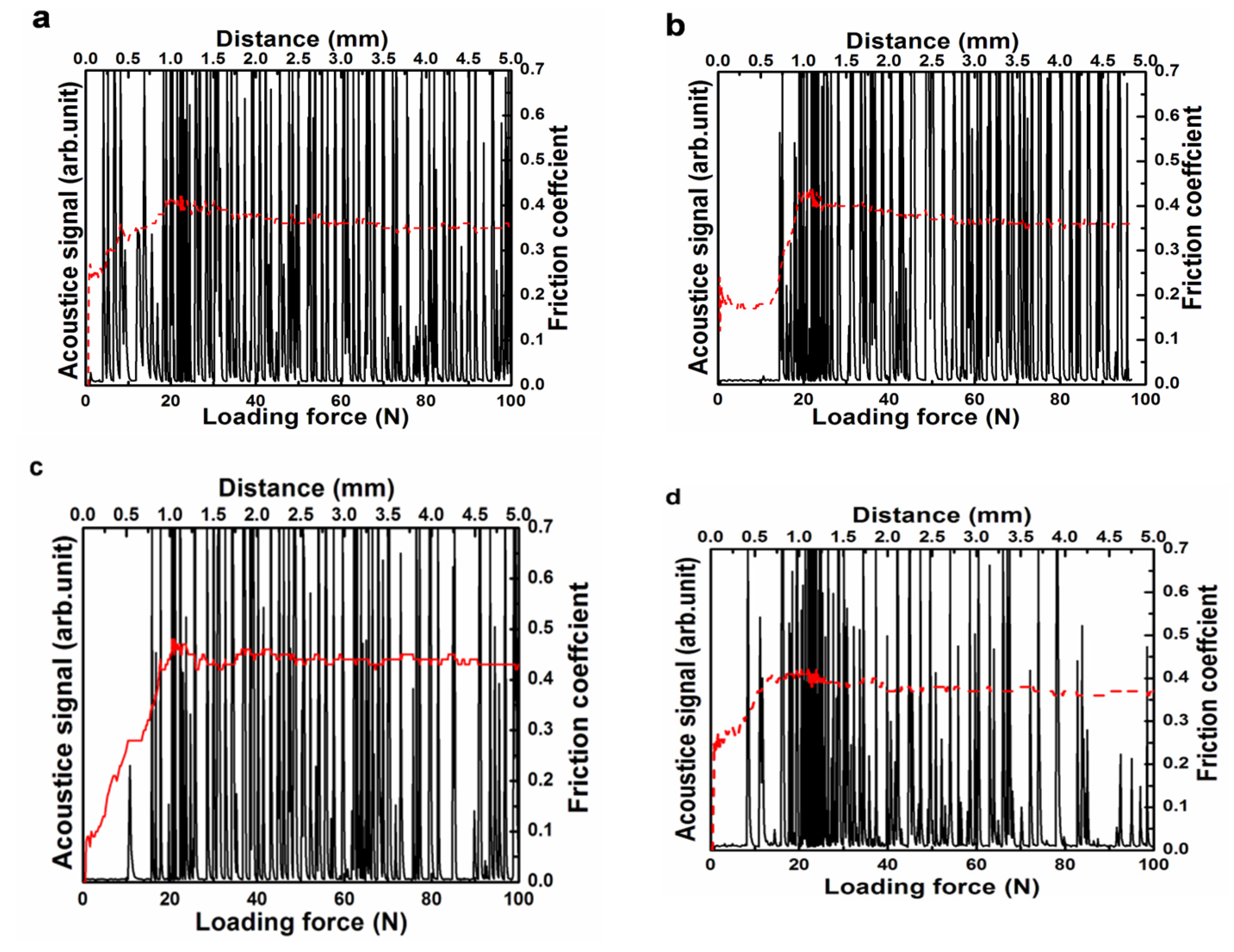
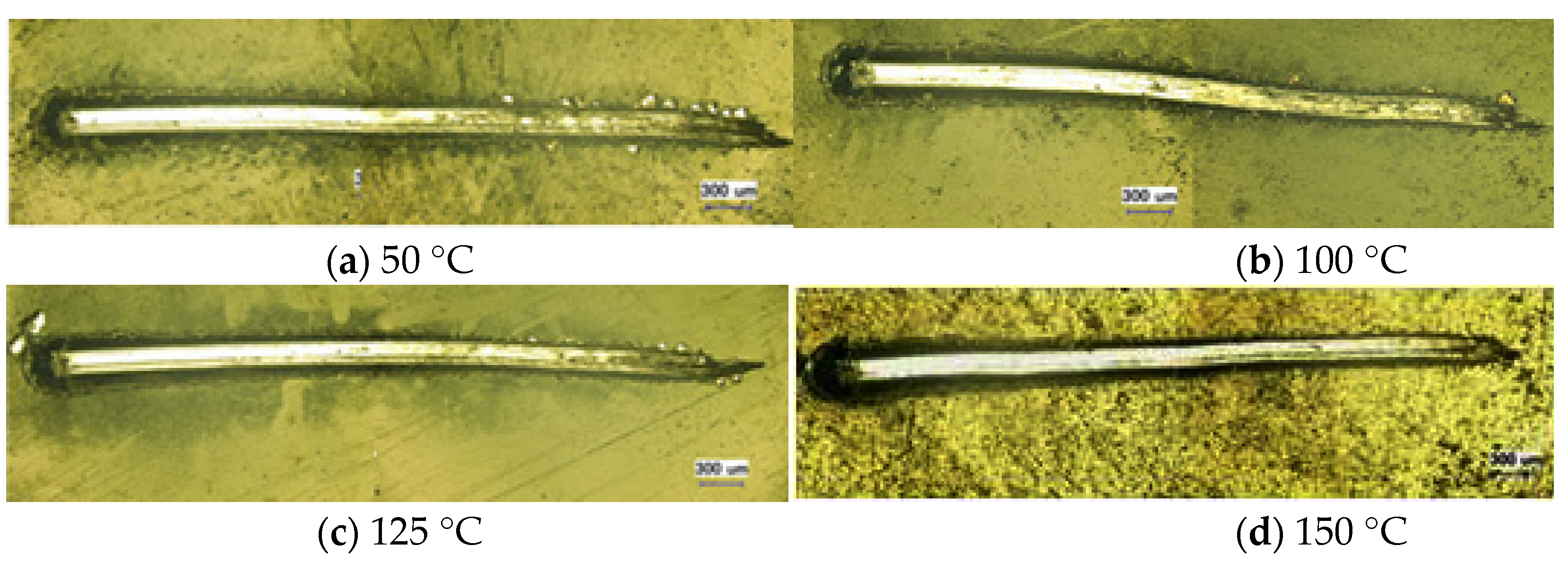
3.2. Membrane Substrate Adhesion at Different Temperatures

Figure 5 shows the variation curves of the acoustic signal and friction coefficient with loading force during scratching of the DLC film and aluminum alloy substrate at different deposition temperatures. It is generally believed that the loading force corresponding to the first location where the sound signal appears is the membrane substrate bonding force. When the friction coefficient tends to stabilize, the location where the sound signal appears continuously is generally considered to be in a completely failed state of the thin film. When the deposition temperatures are 50 °C, 100 °C, 125 °C, and 150 °C, the membrane substrate bonding forces are 4.86 N, 14.43 N, 10 N, and 9.8 N, respectively. It can be seen that the membrane substrate bonding force is the highest when the deposition temperature is 100 °C.
Figure 6 shows the super-depth map of DLC film scratches at different deposition temperatures. When the deposition temperature is 50 °C, there is a significant cracking phenomenon around the scratches. However, when the deposition temperature rises to 100 °C, the cracking phenomenon of the film significantly decreases, and the cracked area does not leak out of the substrate. When the sedimentation temperature is 125 °C, there is a small amount of detachment around the scratch. When the sedimentation temperature is 150 °C, there is also a slight detachment phenomenon around the scratch.

4. Discussion

4.1. Discussion of the Relationship Between Deposition Temperature and Film Thickness

From Figure 2, it can be seen that as the deposition temperature increases, the thickness of the DLC film gradually decreases. During the deposition process, the thickness of the DLC film is determined by the number of particles in the experimental chamber and the energy carried by the particles. Firstly, the relationship between sedimentation temperature and particle number is studied, and its calculation formula is as follows [23]:
p   =   2 3 n E k
E k   =   3 2 k T
Among them, P is the cavity pressure, k is the Boltzmann constant (1.38 × 10⁻²³ J/k), n is the number of gas particles per unit volume, T is the thermodynamic temperature of the system (k), and Ek is the kinetic energy carried by the particles. Substituting Formula (2) into Formula (1) yields the following:
n   =   P k T
From Formula (3), it can be seen that the number of particles in the system is determined by the pressure and temperature of the system. According to the experimental parameters, under the same pressure, the number of particles in the system is only determined by the deposition temperature. Assuming that the number of particles in the system under the experimental conditions of sample #4 is taken as the measurement unit, according to Formula (3), the number of particles in the system during the deposition process of sample #3 is 1.063n, the number of particles in the system during the deposition process of sample #2 is 1.134n, and the number of particles in the system during the deposition process of sample #1 is 1.311n. It indicates that as the sedimentation temperature increases, the number of particles per unit volume decreases.
The energy carried by each particle is related to the total energy of the system and the collision loss energy between particles. In this experiment, the total energy provided by the system is constant, while the collision loss energy between particles is related to the average free path size of the particles. Firstly, Ar is represented by A, C2H2 is represented by C, and the average free path of particles is determined by the gas particles’ velocity and the collision frequency between particles. The formula for calculating the average free path of particles is as follows [24,25]:
λ   =   v / z
Among them, λ is the average free path of particles, ν is the velocity of gas particles, and z is the collision frequency between particles.
The velocity of a particle is determined by the sum of the velocities of particle A and particle C. Therefore, the velocity of the particles obtained from Formula (2) is calculated as follows:
v A   =   3 k T m A v C   =   3 k T m C
v 2   =   v A 2   +   v C 2   =   3 k T m A   +   3 k T m C   =   3 k T m A m C ( m A   +   m C )
The average collision frequency of particles is composed of the collision frequency of A and C plus the collision frequency of C and C. The average collision frequency of particles is calculated as follows:
Z A C   =   π 4 ( d A   +   d C ) 2 v A C n A Z C C   =   2 π d C 2 v C n C
Z   =   Z C C   +   Z A C   =   π 4 ( d A   +   d C ) 2 v A C n A   +   2 π d C 2 v C n C
Substituting Formulas (6) and (8) into Formula (4) yields the following:
λ   =   1 π [ 1 4 ( d A   +   d C ) 2 m A   +   m C m C n A   +   2 d C 2 n C ] 1
Among them, dA and dC are the particle diameters of A and C, mA and mC are the particle masses of A and C, and nA and nC are the particle numbers of argon and acetylene, respectively.
According to Formula (9), the average free path of a particle is inversely proportional to the number of particles in the system. The more particles there are, the shorter the average free path and the more collisions there are, resulting in more energy loss for the particles and lower residual energy. As the deposition temperature increases, the number of particles in the vacuum chamber gradually decreases, but the total energy provided by the pulse power supply is constant, and the smaller the number of particles, the greater the energy obtained per unit particle. However, during the process of particles moving to the surface of the 2024 aluminum alloy, collisions are bound to occur, and the energy loss of particle collisions is inversely proportional to the average particle free path. When the sedimentation temperature increases, the average free path of its particles increases, resulting in a decrease in collision frequency and a reduction in particle energy loss. In summary, as the deposition temperature increases, the number of particles in the vacuum chamber gradually decreases, and the energy obtained per unit particle increases. However, the energy loss per unit particle decreases, resulting in an increase in the remaining energy per unit particle. In other words, an increase in deposition temperature leads to a decrease in the number of particles in the vacuum chamber and an increase in the residual energy of the particles. The higher the residual energy of the particles, the less likely they are to deposit on the surface of the 2024 aluminum alloy. Therefore, an increase in deposition temperature leads to a gradual thinning of the DLC film’s thickness.
From Figure 4, it can be seen that when the deposition temperature reaches 150 °C, the copper–aluminum alloy phase in the 2024 aluminum alloy undergoes segregation. When the deposition temperature is below 125 °C, the copper–aluminum alloy phase in the aluminum alloy is dispersed and distributed in the matrix. This is because the aging temperature of the 2024 aluminum alloy is generally 130 °C [26]. When the deposition temperature exceeds 130 °C and the deposition process lasts for 5 h, it is equivalent to an over-aging treatment of the 2024 aluminum alloy, which causes the second phase originally dispersed in the 2024 aluminum alloy matrix to undergo segregation. In order to not change the properties of the 2024 aluminum alloy itself, the deposition of the DLC film should be carried out below the aging temperature of the 2024 aluminum alloy.

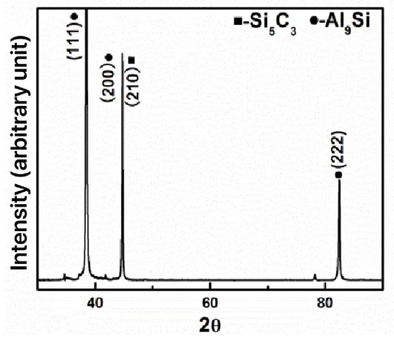
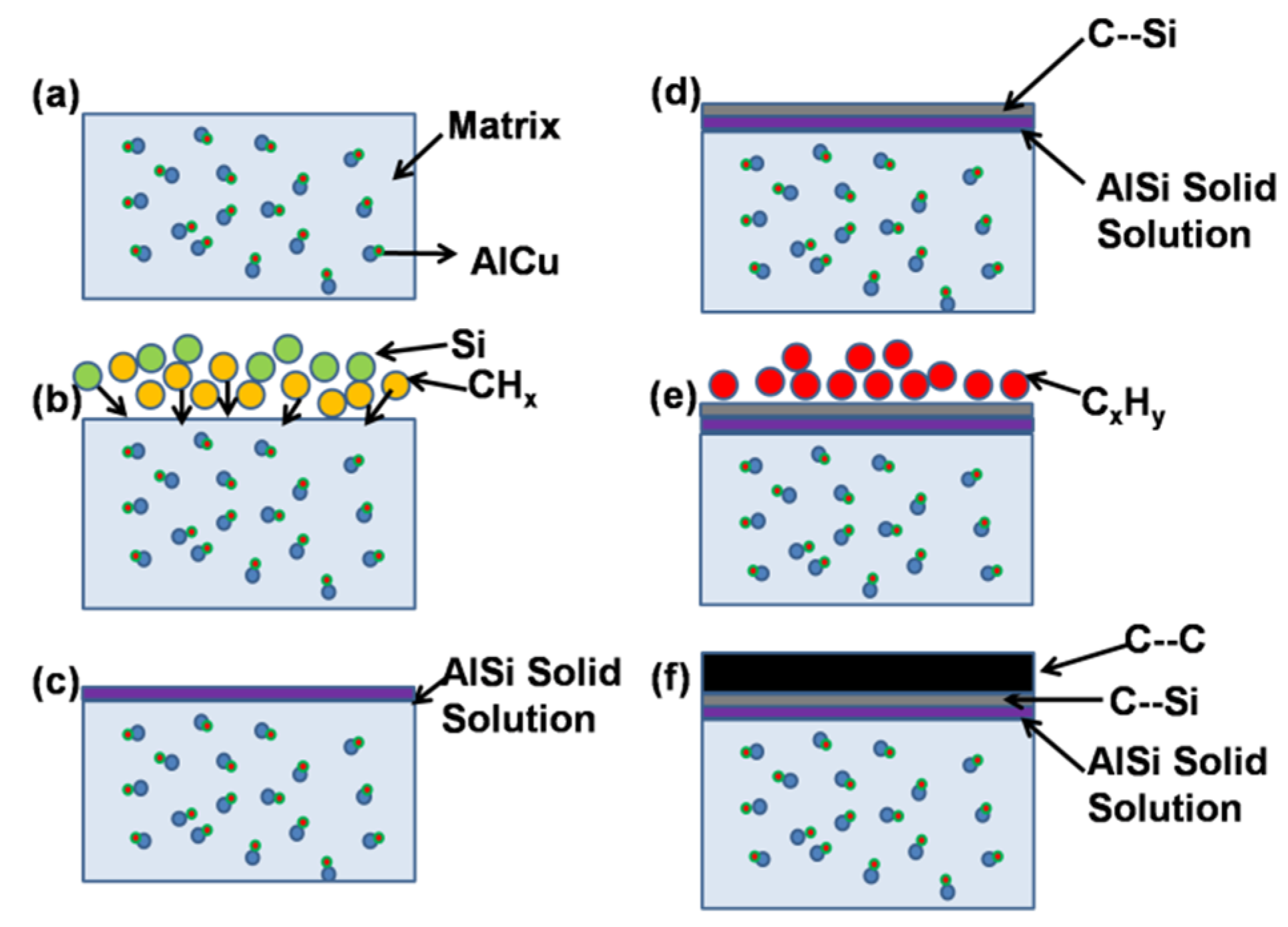
4.2. Discussion on Formation Mechanism of DLC Thin Films

Figure 7 is a schematic diagram of the DLC film deposition process. Figure 7a is a schematic diagram of the aluminum alloy matrix, with the AlCu phase dispersed in the matrix. When a certain amount of tetramethylsilane is introduced into the cavity, it decomposes under the action of pulse voltage, and the decomposed silicon particles and hydrocarbon particles move towards the surface of the 2024 aluminum alloy (Figure 7b). In the periodic table of chemical elements, silicon is adjacent to aluminum and they have electronegativities of 1.90 and 1.61, respectively [27]. Due to the close electronegativity of silicon and aluminum elements, Si particles and Al particles are prone to forming solid solutions. When silicon particles move to the surface of the 2024 aluminum alloy, they first form a solid solution with the aluminum particles, thereby improving the bonding strength between the substrate and the film (Figure 7c). As shown in Figure 3, Al9Si and Si5C3 formed on the surface of the 2024 aluminum alloy, indicating that, with the prolongation of time, Si became supersaturated in Al and could not form a solid solution, forming a C-Si transition layer. The atomic numbers of carbon atoms and silicon atoms are 6 and 14, respectively, and their outermost electron numbers are both four. In order to achieve a stable structure with the outermost eight electrons, during the deposition process, carbon particles and silicon particles form covalent bonds while undergoing orbital hybridization [28,29]. Under the action of a pulsed power supply, carbon particles form unpaired electrons with all four electrons on the 2s and 2p orbitals, forming four covalent bonds with the outermost four electrons of silicon particles. Under hybridization, the number of bonds formed increases, and the electron cloud becomes denser in the direction of the tetrahedral vertices, making the bonding ability stronger and the deposited film more stable (Figure 7d). After depositing a certain thickness of the transition layer, tetramethylsilane is turned off and a certain proportion of argon and acetylene gas is introduced into the chamber. Argon gas is used to increase the ionization rate of acetylene gas, causing it to decompose into hydrocarbon particles. The ionized carbon particles also move towards the surface of the transition layer (Figure 7e). A C-C layer is formed on top of the C-Si layer, and due to the same carbon silicon structure, the method of forming the C-C layer is basically the same as that of forming C-Si. After deposition, a stable DLC film (Figure 7f) was obtained on the surface of the 2024 aluminum alloy.

5. Conclusions

With the increase in deposition temperature, the thickness of DLC film decreased from 8.72 μm to 5.37 μm, and the film bonded well with the substrate. There is a clear transition layer containing Si elements between the DLC film and the aluminum alloy substrate. The transition layer is a solid solution formed by Al and silicon elements, which increases the bonding strength between the film and substrate. C-Si and C-C exist in a covalent bond form and undergo orbital hybridization, making the DLC film more stable. When the deposition temperature exceeds the aging temperature of the 2024 aluminum alloy, it will affect the properties of the aluminum alloy substrate. Therefore, the deposition temperature should be below the aging temperature of the 2024 aluminum alloy for coating.
At a deposition temperature of 100 °C, the maximum membrane substrate bonding force is 14.45 N. When a continuous sound signal appears and the friction coefficient is the same as that of the substrate, the film is completely damaged. From the super-depth map of the scratch morphology, it can be seen that at a deposition temperature of 100 °C, a small amount of thin film detachment appears around the scratch.

Author Contributions

Methodology, L.Y.; formal analysis, B.S.; investigation, T.Z.; resources, L.G.; data curation, W.H.; writing—original draft preparation, T.L.; writing—review and editing. All authors have read and agreed to the published version of the manuscript.

Funding

This research was funded by the Basic Research Project of the Liaoning Provincial Department of Education, number LJKQZ20222288, the Liaoning Provincial Engineering Research Center for High-Value Utilization of Magnesite, number LMNK2024020209, and the 2023 Joint Fund Project Doctoral Research Launch Project, project number 2023012097-JH3/4500.

Data Availability Statement

Data is contained within the article.

Acknowledgments

This work has been supported by the Basic Research Project of the Liaoning Provincial Department of Education (LJKQZ20222288), the Liaoning Provincial Engineering Research Center for High-Value Utilization of Magnesite (LMNK2024020209), and the 2023 Joint Fund Project Doctoral Research Launch Project, project number 2023012097-JH3/4500.

Conflicts of Interest

The authors declare no conflict of interest.

References

  1. David, M.T.; Wilson, P.; Mahesh, R.; Ramesh, C.; Sagayaraj, P. Chemo-resistive detection of hydrogen in argon using Pd nanoparticles on TiO2 nanotubes prepared via rapid breakdown anodization. Mater. Res. Express 2019, 7, 114221. [Google Scholar] [CrossRef]
  2. Zhang, Y.G.; Chen, Y.L.; Zhang, Y.; Bian, G.X. The long-term corrosion performance and adhesion properties of 7B04 aluminum alloy/anodic film/epoxy primer system in acidic NaCl solution. Mater. Corros. 2021, 73, 93–105. [Google Scholar] [CrossRef]
  3. Ding, M.Y.; Yu, M.; Hua, J.W.; Chen, H. Effect of inclusion on performance of A6N01 aluminum alloy joints. Mater. Express 2020, 10, 1395–1403. [Google Scholar] [CrossRef]
  4. Zhang, Y.; Li, H.; Li, Z.X.; Mariusz, B.; Senkara, J. Quantitative analysis of the solute redistribution and precipitate of Al-Mg-Si series alloys resistance spot welds after post-weld heat treatment. J. Mater. Res. Technol. 2021, 15, 5906–5919. [Google Scholar] [CrossRef]
  5. Qian, S.H.; Zhang, T.M.; Chen, Y.H.; Xie, J.L.; Chen, Y.; Lin, T.S.; Li, H.X. Effect of ultrasonic impact treatment on microstructure and corrosion behavior of friction stir welding joints of 2219 aluminum alloy. J. Mater. Res. Technol. 2022, 18, 1631–1642. [Google Scholar] [CrossRef]
  6. Zhou, S.Y.; Wu, K.; Yang, G.; Wu, B.; Qin, L.Y.; Wu, H.; Yang, C.Y. Microstructure and mechanical properties of wire arc additively manufactured 205A high strength aluminum alloy: The comparison of as-deposited and T6 heat-treated samples. Mater. Charact. 2022, 189, 111990. [Google Scholar] [CrossRef]
  7. Ji, L.; Wang, H.; Shi, M. Analysis of corrosion resistance of lightweight aluminum alloy sheet in the friction-stir joint area. Mater. Express 2020, 10, 1352–1357. [Google Scholar] [CrossRef]
  8. Zhang, P.; Zuo, Y. Effects of pore parameters on performance of anodic film on 2024 aluminum alloy. Mater. Chem. Phys. 2019, 231, 9–20. [Google Scholar] [CrossRef]
  9. Lin, S.-C.; Wang, C.-C.; Tien, C.-L.; Tung, F.-C.; Wang, H.-F.; Lai, S.-H. Fabrication of Aluminum Oxide Thin-Film Devices Based on Atomic Layer Deposition and Pulsed Discrete Feed Method. Micromachines 2023, 14, 279. [Google Scholar] [CrossRef]
  10. Hsu, H.-Y.; Yen, J.-S.; Lin, C.-Y.; Liu, C.-W.; Aranganadin, K.; Lin, C.-R.; Sun, J.-S.; Lin, M.-C. Extraordinary Field Emission of Diamond Film Developed on a Graphite Substrate by Microwave Plasma Jet Chemical Vapor Deposition. Appl. Sci. 2023, 13, 2531. [Google Scholar] [CrossRef]
  11. Milenov, T.; Trifonov, D.; Kalchevski, D.A.; Kolev, S.; Avramova, I.; Russev, S.; Genkov, K.; Avdeev, G.; Dimov, D.; Karaivanova, D.M.; et al. Study of the Chemical Vapor Deposition of Nano-Sized Carbon Phases on {001} Silicon. Materials 2023, 16, 7190. [Google Scholar] [CrossRef] [PubMed]
  12. Shang, P.; Ma, Y.; Zhang, Z.; Sun, P.; Liu, H.; Shi, H.; Lin, Q.; Xue, T.; Ji, Y. The Effects of Hemisphere Dome Orientation on the Structure of Diamond-like Carbon Film Prepared Using Ion Beam Assisted Deposition. Materials 2023, 16, 1773. [Google Scholar] [CrossRef] [PubMed]
  13. Hong, S.P.; Lee, K.-I.; You, H.J.; Jang, S.O.; Choi, Y.S. Scanning Deposition Method for Large-Area Diamond Film Synthesis Using Multiple Microwave Plasma Sources. Nanomaterials 2022, 12, 1959. [Google Scholar] [CrossRef] [PubMed]
  14. Robertson, J. Diamond-like amorphous carbon. Mater. Sci. Eng. Rev. 2002, 37, 129–181. [Google Scholar] [CrossRef]
  15. Roy, M.E.; Whiteside, L.A.; Xu, J.; Katerberg, B.J. Diamond-like carbon coatings enhance the hardness and resilience of bearing surfaces for use in joint arthroplasty. Acta Biomater. 2010, 6, 1619–1624. [Google Scholar] [CrossRef] [PubMed]
  16. Ding, X.; Li, Q.; Kong, X. Optical and electrical properties evolution of diamond-like carbon thin films with deposition temperature. Chin. Phys. Lett. 2009, 26, 027802. [Google Scholar]
  17. Roman, E.; Kalin, M.; Vizintin, J. The effect of temperature on the tribological mechanisms and reactivity of hydrogenated amorphous diamond-like carbon coatings under oil-lubricated conditions. Thin Solid Film. 2007, 515, 3644–3652. [Google Scholar]
  18. Huang, L.; Yuan, J.T.; Wang, Z.H.; Yu, B.B. Effect of the temperature on diamond-like carbon (DLC) thin film based on LIS. Appl. Mech. Mater. 2013, 421, 212–216. [Google Scholar] [CrossRef]
  19. Bhargava, S.; Bist, H.D.; Narlikar, A.V.; Samanta, S.B.; Narayan, J.; Tripathi, H.B. Effect of substrate temperature and heat treatment on the microstructure of diamondlike carbon films. J. Appl. Phys. 1996, 79, 1917–1925. [Google Scholar] [CrossRef]
  20. Mei, X.; Ma, T. Effects of substrate temperature on the chemical structure of diamond-like carbon films deposited by high-intensity pulsed ion beam ablation. Chem. J. Chin. Univ. 2003, 24, 1262–1265. [Google Scholar]
  21. Ji, X.; Hao, J.; Xu, Z. Effect of deposition temperature on surface morphology and perfor mance of diamond-like-carbon coatings. Mater. Mech. Eng. 2014, 38, 40–45. [Google Scholar]
  22. Mößner, C.; Grant, P.; Tran, H.; Clarke, G.; Lockwood, D.J.; Labbe, H.J.; Mason, B.; Sproule, I. Characterization of diamond-like carbon by raman spectroscopy, xps and optical constants. Thin Solid Film. 1998, 317, 397–401. [Google Scholar] [CrossRef]
  23. Dirk, D.; Taylor, C.E.; Ladner, E.P. Novel Techniques for the Conversion of Methane Hydrates. Stud. Surf. Sci. Catal. 2001, 136, 543–548. [Google Scholar]
  24. Dongari, N.; Zhang, Y.; Reese, J.M. Molecular free path distribution in rarefied gases. J. Phys. D Appl. Phys. 2011, 44, 125502. [Google Scholar] [CrossRef]
  25. Lutisan, J.; Cvengro, J. Mean free path of molecules on molecular distillation. Chem. Eng. J. Biochem. Eng. J. 1995, 56, 39–50. [Google Scholar] [CrossRef]
  26. Alexopoulos, N.D. On the corrosion-induced mechanical degradation for different artificial aging conditions of 2024 aluminum alloy. Mater. Sci. Eng. A 2009, 520, 40–48. [Google Scholar] [CrossRef]
  27. Zanatta, A.; Chambouleyron, I. Local electronegativity and chemical shift in Si and Ge based molecules and alloys. Solid State Commun. 1995, 95, 207–210. [Google Scholar] [CrossRef]
  28. Ohshita, J.; Tanaka, D.; Matsukawa, J.; Mizumo, T.; Yoshida, H.; Ooyama, Y.; Harima, Y. Hybridization of Carbon Nanotubes with Si–π Polymers and Attachment of Resulting Hybrids to TiO2 Surface. Chem. Lett. 2011, 40, 87–89. [Google Scholar] [CrossRef]
  29. De Nicola, F.; Hines, P.; De Crescenzi, M.; Motta, N. Moth-eye effect in hierarchical carbon nanotube anti-reflective coatings. Carbon 2016, 108, 262. [Google Scholar] [CrossRef]
Figure 1. Schematic diagram of plasma-enhanced CVD equipment.
Crystals 14 00950 g001
Figure 2. Cross-section topography and element distribution of DLC film at different deposition temperatures: (a) 50 °C, (b) 100 °C, (c) 125 °C, and (d) 150 °C.
Crystals 14 00950 g002
Figure 3. X-Ray diffraction of transition layer.
Crystals 14 00950 g003
Figure 4. Morphologies of matrix at different deposition temperatures: (a) 100 °C, (b) 125 °C, and (c) 150 °C.
Crystals 14 00950 g004
Figure 5. Acoustic emission signal for the progressive load on the DLC film at the different deposition temperatures. (a) 50 °C, (b) 100 °C, (c) 125 °C, and (d) 150 °C. (The red line in the figure represents the loading force).
Crystals 14 00950 g005
Figure 6. Scratch morphology of the DLC film at the different deposition temperatures. (a) 50 °C, (b) 100 °C, (c) 125 °C, and (d) 150 °C.
Crystals 14 00950 g006
Figure 7. Schematic diagram of DLC film depositing. (a) Aluminum alloy substrate (b) Tetramethylsilane decomposition (c) Form a solid solution (d) Formation of carbon silicon transition layer (e) Start producing DLC film (f) Stable DLC film formation.
Crystals 14 00950 g007
Table 1. Chemical composition of 2024 aluminum alloy (wt.%).
CuMgMnFeZnSiTiCrAl
3.811.40.40.40.140.220.050.05Balance
Table 2. Experimental parameters.
No.Deposition Time/hPulse Bias/VExperimental Temperature/°CAr:C2H2/(sccm)
1#5−33005020:60
2#5−330010020:60
3#5−330012520:60
4#5−330015020:60
Disclaimer/Publisher’s Note: The statements, opinions and data contained in all publications are solely those of the individual author(s) and contributor(s) and not of MDPI and/or the editor(s). MDPI and/or the editor(s) disclaim responsibility for any injury to people or property resulting from any ideas, methods, instructions or products referred to in the content.

