Article

Plasmon-Enhanced High-Order Harmonic Generation of Open-Ended Finite-Sized Carbon Nanotubes with Vacancy Defects

1
School of Materials Science and Engineering, Anhui University, Hefei 230601, China
2
School of Physics and Optoelectronic Engineering, Anhui University, Hefei 230601, China
*
Authors to whom correspondence should be addressed.
Crystals 2024, 14(2), 115; https://doi.org/10.3390/cryst14020115
Submission received: 29 December 2023 / Revised: 15 January 2024 / Accepted: 22 January 2024 / Published: 24 January 2024

Abstract

:
In this study, the plasmon-enhanced high-order harmonic generation (HHG) of H-terminated finite-sized armchair single-walled carbon nanotubes (SWCNTs) near Ag nanoparticles is investigated systematically. Multiscale methods that combine the real-time time-dependent Hartree–Fock (TDHF) approach at the semi-empirical intermediate neglected differential overlap (INDOS) Hamiltonian level for molecular electronic dynamics with the finite-difference time-domain (FDTD) and solving Maxwell’s equations are used. It is found that for intact CNTs, HHG is significantly enhanced due to plasmon resonance. However, the nonlinear optical properties are saturated when the tube length increases enough in the inhomogeneous near-field. For long CNTs, the large gradient of a near-field is unfavorable for the nonlinear excitation of electrons. But defects can further change the properties of the spectra. The HHG of hybrid systems can be enhanced very clearly by introducing vacancy defects in CNTs. This enhancement is affected by the energy and intensity of the incident light, the near-field gradient, and the number and location of defects.

1. Introduction

When light interacts with metal nanoparticles (NPs), the frequency of light can resonate with the collective electron charge oscillations of NPs, giving rise to the so-called surface plasmon resonance (SPR) [1]. This resonant excitation provides an intensive surface localized field in the vicinity of NPs to enhance the spectral signatures of nearby molecules [1,2,3,4,5,6,7,8,9]. In 1974, a tremendous enhancement of Raman scattering was observed by Fleischmann et al. [10] in pyridine absorbed on a roughened silver electrode. Subsequently, Van Duyne and his collaborators [11] found that the Raman scattering signal of each pyridine molecule adsorbed on a rough silver surface was enhanced by about six orders of magnitude through systematic experiments and calculations, and they indicated that this was a surface enhancement effect associated with rough surfaces, called surface-enhanced Raman spectroscopy (SERS). This has become the subject of intensive study and is also an effective and enhanced method for the application of Raman in widespread areas. In addition, after the SERS effect was discovered, surface-enhanced spectroscopy (SES) emerged as a powerful technique for the study of surface phenomena and the interaction between molecules and nanoparticles. SES is an emerging branch of spectroscopy that combines plasmonic nanostructures and spectroscopy.
High-order harmonic generation (HHG) is a unique optical phenomenon that occurs in strong-field physics, and it can act as a pre-requisite for attophysics. Thus, the study of HHG is very favorable for producing bright attosecond pulses of high-energy photons [12,13,14,15]. Recent developments in mid-infra-red and terahertz laser sources have demonstrated HHG in solids [16,17,18,19,20,21,22,23,24,25]. HHG in solids provides an efficient way to probe the dynamics of light-driven electrons in solids at the attosecond level, as well as to image the energy band dispersion of solids [25,26]. However, the HHG process generally requires very strong fields as well as very large nonlinear crystals. These demanding conditions have limited the further development and application of HHG. So, the localized near-field near-metal nanoparticles have also been used to enhance molecular HHG, which is called plasmon-enhanced HHG [27,28,29,30].
Single-wall carbon nanotubes (SWCNTs) have great potential in single-electron transistors, high-speed field-effect transistors, and many novel electronic applications [31,32,33,34,35,36,37] due to their one-dimensional and unique electrical properties, such as high carrier mobility and ballistic quantum transport [38]. Previously, we studied the HHG spectra of open-ended finite-sized (5, 5) CNTs near silver nanospheres [39]. However, CNTs in real solids are more or less defective in actual production, causing vacancies, impurities, interstitials, dislocations, etc. [40]. In recent years, the construction of isolated defects has been precisely controlled, such as nitrogen vacancy defects in diamonds and single-photon emitters in two-dimensional materials. Florian et al. [41] successfully created a single vacancy in CNT using an electron beam with a diameter of 0.1 nm. Therefore, defect engineering is mostly used to change the macroscopic characteristics of materials to meet the actual needs of production. Z. Ebrahim et al. [42] showed that defect concentration can usually reduce the electrical and thermal conductivity of CNT-based thermoelectric materials by constructing a three-dimensional finite element model. Anand et al. [43] showed that an increase in the number of vacancy defects in the CNTs leads to a decrease in the fundamental frequency, and this effect diminishes as the CNT length increases. Due to the strong electron-phonon coupling in carbon-based low-dimensional materials, lattice vibration caused by the vacancy disorder has a significant effect on the thermal and electron transport characteristics of CNT nano-based nanoelectronics’ devices [44]. Moreover, defects can excite phonons that are normally inactive in perfect CNTs, thus affecting their optical properties [45,46]. Resonance Raman spectroscopy of SCNTs with topological or diatom-vacancy defects is an ultra-sensitive tool that can probe more general forms of the defect chemistry of CNTs [47].
This work mainly investigated the influence of Ag nanoparticles on CNTs with one or two vacancy defects on HHG. For large plasmon–exciton hybrid systems, multiscale approaches [48,49,50,51] are the most appropriate. That is, classical methods [52,53,54,55,56,57] are used to deal with the plasmonic nanostructures, while quantum mechanical methods are used to characterize the molecules. We also use this mixed method to study the nonlinear optical properties of the CNTs-NP system. The finite-difference time-domain (FDTD) approach [58] is used to solve the classical system of Maxwell’s equations to study the enhanced near-field around nanoparticles. And real-time time-dependent Hartree–Fock (TDHF) method is used to investigate the nonlinear optical properties of CNTs. Due to the large size of CNTs, the Hamiltonian of TDHF is described at the semi-empirical intermediate neglected differential overlap (INDOS) level [59].
The rest of this paper is structured as follows: In Section 2, the hybrid TDHF/FDTD scheme is introduced. The INDOS semi-empirical molecular orbital theory is also described in this section. In Section 3, we investigate the HHG and the distribution of the induced electron density of intact CNTs near a silver nanoparticle. Then, the plasmon-enhanced HHG of CNTs with vacancy defects will be studied. We will show the effect of the energy and intensity of the incident light, the number of defects, and the location of defects on HHG. Conclusions are drawn in the final Section 4.

2. Methods

Since the earliest SERS were found on rough silver surfaces, Ag NP has often been used in theoretical simulations of surface-enhanced spectroscopy. For the hybrid system constructed by an Ag nanosphere and CNTs, as shown in Figure 1, the polarization of CNT is quite small compared to those of NPs. So the forward-coupling approximation is adopted where the back-action from the emitter to NP’s polarization is ignored. We only consider the influence of NPs on the optical properties of CNTs. When the incident field interacts with the NPs, resonant excitation creates an enhanced and inhomogeneous surface scattering field. So, the total electric field applied to the CNTs in the vicinity of metal nanoparticles includes the incident laser field and the surface scattering field, Etotal(r, t) = E0(t) + Esca(r, t). Then, the total electric field interacts with the CNTs to produce plasmon-enhanced spectra. Before calculating the spectra, we obtain Esca(r, t) by solving Maxwell’s equations using the FDTD technique within the JFDTD3D package [60]. A silver sphere with R= 5 nm is placed in the center of a cubic simulation box with sides of 40 nm, and the grid size is set to 0.2 nm. The dielectric constant ε of each grid cell, characterized based on its distance to the center of the cubic box, is calculated according to the Drude–Lorentz model [61]. Since the scattered field decreases with distance, the near-field is non-uniform, and the field gradient is not zero. The molecules’ higher-order multiple moment-field interactions can alter the electron dynamics of the laser-driven molecules [62]. The polarized direction of the incident light is along the +x axis. The laser pulse can be described by E0(t) = E0s(t) (cos( ω 0 t)). s(t) = sin2t/tp) is the pulse shape function, and ω 0 is the energy of light. The total duration of the laser pulse is set to tp = 40 optical cycles. With the FDTD simulation, we can obtain the scattered field and thus calculate the total electric field, which in turn is added to the Hamiltonian of the TDHF for the calculation of the optical properties of CNTs.
HHG depends on the acceleration of electrons, which can be viewed as the power radiated by a system in a strong field,
d ¨ ( t ) = d 2 ψ ( r , t ) | μ | ψ ( r , t ) d t 2
where μ is the molecular dipolar operator, and ψ ( r , t ) is the time-dependent wave function, which can be obtained by solving the time-dependent Schrödinger equation. Alternatively, the dipole acceleration can be calculated as [63]
d ¨ ( t ) = d 2 T r ( μ ρ ( t ) ) d t 2
with respect to the reduced one-electron density matrix ρ(t), which can be obtained by solving the TDDFT or TDHF equation in the time domain within the framework of the density matrix in the generalized non-orthogonal atomic orbital (AO) basis [56,64,65,66,67,68,69],
i d ρ κ ( t ) d t = [ F κ ( t ) , ρ κ ( t ) ]
where the matrix element of the Fock operator with spin κ reads
F μ υ κ = t μ υ + λ , σ , κ V μ υ , λ σ ρ λ σ κ ( t ) λ , σ V μ υ , λ σ ρ λ σ κ ( t ) E t o t a l · μ μ υ
Here, t μ υ = χ μ ( 1 ) | 1 2 1 2 Z A | r 1 R A | | χ υ ( 1 ) is the one-electron integral, V μ υ , λ σ = d r 1 d r 2 χ μ * ( 1 ) χ υ * ( 1 ) 1 r 12 χ λ ( 2 ) χ σ ( 2 ) is the two-electron integral, and μ μ υ is the matrix element of the electronic dipole operator. For the INDOS Hamiltonian, the C atom has four valence orbitals: 2s, 2px, 2py, and 2pz. On the basis of the zero differential overlap approximation, all one-electron integrals involving three centers, all two-electron integrals involving three or four centers, and all two-center two-electron integrals except those of the Coulomb type are neglected; the remaining integrals are parameterized on the basis of experimental or higher-level computational data. The INDOS Hamiltonian can describe the excited states better than other semi-empirical methods. It has recently been used in the calculation of excited state energies for Ag clusters [70]. We have also performed a series of studies on CNTs using the real-time TDHF approach at the INDOS Hamiltonian level, including linear and nonlinear spectra of CNTs [64] and the plasmon-enhanced HHG spectra of open-ended short CNTs [39]. We extend this method to study long defective CNTs to represent the HHG in solids in this work. In order to be able to divide the CNTs more easily and ensure that the distance between carbon atoms on the same block and Ag nanoparticles is almost uniform, we chose (5, 5) CNTs for the study and placed them along the x axis. The CNTs were then divided into blocks like the units of the carbon nanotubes (see Figure 1). Since the surface near-field decreases with an increasing distance of the observation point from the NPs surface, it is assumed that the field on each block is the same and equal to the field at the center of the mass. It is clear that the fields on different blocks are different and decrease with distance.

3. Results

3.1. The Plasmon-Enhanced HHG of Intact Carbon Nanotubes

3.1.1. Influence of the Incident Laser Wavelength and CNT Length

Before considering the effect of defects, we first investigate intact CNTs. In order to reflect the optical properties of the CNTs in solids, we chose a long tube. A H-terminated open-ended (5, 5) CNT with 13 units (C260H20) was optimized by a DFT calculation using B3LYP/6-31G, and its length was 3.269 nm. The distance between the centers of mass of two adjacent blocks was 0.244 nm. The closest distance from the center of mass to the surface of the Ag sphere was set to L = 1.0 nm. In order to verify the accuracy of the INDOS semi-empirical method for the description of the optical properties, we calculated the energy of the first absorption peak of C260H20 and compared it with the results of B3LYP/6-31G and found a difference of only 0.09 eV. This shows that the INDOS Hamiltonian can be accurately used for the study of CNT’s optical properties. Two beams of incident light with an energy of ω 0 = 1.5   eV and ω 0 = 3.48   eV were considered, and the plasmon-enhanced HHGs of CNTs are shown in Figure 2. The enhancement of Ag NP for the HHG of 3.269 nm long tubes induced by the light with an energy of ω 0 = 1.5   eV is demonstrated very clearly by the enhanced ratio of the near-field shown in Figure 3. The highest order can reach an order of 11, even though the intensity of the external field is just 5 × 10 9   W/cm2. In addition, for unaffected CNTs, only harmonics of odd order can appear due to centrosymmetry, which is also consistent with the experimental results [71]. However, when the CNTs were coupled with AgNP, both odd and even orders of HHG appeared. This is mainly due to symmetry breaking caused by the inhomogeneity of the near-field and the molecules’ higher-order multiple moment–field interactions. In the non-uniform field, the interaction between molecules and light can be expressed as
V ^ = Σ q μ q E 0 , q 1 3 Σ q q Θ q q ( E q q ) +
where μq is the dipole moment, Θ q q is the quadrupole operator, and q, q′ denotes the induction of x, y, and z. The first term of Equation (5) is a dipole–field interaction, which appears for the uniform field. The second term is a quadrupole moment interacting with the gradient of the field. “+…” represents high-order interactions. So, when the gradient of the scattering field is not zero, the interaction of the multipole moment-near-field becomes more and more important and gives rise to significant changes in the nonlinear spectra of the molecules. Compared with short CNTs with lengths of 1.046 nm, the enhancement effect of AgNP is more pronounced. However, as the enhanced near-field gradually decreases with distance, the influence of the tube length on optical properties is essentially saturated. Therefore, it can be seen from Figure 2 that when the length of the carbon tube is increased from 2.033 nm to 3.269 nm, the change in HHG is not obvious.
When incident light with energy is set to 3.48 eV, its frequency can resonate with silver nanoparticles, and the near-field is dramatically enhanced compared to the intensity of the incident field. So, in this resonance case, for 1.046 nm short CNTs, the enhancement factor of HHG is much larger than in the case of ω 0 = 1.5 eV, even if the intensity of the incident fields is the same. However, as the tube length increases to 3.269 nm, the strength and highest order of the HHG are reduced. Although the enhancement factor of the near-field is large, it decays quickly with distance. Figure 3 shows the enhanced ratio of near-field varies with the separation of the NP’s surface from the observed point along the x axis. For CNTs with a length of 3.269 nm at ω 0 = 3.48 eV, the intensity of the scattering field interacting with CNTs decays rapidly from one end to the other. While at ω 0 = 1.5 eV, the non-uniformity of the scattering field is not very obvious. Its intensity changes a little and is relatively stable. This suggests that for long CNTs, the large gradient of surface near-field is unfavorable for nonlinear excitation of electrons. So, at the same external field strength, for a 3.269 nm long CNT, the HHG in the ω 0 = 3.48 case is weaker than in the ω 0 = 1.5 case. Additionally, even in a uniform laser field, the wavelength of excitation light can also strongly affect the luminous intensity of CNTs, but this optical property is nonlinear. Studies show that the luminous intensity of CNTs is the largest when the wavelength of excitation light is 800–900 nm. When light energy is 1.5 eV, it is just in the range of the optimal absorption of photons by electrons in CNTs. This can also be seen from the HHG of CNTs without the influence of silver nanoparticles (see inset of Figure 2b). So, for Ag-CNT hybrid systems, when the length of the carbon tube is small, the enhancement factor of the near-field determines the optical properties. When the length of the tube increases, the field gradient and advantages of the wavelength of excitation light become more and more dominant. Thus, for C260H20, at the same intensity, we find that a higher order of HHG can be produced when ω 0 = 1.5 eV.

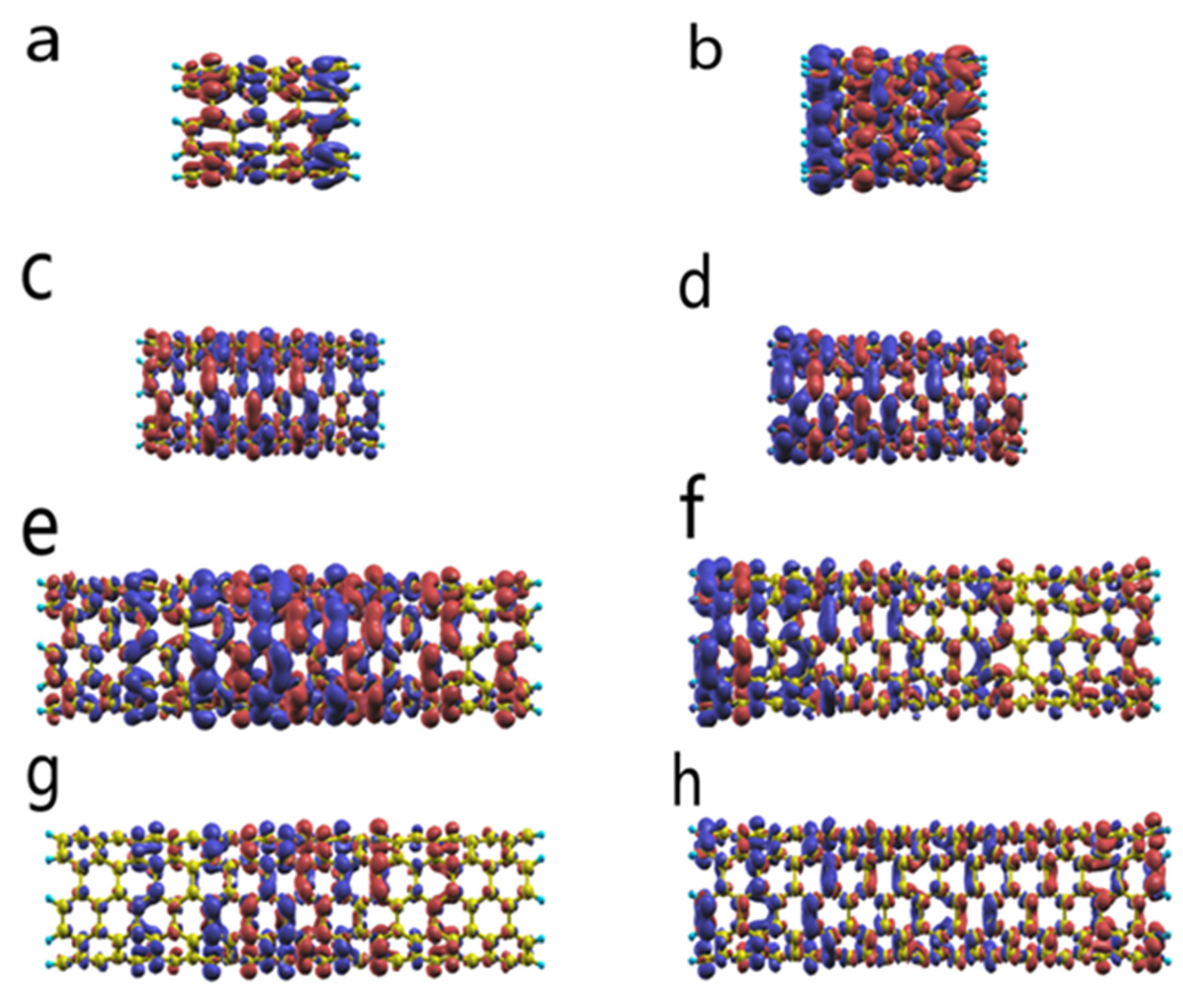
3.1.2. Electron Density Distribution of Intact CNT

To demonstrate the effect of an external field on the nonlinear optical properties of CNTs more clearly, we aim to model strong-field-driven electron dynamics in this hybrid system. As shown in Figure 4a–d, for short tubes C80H20 and C160H20, the distributions of induced electron density for ω 0 = 1.5 eV and 3.48 eV are similar. In these cases, the gradient of the near-field is difficult to represent due to the length limitation, and the intensity of the field is increased because of the Ag nanoparticles. So, the induced electron density is almost uniformly distributed on the carbon tube. As the tube length increases gradually, the polarization and rearrangement become more and more obvious. From Figure 4g,h, we can see that even in the absence of silver particles, the induced electron density distributions produced by light with different energies are different. For non-resonance cases, the induced electron density is mainly concentrated in the middle of the tube, indicating that the electrons in this part are more susceptible to being excited by the influence of an external field, whereas the electrons at the ends are hardly affected. But in the case of ω 0 = 3.48 eV, the induced electron density is almost uniformly distributed throughout the tube. Figure 4e demonstrates the distribution of induced electron density when ω 0 = 1.5 eV under the influence of silver nanoparticles. Compared to the case without silver nanoparticles, there is not much change in the distribution, except that more electron density can be induced due to the enhancement of the field. Since the distribution of the induced electron density is relatively localized, we did not find an obvious effect of the near-field gradient on it. When ω 0 = 3.48 eV, due to the significant gradients of the scattering field, from one end of the CNTs to the other, the strength of the external field decreases rapidly with distance. Figure 4f shows that for C260H20, the induced electron decreases with the direction of the weakening external field. Compared to the case without the presence of Ag nanoparticles, the enhancement effect is only manifested in the part closest to the metal surface and then decays rapidly. In the middle of the CNT and at the end, away from the metal nanoparticle, it is hardly seen. Instead, too-large gradients of the field prevent the dynamics of electrons in these sections. The rapidly decreasing induced electron density also explains why HHG does not increase with an increasing tube length at ω0 = 3.48 eV. It can be seen that the enhancement effect of metal nanoparticles can improve the efficiency of nonlinear spectrum generation. However, as the length of the carbon tubes increases, the excessive gradient of the near-field prevents further enhancement of the optical properties.

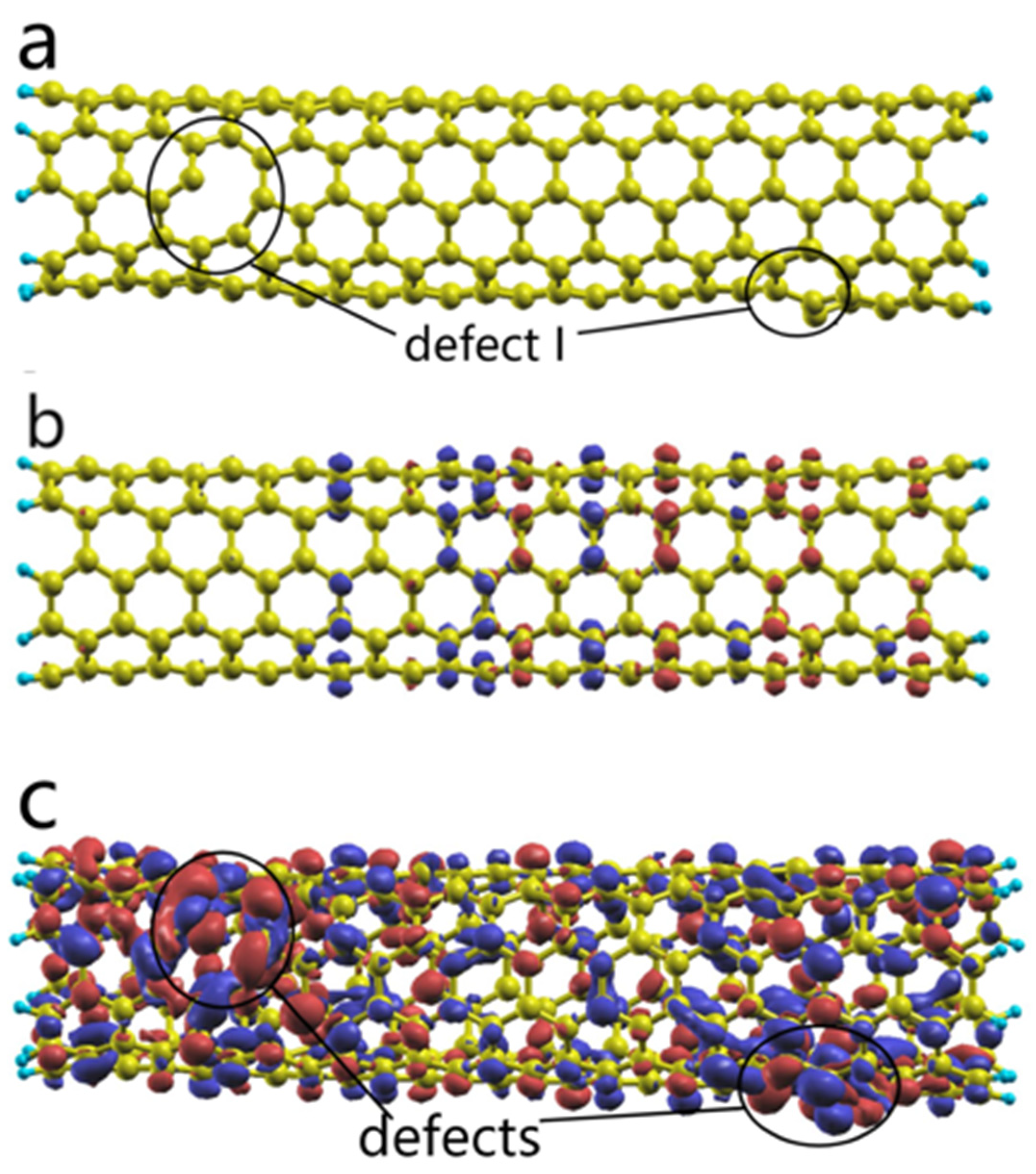
3.2. The HHG of Carbon Nanotubes with Defects

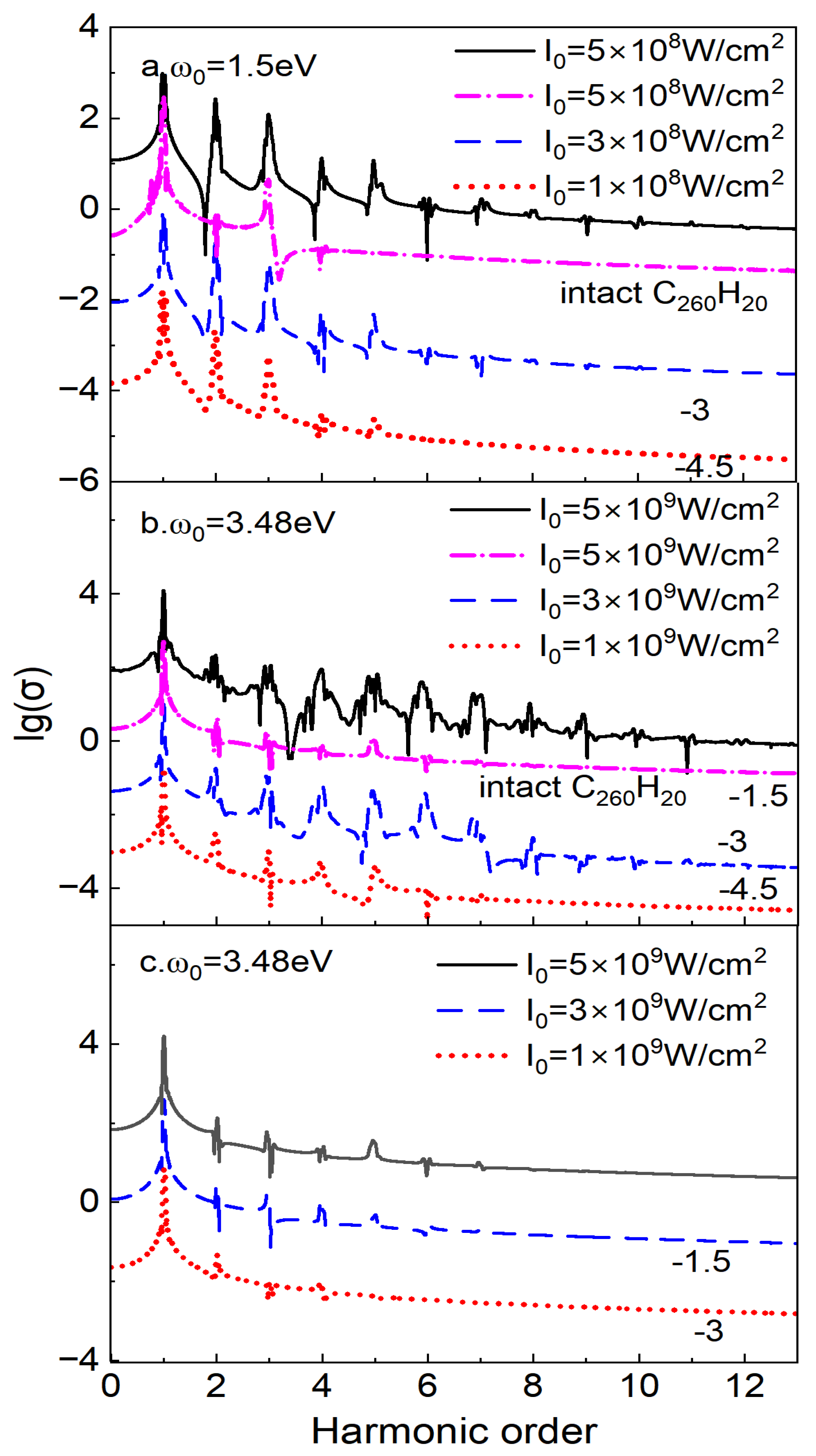
3.2.1. The Effect of Defects and Incident Field Intensity

Then, we investigate the effects of defects on the HHG of CNTs. In order to more closely approximate the properties of CNTs in solids, we will only discuss the long (5, 5) tube with a length of 3.269 nm. In this section, we remove two carbon atoms in C260H20, forming two oval-shaped vacancy defects that are asymmetrically distributed near the left and right ends of the CNT (see Figure 5a). And we call this oval-shaped defect defect I. The structure is also optimized using B3LYP/6-31G.
Figure 6 displays the surface-enhanced HHG of C258H20 and compares it with the HHG spectra of the intact CNT. This shows that the HHG is re-enhanced due to the very clear presence of the vacancy defects. The intensity of the HHG spectra increases, and the order also extends to a higher direction, whether ω 0 = 1.5 eV or 3.48 eV. As shown in Figure 6a, when ω 0 = 1.5 eV and, I 0 = 5 × 10 8   W/cm2 the highest order of HHG with vacancy defects is 10, which is 6 more than the highest order of HHG for intact CNTs. As shown in Figure 6b, when the light energy is 3.48 eV and the field strength is 5 × 10⁹ W/cm2, the highest order of HHG with vacancy defects is 11, which is 5 more than the highest order of HHG for complete CNTs. The intensity of the nonlinear optical spectra is related to hyperpolarizability. The first hyperpolarizability can be roughly represented by a two-level expression [72,73]:
β 0 9 × Δ μ × f 0 Δ E 3
where ∆μ, f0, and ∆E are the induced dipole moment, oscillator strength, and transition energy, respectively, and the effect of ∆E is the most significant. Without considering Ag NP, we study the excited states of C260H20 and C258H20 at the B3LYP/6-31G level. For intact CNTs, the first absorption peak is 1.24 eV. For C258H20, on the other hand, significant transitions occur in the excited states at 0.67 eV, 0.9 eV, and 1.13 eV. This shows that defects decrease the transition energy of systems, which may be an important factor in the enhancement of HHG [74].
This enhancement effect occurs due to the presence of vacancy defects, which can also be shown from the induced electronic density. Figure 5b depicts the induced electron density distribution of a complete carbon tube, and Figure 5c depicts the electron density distribution of a carbon nanotube with two vacancy defects. It is obvious that when the strength of the incident field is the same, the CNT with vacancy defects can excite more induced electrons. The added induced electron density is mainly distributed around the defects. This is in accordance with the conclusion that vacancy defects can increase the highest order of HHG. As we discussed in the previous section, for an intact CNT, the enhancement of HHG by silver spheres saturates or even diminishes with an increasing tube length and is affected by the field gradient. But the appearance of defects solves this problem and further enhances the HHG. This provides further possibilities for the regulation and wide application of HHG.
Then, we changed the intensity of the field to characterize the effect for CNTs with defects. As the strength of the incident field increases, the intensity of the HHG spectra increases, and the highest order also increases. So, at ω 0 = 1.5 eV, the highest-order difference of HHG is six as the field strength increases from 1 × 10⁸ W/cm2 to 5 × 10⁸ W/cm2. It is a little complicated when ω 0 = 3.48 eV. For intact CNTs, the effect of the increase in field strength is less pronounced. It can be explained in terms of the interference between the incident and scattered fields.
I 0 A 0 2 + A sca 2 + 2 A 0 A sca cos ( δ )
Here, A0 and Asca are the amplitudes of incident and scattered lights, respectively, and δ denotes the phase difference between those two light beams. In the resonance case, the phase difference between E0 and Esca is close to δ = π/2, and the coherence term in Equation (7) nearly disappears at ω 0 = 3.48 eV. As a result, for intact CNTs, when ω 0 = 3.48 eV, the HHG is not as sensitively affected by the strength of the external field. This can also be seen in Figure 6c. Obviously, the presence of defects solves this problem. We find that the HHG of defective CNTs is continuously enhanced by increasing the external field intensity. As Figure 6b shows, when the intensity of the external field changes from I 0 = 1 × 10⁹ W/cm2 to I 0 = 5 × 10⁹ W/cm2, the highest order of HHG grows from 7th to 12th. This suggests that the enhancement of optical properties due to vacancy defects is more susceptible to the intensities of the near-field.

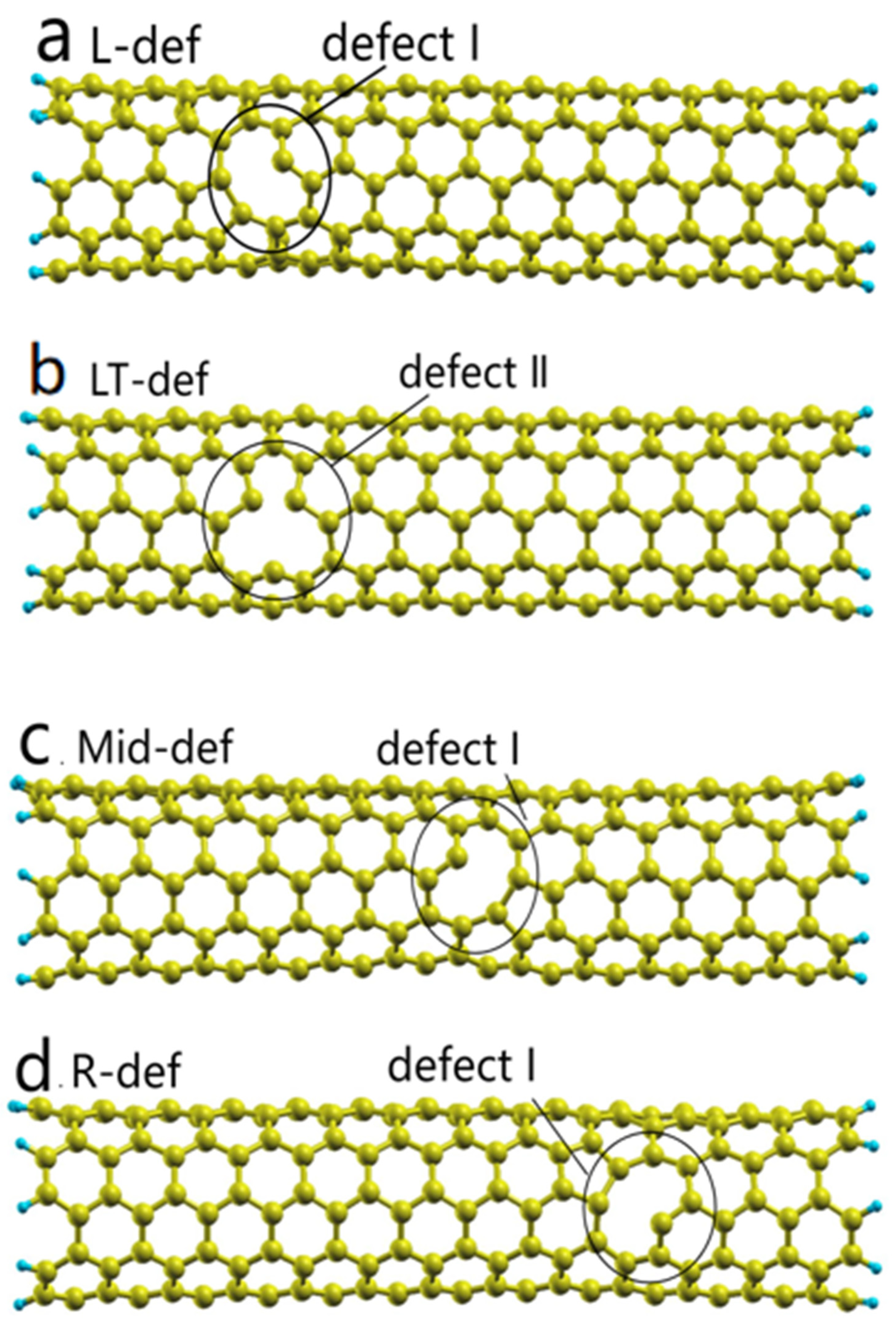
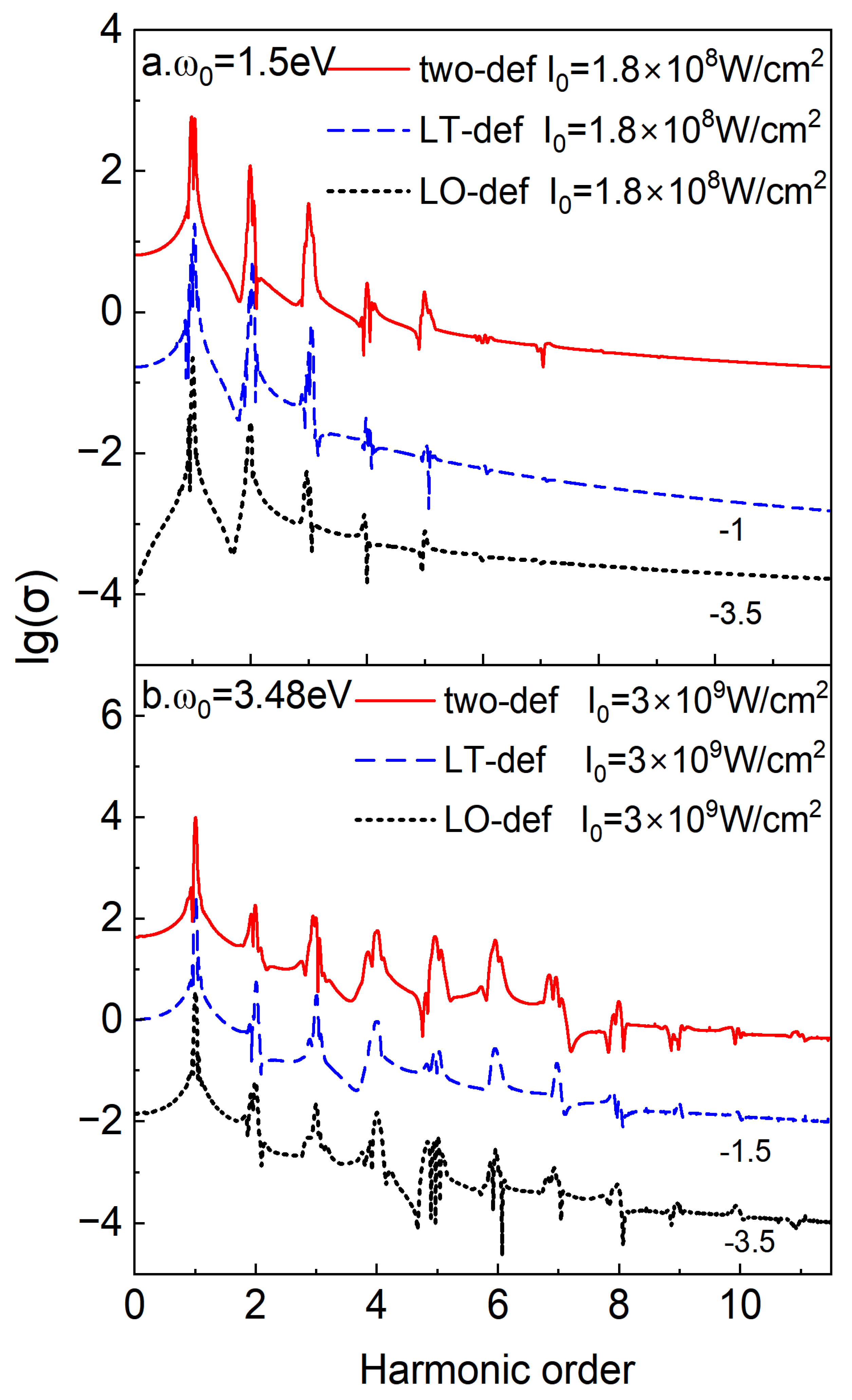
3.2.2. The Impact of the Shape and Number of Defects

In this section, the effect of the shape and number of defects on the nonlinear optical properties of the CNTs will be investigated. At first, we only preserved the left oval vacancy defect I (LO-def) in C259H20, as Figure 7a shows, to explore the influence of the number of defects on HHG. In the case of non-resonance, as shown in Figure 8a, the HHG with two vacancy defects is only one order more than the HHG with one vacancy defect at I 0 = 1.8 × 10 8 W/cm2. In the case of resonance, as shown in Figure 8b, no obvious differences in the HHG spectra of CNT with different numbers of defects at   I 0 = 3 × 10 9 W/cm2 were found. The increase in the number of defects did not result in a significant change in HHG, suggesting that there is an upper limit to the enhancement effect for nonlinear spectra. When saturation is reached, increasing the number of defects does not continue to increase the enhancement. However, since photons with an energy of 1.5 eV are more easily excited by electron absorption, it is harder to reach saturation than that of 3.48 eV. This is why the HHG spectra of the CNTs with two defects increase slightly at ω0 =1.5 eV, while at 3.48 eV, there is little change compared to CNTs with a single defect.
And then, on the same unit, we tried to move carbon atoms away at other positions, resulting in a triangular vacancy defect II (LT-def), as shown in Figure 7b. In the case of non-resonance, as shown in Figure 8a, it can be found that there is no significant difference in the HHG spectra of CNTs with different shapes of defect at I 0 = 1.8 × 10 8 W/cm2. The same phenomenon is also observed in the resonance case, as shown in Figure 8b. So, it can be shown that these two shapes of defects have no differences in the enhancement of the HHG spectra.

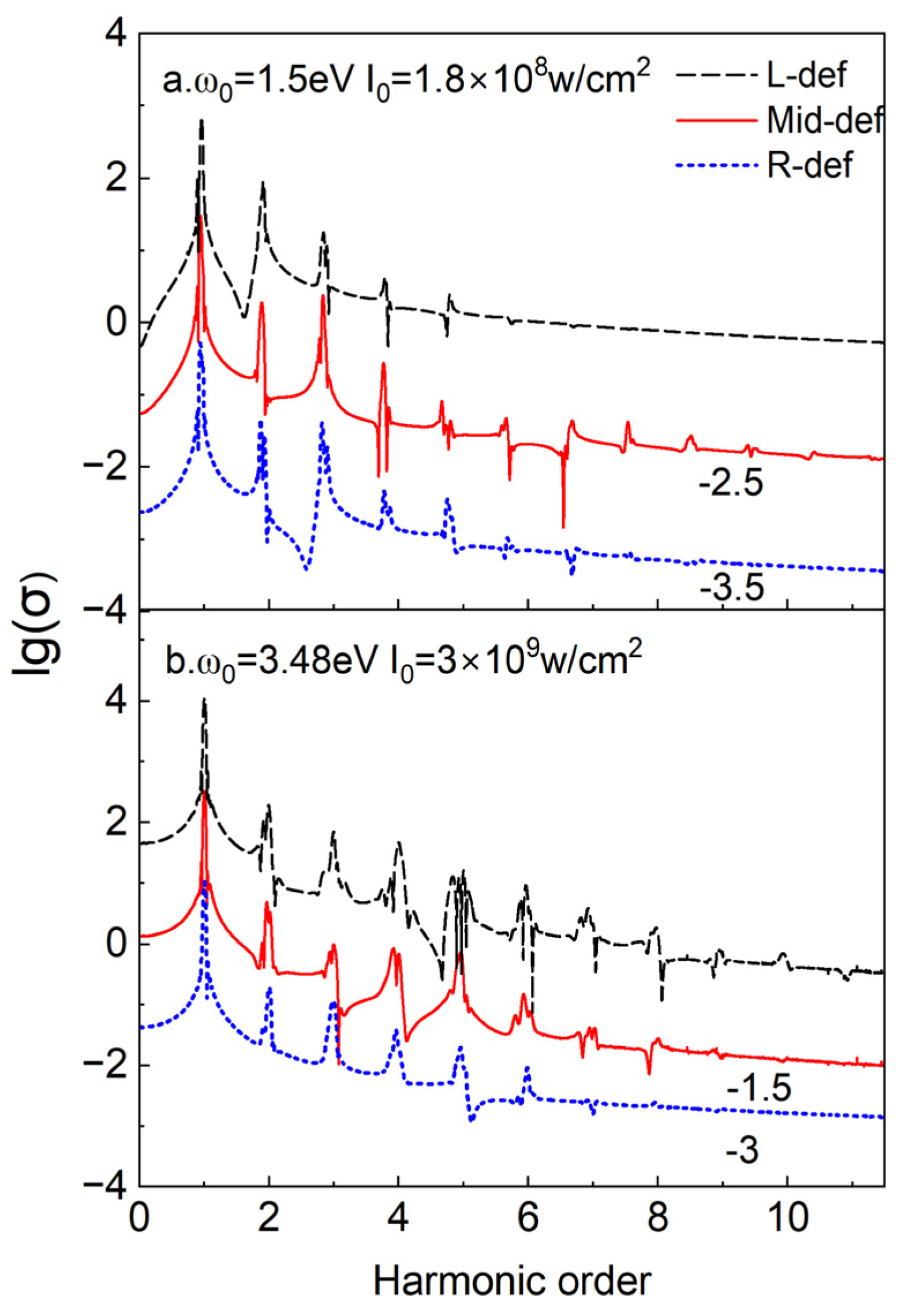
3.2.3. The Impact of Defect Location

We compared the HHG of CNTs with defects on the left (L-def), in the middle (Mid-def), and on the right (R-def), as shown in Figure 7a,c,d, to investigate the effect of the location of defects in a non-uniform field on the optical properties. In the case of non-resonance, when the defect moves from the left to the right, the distance between the defect and the surface of the metal nanoparticle increases, and the near-field intensity decreases gradually. But Figure 9a shows that the HHG with the defect in the middle is the strongest and has the highest order, which is due to the rearrangement of electrons in this case. For intact CNTs, at ω 0 = 1.5 eV, although the scattered field is non-uniform, the small gradient of the field does not play a significant role. So, most of the distribution of the induced electron density is not affected by the gradient force of the electric field and remains concentrated in the middle part of the tube (see Figure 4e). When there is a defect in the middle of the tube, increased induced electron density can be localized around the defect, which makes its enhancement effect for HHG the strongest (see Figure 10b). Conversely, if the defect is not in the middle of the tube, then the induced electrons will move toward the location of the defect. Figure 3 indicates that although the field strength interacting with the CNTs decreases from left to right, the change is not significant. Moreover, the farther away from the metal nanoparticles, the smaller the gradient of the scattering field. Near the right end of the carbon tube, the gradient of the scattering field is very small, and the total field is nearly uniform at ω 0 = 1.5 eV. If this is where the defect appears, the external field is likely to drive more induced electrons to cluster around the defects than in the case of defects on the left side of the CNTs, resulting in a better optical enhancement effect. The distribution of the induced electron density demonstrated in Figure 10a,c proves this point. So, the highest order of HHG concerning CNTs with defects on the right is a little more than the HHG of CNTs with defects on the left. This also suggests that the enhancement factor and gradient of the near-field have opposite effects and together influence the nonlinear optical properties. Thus, in the non-resonance case, the enhancement effect on the optical properties is most pronounced when the defects are in the middle of the CNTs, followed by the defects located at the end far away from the metal nanoparticles, and finally, the defects located at the end closest to the metal.
In the case of resonance, that is, ω 0 = 3.48 eV, the scattering field is very strong, but the gradient is also very large. As we discussed in a previous section, the influence of vacancy defects on HHG is more susceptible to the intensity of the near-field. Figure 9b shows that the HHG spectra decrease when the defect gradually moves from left to right because the strength of the field decreases quickly. The distribution of an induced electron density is also different due to the significant changes in the field strength at the location of the defect. Figure 10d–f shows that the vacancy defects on the left can produce more induced electron density due to their proximity to the metal nanoparticles. Then, for Mid-def and R-def, as the strength of the near-field decreases rapidly, the induced electron density decreases gradually, and thus the intensity of the HHG and the highest order that can occur also decrease. It follows that the intensity, gradient of the non-uniform scattering field, and location of the defects together affect the nonlinear optical properties of CNTs.

4. Conclusions

In this paper, the HHG spectra of H-terminated open-ended finite-sized (5, 5) CNTs with or without defects in the proximity of an Ag nanosphere of R = 5 nm were calculated using the hybrid TDHF/FDTD approach. To study HHG in solids, we investigated long CNTs with a length of 3.269 nm. We considered the effect of Ag NP on the nonlinear optical properties of CNTs through the inhomogeneous scattering field and ignored the back-action from the emitter to NP’s polarization. The influence of the energy of incident light and the gradient of the near-field on the nonlinear optical properties of intact CNTs was investigated at first. Then, we studied the effect of defects on CNTs, including the intensity of the external field, the number and shape of defects, and the location of defects on HHG spectra. The main conclusions are summarized as follows:
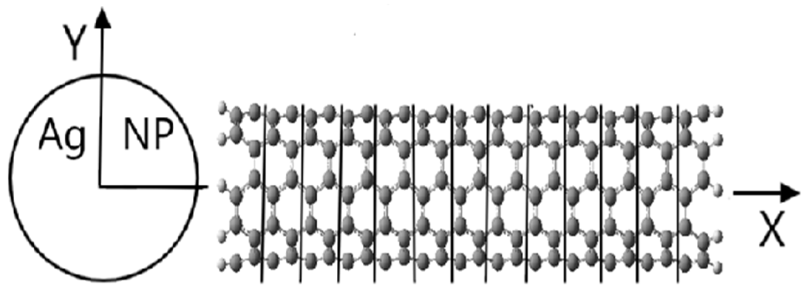
  • For intact CNTs, Ag NP will enhance the whole HHG. Due to the non-uniformity of the near-field, both odd and even orders of HHGs occur. But the nonlinear optical properties can be saturated when the tube length increases enough. The enhancement factor and gradient of the near-field have opposite effects on the nonlinear optical properties. When CNT is short, the enhancement factor of the near-field plays a major role for the HHG. If the incident field can resonate with the plasmon excitation, it will have a very good enhancement effect on the HHG due to the significant increase in the near-field. When the tube length increases enough, the role of near-field gradients is pronounced. In the resonance case, the gradient of the near-field is very large. It hinders the dynamics of electrons driven by the external field and leads to a rapid decrease in the induced electron density along the direction of the decreasing field strength. So, for long CNTs, metal nanoparticles can produce a more obvious enhancement of HHG in the non-resonance case.
  • The plasmon-enhanced HHG spectra of CNTs are re-enhanced and extended to a high energy range, very obviously by vacancy defects. This is because defects can reduce the transition energy of a system and generate more induced electron density. The enhancement of optical properties due to defects is more susceptible to the intensities of near-field.
  • When the frequency of the incident field does not resonate with the excitation of the AgNP, the plasmon-enhanced HHG can be enhanced by increasing the number of defects. However, the number of defects has little effect in the resonance case due to the excessively fast decay of the near-field. The shape of the vacancy defect also has little influence on the HHG spectra of CNTs.
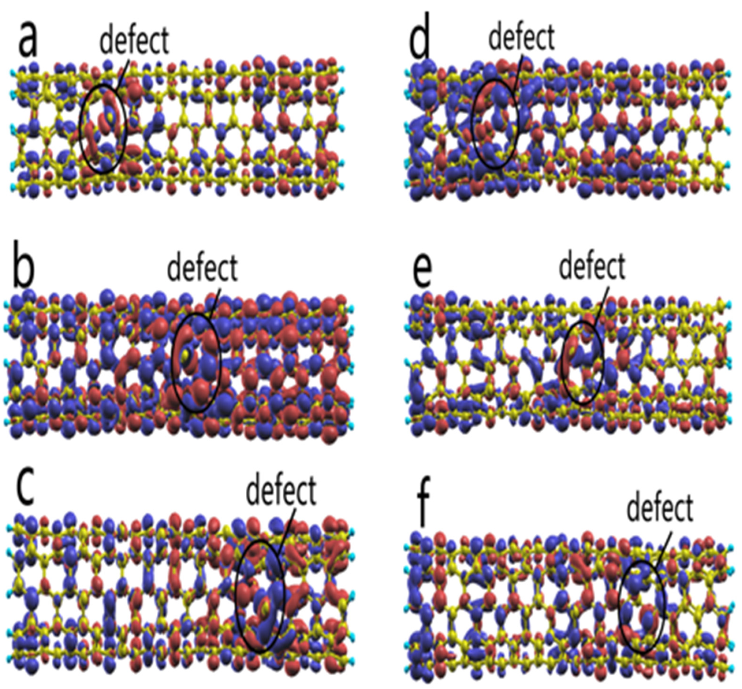
  • The location of defects can also have an effect on the plasmon-enhanced HHG due to the nonuniformity of the scattered field in the vicinity of Ag NP. In the resonance case, the distribution of the induced electron density is inhomogeneous due to the near-field gradient. It decreases gradually from the end close to the metal nanoparticles to the other end. So, as the defect moves from left to right, its enhancement effect on HHG also decreases. In the non-resonant case, the electric field gradient is small, and it is difficult to significantly affect the induced electrons. The defect is most effective at enhancing the nonlinear spectra if they occur in the middle of the tube, where a large number of induced electrons are originally distributed in the intact CNT. This is followed by defects appearing at the end, away from the metal nanoparticles, where there is little variation in the near-field.

Author Contributions

Conceptualization, J.S. and Z.D.; Data curation, Q.H. and J.S.; Formal analysis, Q.H., J.S. and Z.D.; Funding acquisition, J.S. and Z.D.; Investigation, Q.H., K.Y., Q.L., J.S. and Z.D.; Methodology, J.S.; Project administration, J.S.; Resources, Q.H., J.S. and Z.D.; Software, J.S.; Supervision, J.S. and Z.D.; Validation, Q.H., J.S. and Z.D.; Visualization, Q.H.; Writing—original draft, Q.H. and J.S.; Writing—review and editing, J.S. and Z.D. All authors have read and agreed to the published version of the manuscript.

Funding

This work was supported by the National Natural Science Foundation of China (21773001), the Anhui Project (Z010118169), and the Key Project of the Foundation of Anhui Education Committee, China (2022AH050066).

Data Availability Statement

The original contributions presented in the study are included in the article, further inquiries can be directed to the corresponding authors.

Conflicts of Interest

The authors declare no conflicts of interest.

References

  1. Haes, A.J.; Zou, S.; Schatz, G.C.; Van Duyne, R.P. Nanoscale Optical Biosensor: Short Range Distance Dependence of the Localized Surface Plasmon Resonance of Noble Metal Nanoparticles. J. Phys. Chem. B 2004, 108, 6961–6968. [Google Scholar] [CrossRef]
  2. Danckwerts, M.; Novotny, L. Optical Frequency Mixing at Coupled Gold Nanoparticles. Phys. Rev. Lett. 2007, 98, 026104. [Google Scholar] [CrossRef] [PubMed]
  3. Fofang, N.T.; Park, T.-H.; Neumann, O.; Mirin, N.A.; Nordlander, P.; Halas, N.J. Plexcitonic Nanoparticles: Plasmon−Exciton Coupling in Nanoshell−J-Aggregate Complexes. Nano Lett. 2008, 8, 3481–3487. [Google Scholar] [CrossRef] [PubMed]
  4. Lassiter, J.B.; Sobhani, H.; Fan, J.A.; Kundu, J.; Capasso, F.; Nordlander, P.; Halas, N.J. Fano Resonances in Plasmonic Nanoclusters: Geometrical and Chemical Tunability. Nano Lett. 2010, 10, 3184–3189. [Google Scholar] [CrossRef]
  5. Pelton, M.; Aizpurua, J.; Bryant, G. Metal-nanoparticle plasmonics. Laser Photon. Rev. 2008, 2, 136–159. [Google Scholar] [CrossRef]
  6. Shegai, T.; Li, Z.; Dadosh, T.; Zhang, Z.; Xu, H.; Haran, G. Managing light polarization via plasmon–molecule interactions within an asymmetric metal nanoparticle trimer. Proc. Natl. Acad. Sci. USA 2008, 105, 16448–16453. [Google Scholar] [CrossRef] [PubMed]
  7. Kim, Y.S.; Leung, P.; George, T.F. Classical decay rates for molecules in the presence of a spherical surface: A complete treatment. Surf. Sci. 1988, 195, 1–14. [Google Scholar] [CrossRef]
  8. Mertens, H.; Koenderink, A.F.; Polman, A. Plasmon-enhanced luminescence near noble-metal nanospheres: Comparison of exact theory and an improved Gersten and Nitzan model. Phys. Rev. B 2007, 76, 115123. [Google Scholar] [CrossRef]
  9. Guzatov, D.V.; Vaschenko, S.V.; Stankevich, V.V.; Lunevich, A.Y.; Glukhov, Y.F.; Gaponenko, S.V. Plasmonic Enhancement of Molecular Fluorescence near Silver Nanoparticles: Theory, Modeling, and Experiment. J. Phys. Chem. C 2012, 116, 10723–10733. [Google Scholar] [CrossRef]
  10. Fleischmann, M.; Hendra, P.J.; McQuillan, A.J. Raman spectra of pyridine adsorbed at a silver electrode. Chem. Phys. Lett. 1974, 26, 163–166. [Google Scholar] [CrossRef]
  11. Jeanmaire, D.L.; Van Duyne, R.P. Surface raman spectroelectrochemistry: Part I. Heterocyclic, aromatic, and aliphatic amines adsorbed on the anodized silver electrode. J. Electroanal. Chem. Interfacial Electrochem. 1977, 84, 1–20. [Google Scholar] [CrossRef]
  12. McPherson, A.; Gibson, G.; Jara, H.; Johann, U.; Luk, T.S.; McIntyre, I.A.; Boyer, K.; Rhodes, C.K. Studies of multiphoton production of vacuum-ultraviolet radiation in the rare gases. J. Opt. Soc. Am. B 1987, 4, 595–601. [Google Scholar] [CrossRef]
  13. Corkum, P.B.; Krausz, F. Attosecond science. Nat. Phys. 2007, 3, 381–387. [Google Scholar] [CrossRef]
  14. Krausz, F.; Ivanov, M. Attosecond physics. Rev. Mod. Phys. 2009, 81, 163–234. [Google Scholar] [CrossRef]
  15. Cavalieri, A.L.; Müller, N.; Uphues, T.; Yakovlev, V.S.; Baltuška, A.; Horvath, B.; Schmidt, B.; Blümel, L.; Holzwarth, R.; Hendel, S.; et al. Attosecond spectroscopy in condensed matter. Nature 2007, 449, 1029–1032. [Google Scholar] [CrossRef]
  16. Ghimire, S.; Reis, D.A. High-harmonic generation from solids. Nat. Phys. 2019, 15, 10–16. [Google Scholar] [CrossRef]
  17. Zaks, B.; Liu, R.B.; Sherwin, M.S. Experimental observation of electron–hole recollisions. Nature 2012, 483, 580–583. [Google Scholar] [CrossRef] [PubMed]
  18. Schubert, O.; Hohenleutner, M.; Langer, F.; Urbanek, B.; Lange, C.; Huttner, U.; Golde, D.; Meier, T.; Kira, M.; Koch, S.W.; et al. Sub-cycle control of terahertz high-harmonic generation by dynamical Bloch oscillations. Nat. Photon. 2014, 8, 119–123. [Google Scholar] [CrossRef]
  19. Vampa, G.; Hammond, T.J.; Thiré, N.; Schmidt, B.E.; Légaré, F.; McDonald, C.R.; Brabec, T.; Corkum, P.B. Linking high harmonics from gases and solids. Nature 2015, 522, 462–464. [Google Scholar] [CrossRef]
  20. Hohenleutner, M.; Langer, F.; Schubert, O.; Knorr, M.; Huttner, U.; Koch, S.W.; Kira, M.; Huber, R. Real-time observation of interfering crystal electrons in high-harmonic generation. Nature 2015, 523, 572–575. [Google Scholar] [CrossRef]
  21. Luu, T.T.; Garg, M.; Kruchinin, S.Y.; Moulet, A.; Hassan, M.T.; Goulielmakis, E. Extreme ultraviolet high-harmonic spectroscopy of solids. Nature 2015, 521, 498–502. [Google Scholar] [CrossRef] [PubMed]
  22. Ndabashimiye, G.; Ghimire, S.; Wu, M.; Browne, D.A.; Schafer, K.J.; Gaarde, M.B.; Reis, D.A. Solid-state harmonics beyond the atomic limit. Nature 2016, 534, 520–523. [Google Scholar] [CrossRef] [PubMed]
  23. You, Y.S.; Yin, Y.; Wu, Y.; Chew, A.; Ren, X.; Zhuang, F.; Gholam-Mirzaei, S.; Chini, M.; Chang, Z.; Ghimire, S. High-harmonic generation in amorphous solids. Nat. Commun. 2017, 8, 724. [Google Scholar] [CrossRef] [PubMed]
  24. Sivis, M.; Taucer, M.; Vampa, G.; Johnston, K.; Staudte, A.; Naumov, A.Y.; Villeneuve, D.M.; Ropers, C.; Corkum, P.B. Tailored semiconductors for high-harmonic optoelectronics. Science 2017, 357, 303–306. [Google Scholar] [CrossRef] [PubMed]
  25. Langer, F.; Schmid, C.P.; Schlauderer, S.; Gmitra, M.; Fabian, J.; Nagler, P.; Schüller, C.; Korn, T.; Hawkins, P.G.; Steiner, J.T.; et al. Lightwave valleytronics in a monolayer of tungsten diselenide. Nature 2018, 557, 76–80. [Google Scholar] [CrossRef]
  26. Lanin, A.A.; Stepanov, E.A.; Fedotov, A.B.; Zheltikov, A.M. Mapping the electron band structure by intraband high-harmonic generation in solids. Optica 2017, 4, 516–519. [Google Scholar] [CrossRef]
  27. Schuller, J.A.; Barnard, E.S.; Cai, W.; Jun, Y.C.; White, J.S.; Brongersma, M.L. Plasmonics for extreme light concentration and manipulation. Nat. Mater. 2010, 9, 193–204. [Google Scholar] [CrossRef]
  28. Kim, S.; Jin, J.; Kim, Y.-J.; Park, I.-Y.; Kim, Y.; Kim, S.-W. High-harmonic generation by resonant plasmon field enhancement. Nature 2008, 453, 757–760. [Google Scholar] [CrossRef]
  29. Tikman, Y.; Yavuz, I.; Ciappina, M.F.; Chacón, A.; Altun, Z.; Lewenstein, M. High-order-harmonic generation from Rydberg atoms driven by plasmon-enhanced laser fields. Phys. Rev. A 2016, 93, 023410. [Google Scholar] [CrossRef]
  30. Linnenbank, H.; Grynko, Y.; Förstner, J.; Linden, S. Second harmonic generation spectroscopy on hybrid plasmonic/dielectric nanoantennas. Light-Sci. Appl. 2016, 5, e16013. [Google Scholar] [CrossRef]
  31. Peng, L.-M.; Zhang, Z.; Wang, S. Carbon nanotube electronics: Recent advances. Mater. Today 2014, 17, 433–442. [Google Scholar] [CrossRef]
  32. Wang, C.; Takei, K.; Takahashi, T.; Javey, A. Carbon nanotube electronics—Moving forward. Chem. Soc. Rev. 2013, 42, 2592–2609. [Google Scholar] [CrossRef] [PubMed]
  33. De Volder, M.F.L.; Tawfick, S.H.; Baughman, R.H.; Hart, A.J. Carbon nanotubes: Present and future commercial applications. Science 2013, 339, 535–539. [Google Scholar] [CrossRef] [PubMed]
  34. Avouris, P.; Chen, Z.; Perebeinos, V. Carbon-based electronics. Nat. Nanotechnol. 2007, 2, 605–615. [Google Scholar] [CrossRef]
  35. Anantram, M.P.; Léonard, F. Physics of carbon nanotube electronic devices. Rep. Prog. Phys. 2006, 69, 507–561. [Google Scholar] [CrossRef]
  36. Popov, V.N. Carbon nanotubes: Properties and application. Mater. Sci. Eng. R Rep. 2004, 43, 61–102. [Google Scholar] [CrossRef]
  37. Baughman, R.H.; Zakhidov, A.A.; de Heer, W.A. Carbon Nanotubes—The Route Toward Applications. Science 2002, 297, 787–792. [Google Scholar] [CrossRef] [PubMed]
  38. Bellucci, S. Physical Properties of Ceramic and Carbon Nanoscale Structures; Springer: Heidelberg, Germany, 2011. [Google Scholar]
  39. Sun, J.; Ding, Z.; Yu, Y.; Liang, W. Plasmon-enhanced high order harmonic generation of open-ended finite-sized carbon nanotubes: The effects of incident field’s intensity and frequency and the interference between the incident and scattered fields. J. Chem. Phys. 2020, 152, 224708. [Google Scholar] [CrossRef]
  40. Dai, H.; Wong, E.W.; Lieber, C.M. Probing Electrical Transport in Nanomaterials: Conductivity of Individual Carbon Nanotubes. Science 1996, 272, 523–526. [Google Scholar] [CrossRef]
  41. Rodriguez-Manzo, J.A.; Banhart, F. Creation of Individual Vacancies in Carbon Nanotubes by Using an Electron Beam of 1 Å Diameter. Nano Lett. 2009, 9, 2285–2289. [Google Scholar] [CrossRef]
  42. Zadeh, Z.E.; Yadollahpour, M.; Ziaei-Rad, S.; Karimzadeh, F. The effect of vacancy defects and temperature on fundamental frequency of single walled carbon nanotubes. Comput. Mater. Sci. 2012, 63, 12–19. [Google Scholar] [CrossRef]
  43. Joshi, A.Y.; Sharma, S.C.; Harsha, S. The effect of pinhole defect on vibrational characteristics of single walled carbon nanotube. Phys. E Low-Dimens. Syst. Nanostruct. 2011, 43, 1040–1045. [Google Scholar] [CrossRef]
  44. Howlader, A.H.; Islam, S.; Tanaka, S.; Makino, T.; Hashimoto, A. Vacancy and curvature effects on the phonon properties of single wall carbon nanotube. Jpn. J. Appl. Phys. 2018, 57, 02CB08. [Google Scholar] [CrossRef]
  45. Kürti, J.; Zólyomi, V.; Grüneis, A.; Kuzmany, H. Double resonant Raman phenomena enhanced by van Hove singularities in single-wall carbon nanotubes. Phys. Rev. B 2002, 65, 165433. [Google Scholar] [CrossRef]
  46. Abdelkader, S.A.; Boutahir, M.; Rahmani, A.H.; Fakrach, B.; Bentaleb, M.; Chadli, H. Raman spectroscopy analysis of single wall carbon nanotubes with penta- and hexa-vacancies defects. IOP Conf. Ser. Mater. Sci. Eng. 2020, 783, 012014. [Google Scholar] [CrossRef]
  47. Saidi, W.A.; Norman, P. Spectroscopic signatures of topological and diatom-vacancy defects in single-walled carbon nanotubes. Phys. Chem. Chem. Phys. 2014, 16, 1479–1486. [Google Scholar] [CrossRef] [PubMed]
  48. Wright, L.B.; Rodger, P.M.; Corni, S.; Walsh, T.R. GolP-CHARMM: First-Principles Based Force Fields for the Interaction of Proteins with Au(111) and Au(100). J. Chem. Theory Comput. 2013, 9, 1616–1630. [Google Scholar] [CrossRef]
  49. Smith, H.T.; Karam, T.E.; Haber, L.H.; Lopata, K. Capturing Plasmon–Molecule Dynamics in Dye Monolayers on Metal Nanoparticles Using Classical Electrodynamics with Quantum Embedding. J. Phys. Chem. C 2017, 121, 16932–16942. [Google Scholar] [CrossRef]
  50. Fregoni, J.; Granucci, G.; Coccia, E.; Persico, M.; Corni, S. Manipulating azobenzene photoisomerization through strong light–molecule coupling. Nat. Commun. 2018, 9, 4688. [Google Scholar] [CrossRef]
  51. Mennucci, B.; Corni, S. Multiscale modelling of photoinduced processes in composite systems. Nat. Rev. Chem. 2019, 3, 315–330. [Google Scholar] [CrossRef]
  52. Chen, H.; McMahon, J.M.; Ratner, M.A.; Schatz, G.C. Classical Electrodynamics Coupled to Quantum Mechanics for Calculation of Molecular Optical Properties: A RT-TDDFT/FDTD Approach. J. Phys. Chem. C 2010, 114, 14384–14392. [Google Scholar] [CrossRef]
  53. Yam, C.; Meng, L.; Chen, G.; Chen, Q.; Wong, N. Multiscale quantum mechanics/electromagnetics simulation for electronic devices. Phys. Chem. Chem. Phys. 2011, 13, 14365–14369. [Google Scholar] [CrossRef] [PubMed]
  54. Meng, L.; Yam, C.; Koo, S.; Chen, Q.; Wong, N.; Chen, G. Dynamic Multiscale Quantum Mechanics/Electromagnetics Simulation Method. J. Chem. Theory Comput. 2012, 8, 1190–1199. [Google Scholar] [CrossRef] [PubMed]
  55. Payton, J.L.; Morton, S.M.; Moore, J.E.; Jensen, L. A Hybrid Atomistic Electrodynamics–Quantum Mechanical Approach for Simulating Surface-Enhanced Raman Scattering. Accounts Chem. Res. 2014, 47, 88–99. [Google Scholar] [CrossRef] [PubMed]
  56. Sun, J.; Li, G.; Liang, W. How does the plasmonic enhancement of molecular absorption depend on the energy gap between molecular excitation and plasmon modes: A mixed TDDFT/FDTD investigation. Phys. Chem. Chem. Phys. 2015, 17, 16835–16845. [Google Scholar] [CrossRef] [PubMed]
  57. Purcell, T.A.R.; Seideman, T. Modeling the Chiral Imprinting Response of Oriented Dipole Moments on Metal Nanostructures. ACS Photon. 2018, 5, 4801–4809. [Google Scholar] [CrossRef]
  58. Miller, E. Time-domain modeling in electromagnetics. J. Electromagn. Waves Appl. 1994, 8, 1125–1172. [Google Scholar] [CrossRef]
  59. Zerner, M.C.; Loew, G.H.; Kirchner, R.F.; Mueller-Westerhoff, U.T. An intermediate neglect of differential overlap technique for spectroscopy of transition-metal complexes. Ferrocene. J. Am. Chem. Soc. 1980, 102, 589–599. [Google Scholar] [CrossRef]
  60. McMahon, J.M.; Wang, Y.; Sherry, L.J.; Van Duyne, R.P.; Marks, L.D.; Gray, S.K.; Schatz, G.C. Correlating the Structure, Optical Spectra, and Electrodynamics of Single Silver Nanocubes. J. Phys. Chem. C 2009, 113, 2731–2735. [Google Scholar] [CrossRef]
  61. Ziman, J.M. Principles of the Theory of Solids, 2nd ed.; Cambridge University Press: Cambridge, UK, 1972. [Google Scholar] [CrossRef]
  62. Piela, L. The Molecule Subject to the Electric or Magnetic Field. In Ideas of Quantum Chemistry; Elsevier: Amsterdam, The Netherlands, 2014; pp. 719–792. [Google Scholar] [CrossRef]
  63. Sundaram, B.; Milonni, P.W. High-order harmonic generation: Simplified model and relevance of single-atom theories to experiment. Phys. Rev. A 1990, 41, 6571–6573. [Google Scholar] [CrossRef]
  64. Sun, J.; Guo, Z.; Liang, W. Harmonic generation of open-ended and capped carbon nanotubes investigated by time-dependent Hartree-Fock theory. Phys. Rev. B 2007, 75, 195438. [Google Scholar] [CrossRef]
  65. Sun, J.; Song, J.; Zhao, Y.; Liang, W.-Z. Real-time propagation of the reduced one-electron density matrix in atom-centered Gaussian orbitals: Application to absorption spectra of silicon clusters. J. Chem. Phys. 2008, 127, 234107. [Google Scholar] [CrossRef] [PubMed]
  66. Sun, J.; Liu, J.; Liang, W.; Zhao, Y. Real-Time Propagation of the Reduced One-Electron Density Matrix in Atom-Centered Orbitals: Application to Multielectron Dynamics of Carbon Clusters Cn in the Strong Laser Pulses. J. Phys. Chem. A 2008, 112, 10442–10447. [Google Scholar] [CrossRef]
  67. Wang, F.; Yam, C.Y.; Chen, G.; Fan, K. Density matrix based time-dependent density functional theory and the solution of its linear response in real time domain. J. Chem. Phys. 2007, 126, 244102. [Google Scholar] [CrossRef] [PubMed]
  68. Castro, A.; Marques, M.A.L.; Rubio, A. Propagators for the time-dependent Kohn–Sham equations. J. Chem. Phys. 2004, 121, 3425–3433. [Google Scholar] [CrossRef]
  69. Cheng, C.-L.; Evans, J.S.; Van Voorhis, T. Simulating molecular conductance using real-time density functional theory. Phys. Rev. B 2006, 74, 155112. [Google Scholar] [CrossRef]
  70. Gieseking, R.L.; Ratner, M.A.; Schatz, G.C. Semiempirical Modeling of Ag Nanoclusters: New Parameters for Optical Property Studies Enable Determination of Double Excitation Contributions to Plasmonic Excitation. J. Phys. Chem. A 2016, 120, 4542–4549. [Google Scholar] [CrossRef]
  71. Ganeev, R.A.; Naik, P.A.; Singhal, H.; Chakera, J.A.; Kumar, M.; Joshi, M.P.; Srivastava, A.K.; Gupta, P.D. High-order harmonic generation in carbon-nanotube-containing plasma plumes. Phys. Rev. A 2011, 83, 013820. [Google Scholar] [CrossRef]
  72. Kanis, D.R.; Ratner, M.A.; Marks, T.J. Design and construction of molecular assemblies with large second-order optical nonlinearities. Quantum chemical aspects. Chem. Rev. 1994, 94, 195–242. [Google Scholar] [CrossRef]
  73. Oudar, J.L.; Chemla, D.S. Hyperpolarizabilities of the nitroanilines and their relations to the excited state dipole moment. J. Chem. Phys. 1977, 66, 2664–2668. [Google Scholar] [CrossRef]
  74. Liu, Z.-B.; Zhou, Z.-J.; Li, Z.-R.; Li, Q.-Z.; Jia, F.-Y.; Cheng, J.-B.; Sun, C.-C. What is the role of defects in single-walled carbon nanotubes for nonlinear optical property? J. Mater. Chem. 2011, 21, 8905–8910. [Google Scholar] [CrossRef]
Figure 1. The simulation diagram of the hybrid system.
Crystals 14 00115 g001
Figure 2. The plasmon−enhanced HHG spectra of intact CNTs with tube lengths of 3.269 nm, 2.033 nm, and 1.046 nm at (a) ω 0 = 1.5   eV, I 0 = 5 × 10 9   W/cm2; (b) ω 0 = 3.48   eV, I 0 = 5 × 10 9   W/cm2. The inset is the HHG spectra of intact CNTs without silver nanoparticles and with tube lengths of 3.269 nm vary with ω 0 at I 0 = 1 × 10 10   W/cm2.
Crystals 14 00115 g002
Figure 3. The enhanced ratio of near-field varies with the distance between the NP’s surface and the observed point along the x axis and ω 0 .
Crystals 14 00115 g003
Figure 4. The induced electron density of CNT close to the Ag sphere: (a,b) C80H20 at ω 0 = 1.5   eV and   ω 0 = 3.48   eV , respectively; (c,d) C160H20 at ω 0 = 1.5   eV and   ω 0 = 3.48   eV , respectively; (e,f) C260H20 at ω 0 = 1.5   eV and   ω 0 = 3.48   eV (g,h) the induced electron density of C260H20 in the homogeneous field without Ag sphere at ω 0 = 1.5   eV and   ω 0 = 3.48   eV . All induced electron densities are drawn when the field strength is near its maximum.
Crystals 14 00115 g004
Figure 5. (a) The structure of CNT with two defects, C258H20; (b,c) the distribution of the induced electron density of an intact CNT (C260H20) and defective CNT (C258H20) at ω 0 = 1.5   eV, I 0 = 5 × 10 8   W/cm2.
Crystals 14 00115 g005
Figure 6. The plasmon-enhanced HHG spectra of CNT (C258H20) with the absence of two carbon atoms vary with I0 at (a) ω 0 = 1.5   eV; and (b) ω 0 = 3.48   eV. (c) The HHG spectra of intact CNT vary with I0 at ω 0 = 3.48   eV.
Crystals 14 00115 g006
Figure 7. (a) The CNT with an oval defect I on the left (LO−def). (b) The CNT with a triangular defect II on the left (LT−def). (c) The CNT with an oval defect I in the middle (Mid-def). (d) The CNT with an oval defect I on the right (R-def).
Crystals 14 00115 g007
Figure 8. The HHG of CNT with two defects, one left triangular defect (LT−def) or one left oval defect (LO−def) at (a) ω 0 = 1.5   eV , I 0 = 1.8 × 10 8   W / cm 2 ; (b), I 0 = 3 × 10 9   W / cm 2 .
Crystals 14 00115 g008
Figure 9. The plasmon−enhanced HHG spectra of C259H20 with the absence of carbon atoms on the left, in the middle, and on the right at (a) ω 0 = 1.5   eV, I 0 = 1.8 × 10 8 W/cm2 and (b)   ω 0 = 3.48   eV, I 0 = 3 × 10 9 W/cm2.
Crystals 14 00115 g009
Figure 10. Distribution of the induced electron density of C259H20 close to the Ag sphere: (ac) defects on the left, center, and right side of CNTs, respectively, ω 0 = 1.5   eV and I 0 = 1.8 × 10 8 W/cm2; (df) defects on the left, center, and right side of CNTs, respectively, ω 0 = 3.48   eV,   I 0 = 3 × 10 9   W / cm 2 .
Crystals 14 00115 g010
Disclaimer/Publisher’s Note: The statements, opinions and data contained in all publications are solely those of the individual author(s) and contributor(s) and not of MDPI and/or the editor(s). MDPI and/or the editor(s) disclaim responsibility for any injury to people or property resulting from any ideas, methods, instructions or products referred to in the content.

