Article

Anisotropic Mechanical and Microstructural Properties of a Ti-6Al-7Nb Alloy for Biomedical Applications Manufactured via Laser Powder Bed Fusion

1
Chair of Materials Science (LWK), Paderborn University, Warburger Straße 100, 33098 Paderborn, Germany
2
Institute for Lightweight Design with Hybrid Systems (ILH), Paderborn University, Mersinweg 7, 33100 Paderborn, Germany
*
Author to whom correspondence should be addressed.
Crystals 2024, 14(2), 117; https://doi.org/10.3390/cryst14020117
Submission received: 19 December 2023 / Revised: 16 January 2024 / Accepted: 22 January 2024 / Published: 24 January 2024
(This article belongs to the Section Crystalline Metals and Alloys)

Abstract

:
Through tailoring the geometry and design of biomaterials, additive manufacturing is revolutionizing the production of metallic patient-specific implants, e.g., the Ti-6Al-7Nb alloy. Unfortunately, studies investigating this alloy showed that additively produced samples exhibit anisotropic microstructures. This anisotropy compromises the mechanical properties and complicates the loading state in the implant. Moreover, the minimum requirements as specified per designated standards such as ISO 5832-11 are not met. The remedy to this problem is performing a conventional heat treatment. As this route requires energy, infrastructure, labor, and expertise, which in turn mean time and money, many of the additive manufacturing benefits are negated. Thus, the goal of this work was to achieve better isotropy by applying only adapted additive manufacturing process parameters, specifically focusing on the build orientations. In this work, samples orientated in 90°, 45°, and 0° directions relative to the building platform were manufactured and tested. These tests included mechanical (tensile and fatigue tests) as well as microstructural analyses (SEM and EBSD). Subsequently, the results of these tests such as fractography were correlated with the acquired mechanical properties. These showed that 90°-aligned samples performed best under fatigue load and that all requirements specified by the standard regarding monotonic load were met.

1. Introduction

The revolutionary technology of additive manufacturing (AM) enables the fabrication of high-performance parts with complex geometries, high accuracy, and minimum lead time. All these features are achieved by just using a tool-free and iterative layer-by-layer manufacturing approach [1]. These features increase the attractiveness of AM in various industries such as aerospace, automotive, and biomedical [2,3,4]. Luckily, different types of AM exist, e.g., direction energy deposition (DED) and laser powder bed fusion (PBF-LB/M), just to name two of them. While the former is used in different industries, it has some limitations such as dimensional accuracy, while the latter is more applicable in the manufacturing of metals. Accordingly, PBF-LB/M is a very promising and widely used technique for producing almost fully dense metal parts in applications where high dimensional accuracy and intricate geometries are required, for instance, additive leading edge aviation propulsion (LEAP) engine fuel nozzles that contributed to the increase in fuel efficiency [5,6,7,8]. This method includes different steps; first, thin layers of metal powder that range between 20 µm and 100 µm are deposited one by one onto a substrate. Before depositing the subsequent layer, each layer will first be selectively melted and fused by a high-energy laser that passes through the deposited layer. Then the following layer will be deposited and so on, until the desired shape is achieved [9]. During these steps, the applied high-energy laser penetrates each time into the material deeper than the thickness of the deposited layer; by that process, it will melt the most recently deposited layer and additionally remelt the layer that has been already melted in previous passes. These processes of melting and remelting are repeated many times over the building time of the part for each layer until these layers are obscured by the upper layers that were built more recently. When the laser cannot reach the deeper solidified layers, these layers cool down and act as heatsinks. Consequently, the multiple melting passes and the increased thermal mass lead to high thermal gradients and fast cooling rates between 105 K/s and 106 K/s [10,11]. Therefore, PBF-LB/M-processed materials, in contrast to conventional manufacturing processes and associated low cooling rates, exhibit a characteristic fine-grained microstructure, which, however, exhibits a characteristic anisotropy of mechanical properties and an increased solubility limit [12,13]. Thus, the nearly non-existent process limitations of PBF-LB/M in terms of available biomaterial alloys and high design freedom justify its utilization in biomedical applications, such as intravascular stents, orthopedic implants, and further surgically implanted artificial body parts [14,15]. Different titanium alloys are used as biomaterials, such as Ti-6Al-4V, Ti-6Al-7Nb, and Ti-29Nb-13Ta-4.6Zr. Among the previous alloys, the former—which was originally used as aerospace materials—is the most widely used alloy as a load bearing implant in dental and orthopedic surgery. Their application is justified by their high specific strength, low Young’s modulus, and excellent corrosion resistance, as well as excellent biocompatibility [16,17,18,19,20]. Nevertheless, due to the toxicity of the alloying elements aluminum (Al) and vanadium (V), previous studies established a decrease in their biocompatibility and increased toxicity [21,22,23,24]. Consequently, intensified efforts have been dedicated to developing new types of biocompatible α + β and β titanium-based alloys, e.g., Ti-6Al-7Nb, Ti-13Nb-13Zr, or Ti-35Nb-5Ta-7Zr. These alloys consist of partially or completely non-toxic elements such as niobium (Nb), zirconium (Zr), molybdenum (Mo), tantalum (Ta), and tungsten (Wo) [25,26]. Owing to their superior corrosion resistance, high mechanical properties, and higher biocompatibility in comparison with commonly used Ti-6Al-4V, in particular, Ti-6Al-7Nb alloys’ designed purpose was to be used in load-bearing implants [26,27,28]. Ti-6Al-7Nb belongs to α + β titanium alloys; in it, Al and Nb stabilize the hexagonal close-packed α phase as well as the body-centered cubic β phase and maintain an equilibrium α + β dual phase at ambient temperature [29]. Nevertheless, the phase transformation and associated mechanical properties of α + β titanium alloys strongly depend on the thermal history and cooling rates which are controlled by the manufacturing process [30,31]. Therefore, as different manufacturing methods result in different thermal cycles and histories, one expects the microstructure of these alloys to also depend on the employed manufacturing method. Indeed, PBF-LB/M-processed α + β alloys reveal the decomposition of the β phase by a non-equilibrium martensitic reaction due to rapid cooling from above the β-transus temperature [32]. This diffusionless reaction induces the formation of fine acicular α′ martensite contained within prior columnar β-grains elongated in the build direction [33,34,35]. This manufacturing-method-related microstructure causes the anisotropic mechanical behavior combined with high strength but unfortunately poor ductility in the as-built condition [36,37,38]. This is challenging since the required ductility in the related standards for wrought or cast titanium alloys in implant surgery is not met and restricts the use of this alloy in biomedical applications [39,40].
Despite their importance in biomedical applications, only a few previous studies have focused on the quasi-static and fatigue behavior of an α + β type Ti-6Al-7Nb alloy processed through PBF-LB/M [41,42,43,44,45,46]. Regarding anisotropy, only Chlebus et al. [41] examined the quasi-static mechanical properties of Ti-6Al-7Nb in the as-built condition compared with the wrought equivalent. Their results show a general improvement in the ultimate tensile strength with a reduction in ductility in the as-built condition. This was caused by the formation of hard and brittle α′-martensite in the microstructure. Moreover, significant anisotropic properties in strength and ductility persisted between vertically and horizontally built parts. In summary, these investigations were mostly performed concerning vertically and/or horizontally orientated built parts and revealed a significant gap of knowledge suggesting the necessity of examinations regarding off-axis mechanisms in the as-built state. Therefore, this study tries to bridge such a knowledge gap by evaluating the effect of different build orientations on microstructural and quasi-static as well as high-cycle fatigue (HCF) properties of PBF-LB/M-processed Ti-6Al-7Nb samples.

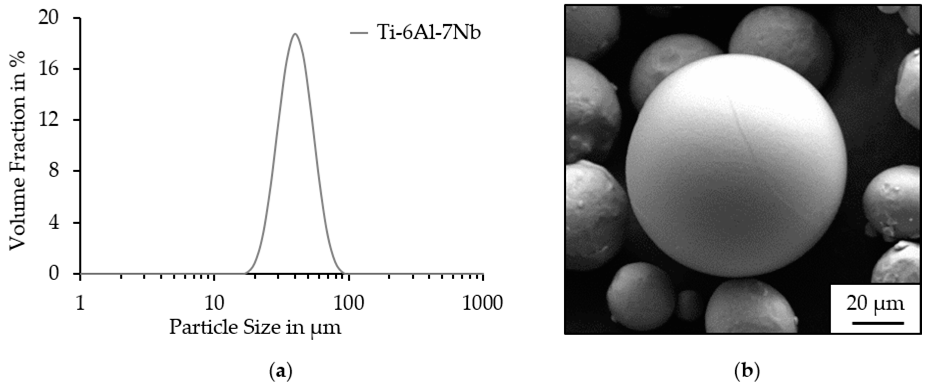
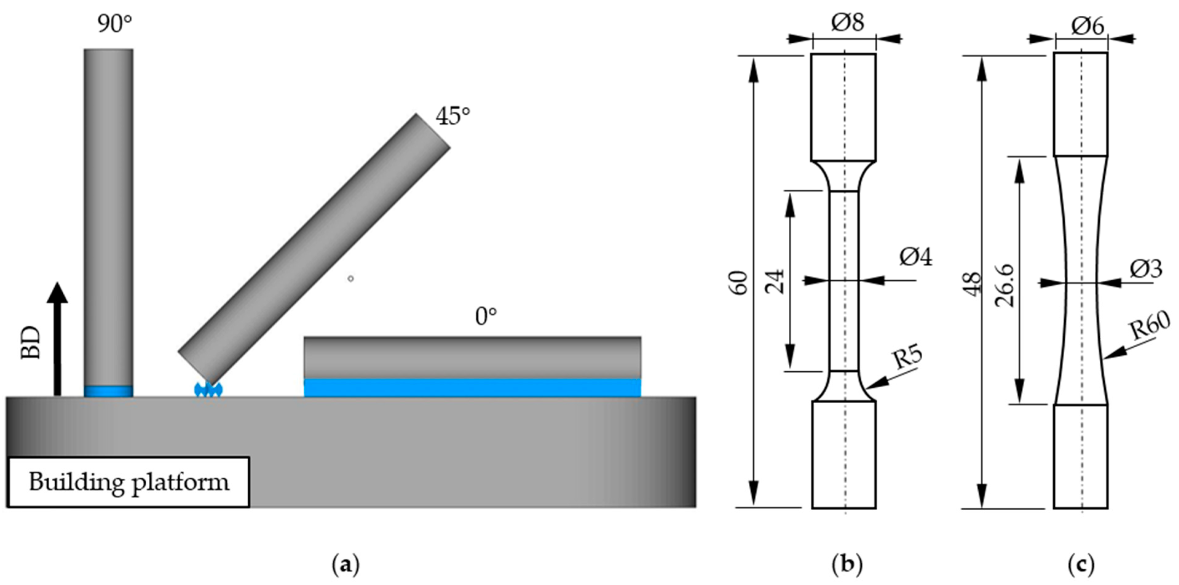
2. Materials and Methods

In this study, gas-atomized Ti-6Al-7Nb powder (Eckart TLS GmbH, Bitterfeld, Germany) was used. The powder particle size distribution (PSD) was determined using the Mastersizer 2000 (Malvern Panalytical GmbH, Kassel, Germany), which applied the laser diffraction method to measure the particle size. The results indicated a nominal PSD consisting of d10, 25.98 µm; d50, 37.43 µm; and d90, 53.81 µm (Figure 1a). To determine its morphology, this powder was examined with scanning electron microscopy (SEM). For that, the SEM Zeiss Ultra Plus (Carl Zeiss AG, Oberkochen, Germany) was used. The Ti-6Al-7Nb powder exhibited a predominantly spherical particle morphology with some satellites (Figure 1b).
The chemical composition was analyzed via inductively coupled plasma optical emission spectrometry (OES) with a Q4 TASMAN (Fa. Bruker AXS GmbH, Karlsruhe, Germany). For this, the top surface of the as-built cuboid (25 mm × 30 mm × 10 mm) was characterized. These results were compared with the chemical composition of the supplied powder. In the following, the results of both methods are compared with the standard composition as per standard ISO 5832-11 [40] (Table 1).
To determine the quasi-static and fatigue behavior, cylindrical specimens with two different dimensions were prepared (Ø 9 mm × 61 mm and Ø 7 mm × 49 mm). Before the manufacturing step, STL files were arranged using the software Magics 21 (Materialise GmbH, Munich, Germany). These samples were orientated at 90°, 45°, and 0° angles relative to the building platform (Figure 2a).
For manufacturing the samples, an LT12 SLM System (DMG Mori Additive GmbH, Bielefeld, Germany) was used. This machine was equipped with a modulated 400 W ytterbium fiber laser with a minimum beam spot size of 35 µm. All samples were built under a protective argon atmosphere with an oxygen content between 0.1% and 0.15%. The employed scanning strategy was a 10 mm stripes strategy. Each layer was scanned once with a subsequent layer-wise rotation of the scanning vectors by 31°. A preheated titanium platform was used (200 °C) and was kept constant at this temperature during the entire building process.
During manufacturing, the process parameters were optimized for maximum relative density so that the effects of porosity and lack of fusion either were kept to a minimum or could be excluded [47]. For this purpose, a process parameter configuration was selected in advance of this study by varying laser power and laser scanning speed, as well as hatch distance, and was subsequently evaluated on cubes with an edge length of 10 × 10 × 10 mm. After manufacturing, the cube surfaces were polished and analyzed using the Keyence VHX5000 light microscope (KEYENCE GmbH, Neu-Isenburg, Germany) for identifying a density-optimized process parameter. The optimized process parameter resulted in almost fully dense samples; a density of 99.99% was reached (Figure 3a and Table 2). Once the sample with the highest relative density was identified, a more detailed analysis was performed on the finished tensile specimens using Bruker’s SkyScan 1275 (Bruker Corporation, Billerica, MA, USA) X-ray-based desktop micro-CT scanner (μCT) with a source power of 10 W and a 1.0 mm copper filter. The specimens were analyzed with a rotation step of 0.4° and a voxel size of 6 μm. As µCT measurement is very time-consuming, a section of Ø 4 × 10 mm was analyzed in the measuring range of one tensile specimen per orientation. The results indicated a high relative density of above 99.98%, with the 45° and 90° tensile specimens showing a slightly higher number of pores (Figure 3b–d).
The built samples were cylindrical, which differed from tensile and HCF sample geometry according to DIN EN ISO 6892-1 [48] and DIN 50100 [49] (Figure 2b,c). Therefore, to acquire tensile and HCF samples with standard geometry, as-built samples underwent a post-processing turning step. For that, the CTX beta 800 TC milling and turning system (DMG Mori AG, Bielefeld, Germany) was used.
Microstructural observations were conducted on longitudinally sectioned tensile specimens that were parallel to the loading direction. For that, the samples were separated with a precision separating machine, the Struers Secotom-50 (Struers GmbH, Hannover, Germany), and the sample surface was ground with SiC abrasive paper up to 4000 grit. After that, the samples were vibration polished via VibroMet (Buehler, ITW Test & Measurement GmbH, Leinfelden-Echterdingen, Germany) for 12 h and etched with Kroll regent. For the microscopic examination, the etched samples were characterized using the light microscope Keyence VHX5000 (KEYENCE GmbH, Neu-Isenburg, Germany) and the scanning electron microscope (SEM) Zeis Ultra Plus (Carl Zeiss AG, Oberkochen Germany) equipped with an electron backscatter diffraction (EBSD) detector DIGIVIEW 5 (AMETEK, Berwyn, IL, USA). The EBSD data analysis regarding the reconstruction of prior β titanium grains was performed with a MATLAB-based (Version R2019a 9.6, The MathWorks, Inc., Natick, MA, USA) toolbox MTEX script (Version 5.8.1).
To investigate the influence of the build orientation, different mechanical tests were performed. The monotonic tensile tests were carried out using a two-axis MTS 810 servo-hydraulic testing system equipped with a 100 kN load cell system and an extensometer MTS Model 632.31F-24 with a gauge length of 20 mm (both MTS Systems Corporation, Eden Prairie, MN, USA). As per DIN EN ISO 6892-1 [48], three tensile specimens of each orientation were tested with a displacement-controlled crosshead speed of 0.05 mm‧s−1 and analyzed concerning the ultimate tensile strength (UTS) Rm, yield strength (YS) Rp0,2, and elongation at breakage (A), as well as the Young’s modulus (E).
HCF tests were performed as per DIN 50100 [49] on a high-frequency testing machine, ElectroForce 3550 (Bose Corporation Electro-Force Systems Group, Eden Prairie, MN, USA). These tests were conducted at room temperature with a stress ratio of R = −1 and a test frequency of 50 Hz. The fatigue life was limited by a maximum number of 107 cycles. For determining the fatigue behavior between finite-life long and long-life strength ranges, Wöhler tests were performed on three specimens at different stress amplitudes. The fatigue tests were terminated as soon as a specimen achieved 107 cycles without failing, and the average long-life fatigue strength was obtained iteratively using the staircase (SC) test method. All fatigue data were illustrated using an S–N diagram, showing the characteristic values.
The fracture surfaces of tensile and fatigue specimens were investigated by using an SEM to identify surface defects that could severely affect the mechanical properties. Secondary electrons (SE) and an in-lens detector were used to image the topography of the fracture surfaces.

3. Results and Discussion

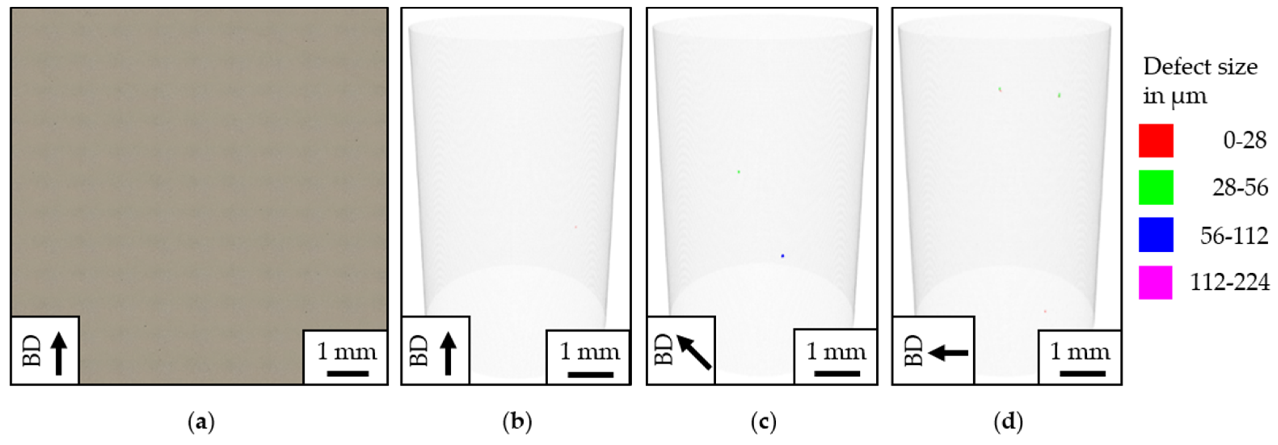
3.1. Microstructure Analysis

The performed light microscopy characterization is shown in Figure 4a–c. In them, different microstructural features expressed by various tones in the image are shown. These features were differently orientated—concerning the horizontal coordinate system—in such a way that they correlated to different extents with the build orientation. These feature grains were proven to be columnar β grains [50]. Interestingly, these grains, as shown in Figure 4a–c, extended over a couple of layers with a corresponding width equivalent to the hatch distance [51]. Given the PBF-LB/M layer-wise add-on approach, with a layer thickness of 50 µm, this could only be understood in terms of epitaxial growth ensuing from the preferred heat transfer flow dictated by local melting via laser beam [37,52]. Moreover, PBF-LB/M layer-wise scan rotation of 31° led to the displacement of weld overlap across several layers and resulted in an irregular arrangement of primary β grain boundaries (Figure 4a–c). The size and morphology of the prior β grains strongly depended on the process conditions affecting the thermal gradient contrary to the building direction [53,54]. Interestingly, within β grains existed fine-grained lath-like features. Their presence was confirmed by EBSD orientation maps having a preferred growth orientation of ±45° within the prior β grains regardless of the building direction (Figure 4d–f). These grains’ cooling rate was significantly higher than the critical rate required to form martensite [55,56]. As this rate continuously decreased the temperature below the β-transus temperature, a diffusionless transformation of the body-centered cubic β phase to hexagonal closed packed α’-martensite occurred [57,58]. Interestingly, the formed martensite grains contained all 12 possible martensite variants [59]. Remarkably, reconstruction of the β phase with MTEX showed β grains to exhibit coarser grains compared with those of α’ martensite laths (Figure 4g–i) [60]. In previous studies, the coarser and columnar β grains were mentioned to be responsible for anisotropic mechanical properties in the as-built state [36,41,55,61,62].

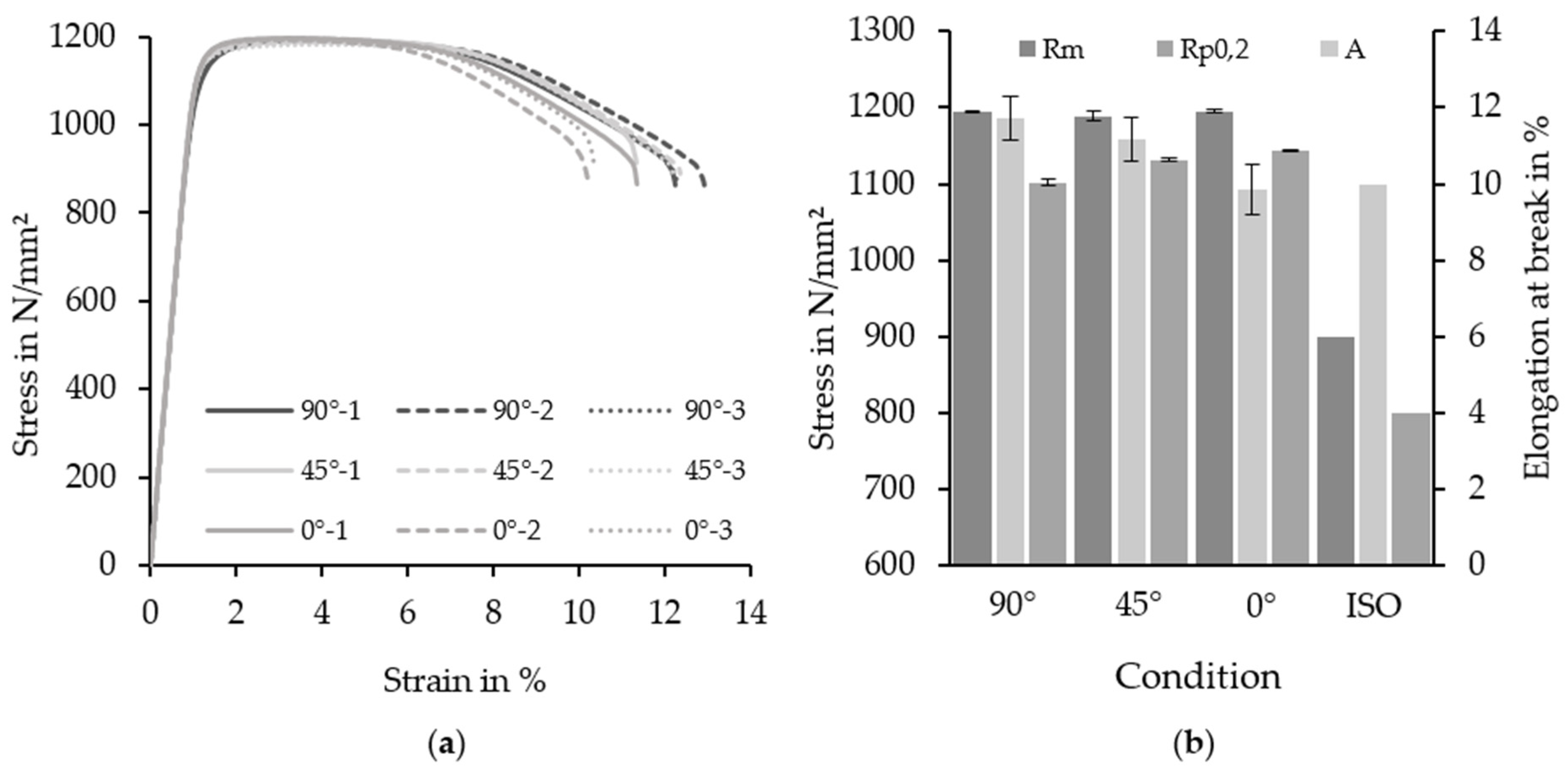
3.2. Monotonic Tensile Testing

All specimens examined using the monotonic tensile test failed in the extensometer range and could therefore be considered for analysis. Figure 5a shows the results as stress–strain curves for the build orientations 90°, 45°, and 0°. The corresponding mean values including the standard deviation concerning ultimate tensile strength (UTS) Rm, yield strength (YS) Rp0,2, and elongation at break (A) are illustrated in comparison with ISO 5832-11 [40] (Figure 5b). From the results it can be seen that the as-built Ti-6Al-7Nb tended to reach high ultimate tensile strengths (>900 MPa) and yield strengths (>800 MPa) irrespective of the build orientation. The achieved values were significantly higher than those of conventional Ti-6Al-7Nb (Rm = 900−1050 MPa and Rp0,2 = 880−950 MPa) [63,64]. The indicated difference in the mechanical behavior was explained by the distinctive microstructure obtained in the respective manufacturing process [65]. In wrought Ti-6Al7Nb, the size and morphology of coarse α grains shaped in the form of an equiaxed-like microstructure controlled the mechanical properties, whereas on the contrary, as-built Ti-6Al-7Nb properties were determined by sizing of fine martensitic α’ laths [66,67,68]. Since the onset of plastic deformation was delayed by the presence of a small-grained microstructure, the as-built state reached significantly higher yield stresses and strengths but lower plastic deformation [69,70]. Beyond that, the increased mechanical properties of PBF-LB/M processed Ti-6Al-7Nb were strongly justified by high residual stresses and martensitic transformation due to high cooling rates as well as grain refinement as a strength mechanism [71,72].
The mechanical properties regarding tensile strength (>900 MPa) and yield strength (>800 MPa) defined as per ISO 5832-11 [40] were exceeded by the as-built Ti-6Al-7Nb irrespective of the building orientation. According to the ultimate tensile and yield strength, the build orientation had no significant influence, and the values showed no substantial difference for the considered build orientations of 90° (Rm = 1194 ± 2 MPa, Rp0,2 = 1102 ± 5 MPa), 45° (Rm = 1132 ± 2 MPa, Rp0,2 = 1102 ± 2 MPa), and 0° (Rm = 1195 ± 2 MPa, Rp0,2 = 1143 ± 1 MPa). In addition, Table 3 shows the build orientation had no significant influence on the Young’s modulus. The change for different building orientations of 90° (E = 113 ± 1 GPa), 45° (E = 113 ± 1 GPa), and 0° (112 ± 2 GPa) as described in the literature could not be demonstrated in this work [73]. This may be explained by the less pronounced α’ texture, which did not change significantly with different build orientations (Figure 4e–g). The orientation of prior β grains had no influence on the Young’s modulus, ultimate tensile strength, and yield strength.
A reduction in elongation at break could be determined as the build-up angle increased. While the 90° (A = 11.7 ± 0.6%) and 45° (A = 11.2 ± 0.6%) samples achieved the elongation at break required by ISO 3285-11 [40] (>10%), 0° (A = 9.8 ± 0.7%) samples partially met the requirements. It is well known from the literature that the presence of internal, PBF-LB/M typical, defects such as pores leads to a decreased deformation behavior [74,75,76,77,78]. Therefore, fractography analysis of the 90°-, 45°-, and 0°-tensile specimens were taken and analyzed in the following.

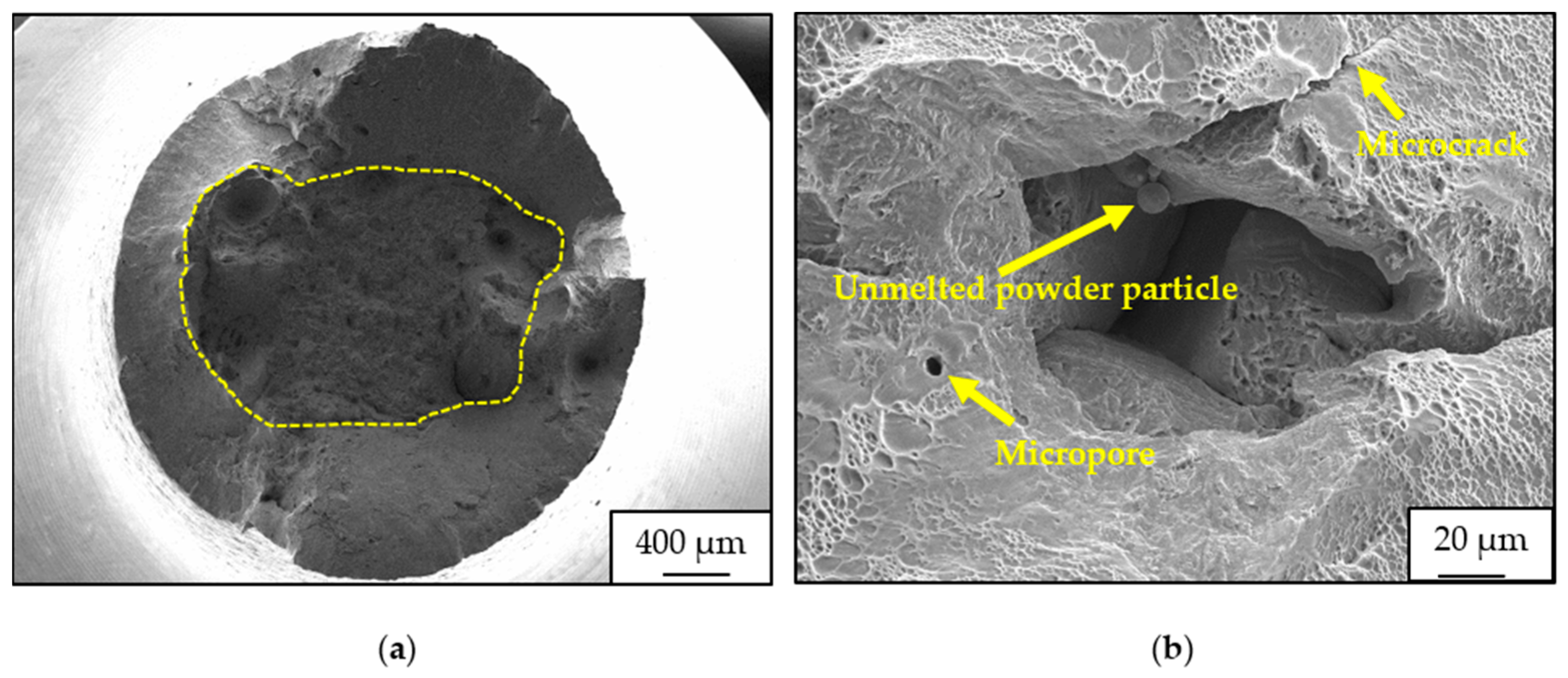
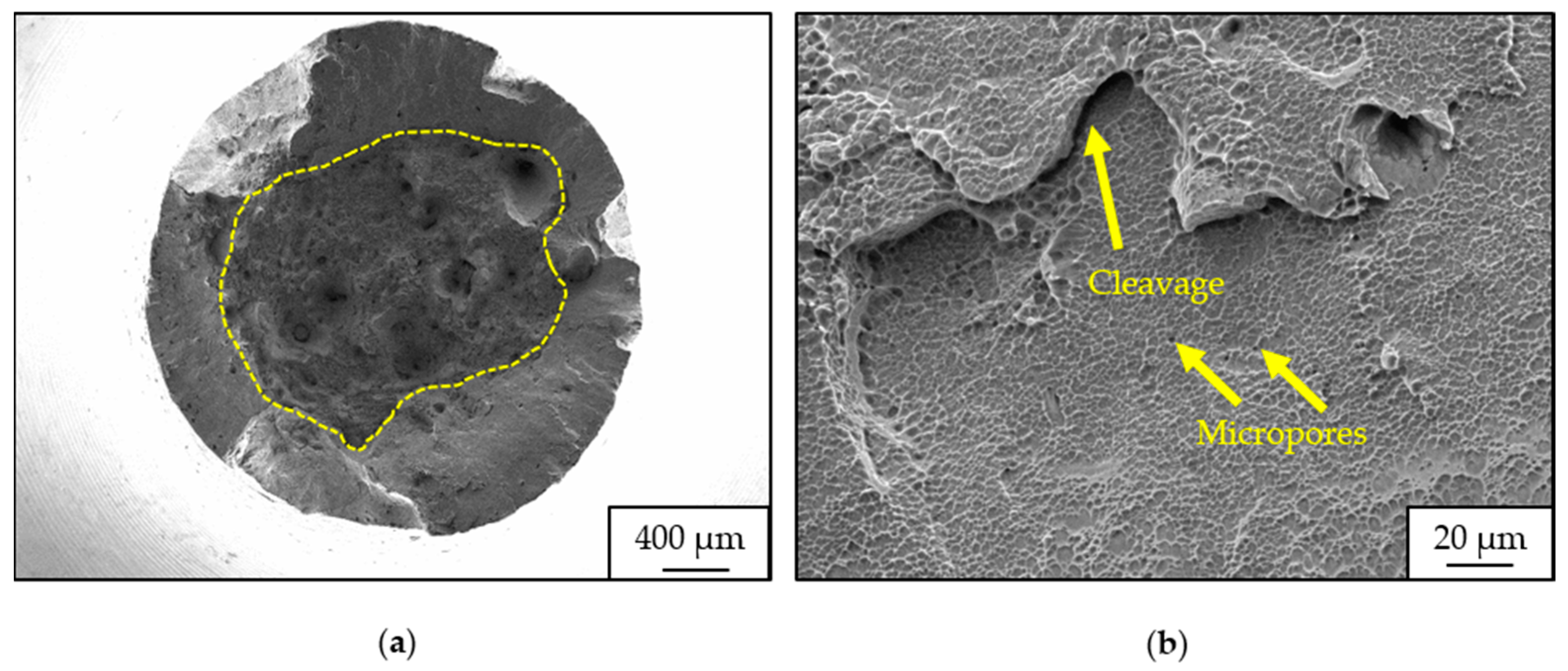
Fractography of Tensile Specimens

An overview of selected fracture surfaces of as-built Ti-6Al-7Nb with different build orientations is shown in Figure 6a, Figure 7a and Figure 8a. On the fracture surface of all Ti-6Al-7Nb specimens, a cup-cone-shaped failure surface and the shear lip representing the ductile fracture behavior were observed. The latter was predominantly detected on the fracture surfaces in the form of transangular dimples. Fracture surface defects of different sizes and types were mainly detected in the inner part of the fracture surface (circled with yellow dashed lines). Figure 6b, Figure 7b and Figure 8b highlight characteristics of fracture surfaces at higher magnifications to better define the defects. The fracture surface of 0° samples was characterized by the presence of micro-cracks originating from pore-like features (Figure 6b). Presumably, these features were irregular lack-of-fusion pores as unmolten powder particles could be detected internally. In a mechanical sense, internal defects such as irregular pores posed a challenge as they accumulated the flow of force under tensile load and tended to an area of stress concentration [79]. Consequently, the initialization of a crack was more apparent in the stress-accumulated areas and may significantly reduce the service life of components [80,81]. In enhancement, gas pores and quasi-cleavage facets with a high accumulation of dimples at the grain boundaries of 0° samples were discovered. The fracture surfaces of the 45° and 90° samples showed identical fracture characteristics compared with those of the 0° samples, except for irregular lack-of-fusion pores. However, the fracture surfaces of the 0° samples revealed more and larger defects than those of the 45° and 90° fracture surfaces. This effect may be explained by the directional heat dissipation during the PBF-LB/M process. As the PBF-LB/M process was a directional solidification process, the heat dissipation occurred aligned with the build orientation. In the 90° build orientation, the heat was dissipated directly via the solidified structure under the powder layer, while in samples with an overhang angle, the heat was dissipated via the less thermally conductive powder [82].
With decreasing thermal conductivity, the size of the melt pool increased due to a local temperature increase by heat accumulation. The resulting increase in the penetration depth of the weld pool presumably led to the formation of defects [83,84]. Moreover, micropores and a more distinct cone-shaped structure, originating from larger pores, could be detected in the 45° and 90° orientations accompanied by finer and deeper dimples indicating good plastic deformation and good ductility.

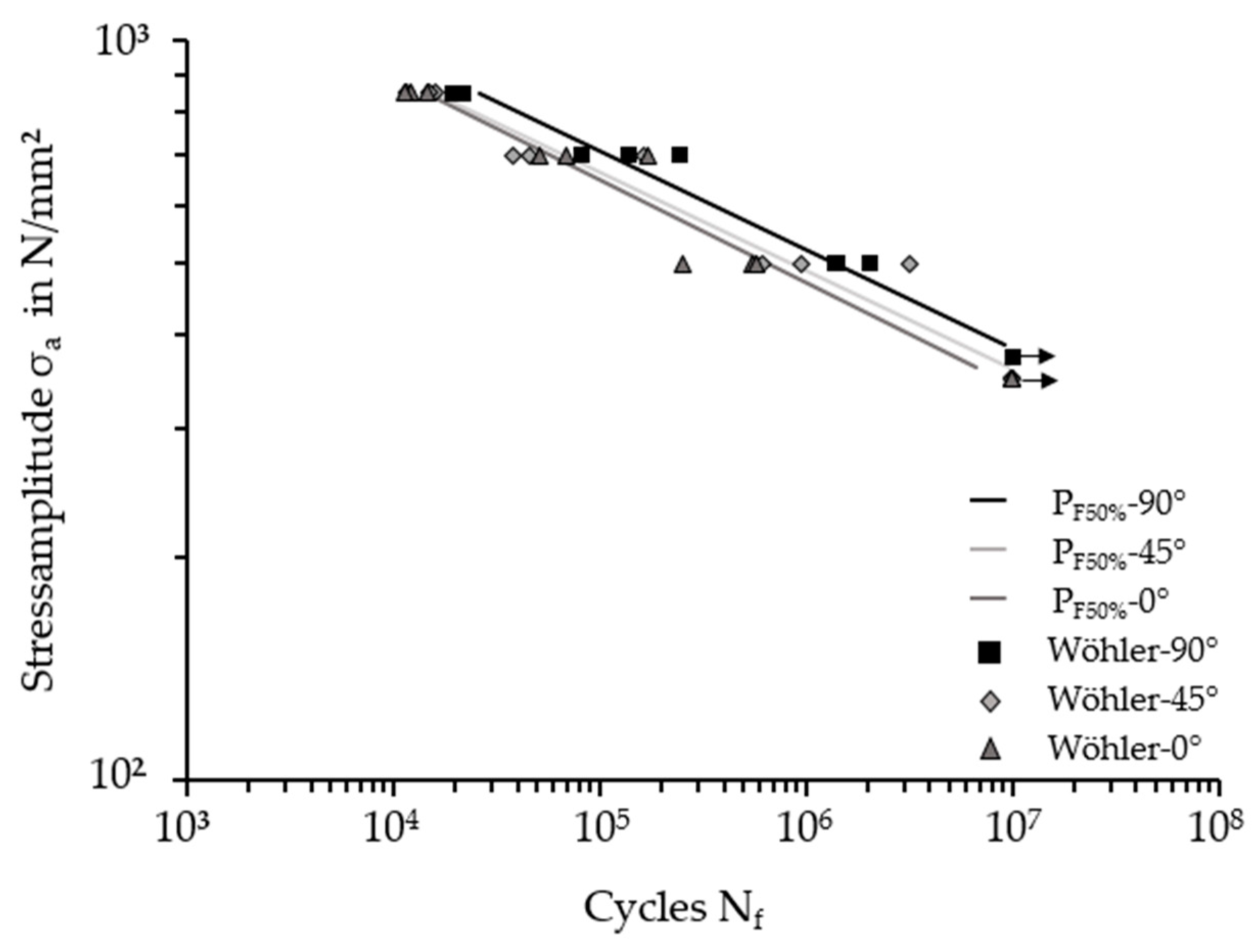
3.3. High Cycle Fatigue Testing

High cycle fatigue tests were performed on different stress levels to determine the effect of the build orientation on the fatigue behavior. For each build orientation, stress levels at 850 MPa, 700 MPa, and 500 MPa were analyzed to enclose the area of fatigue life between finite-life long and long-life strength ranges. The average long-life fatigue strength was obtained using SC tests for every build orientation. All results are summarized in a double-logarithmic stress amplitude–cycle diagram (Figure 9). Samples achieving 107 cycles were designated as runouts (black arrows). The straight lines show an improvement in the average long-life fatigue strength of as-built Ti-6Al-7Nb in the 90° build orientation.
The average long-life fatigue strengths of 0° and 45° as-built Ti-6Al-7Nb were 361.72 MPa and 362.29 MPa, respectively, while 90° as-built Ti-6Al-7Nb attained the highest value of 387.54 MPa. The increased fatigue behavior of 90° as-built Ti-6Al-7Nb could be attributed to the effects of defects on the fatigue performance as reported in the literature [37,47,75]. Defects serve as nucleation points for fatigue cracks due to the local stress concentration [85]. This conclusion needs to be correlated with fracture surface analysis.

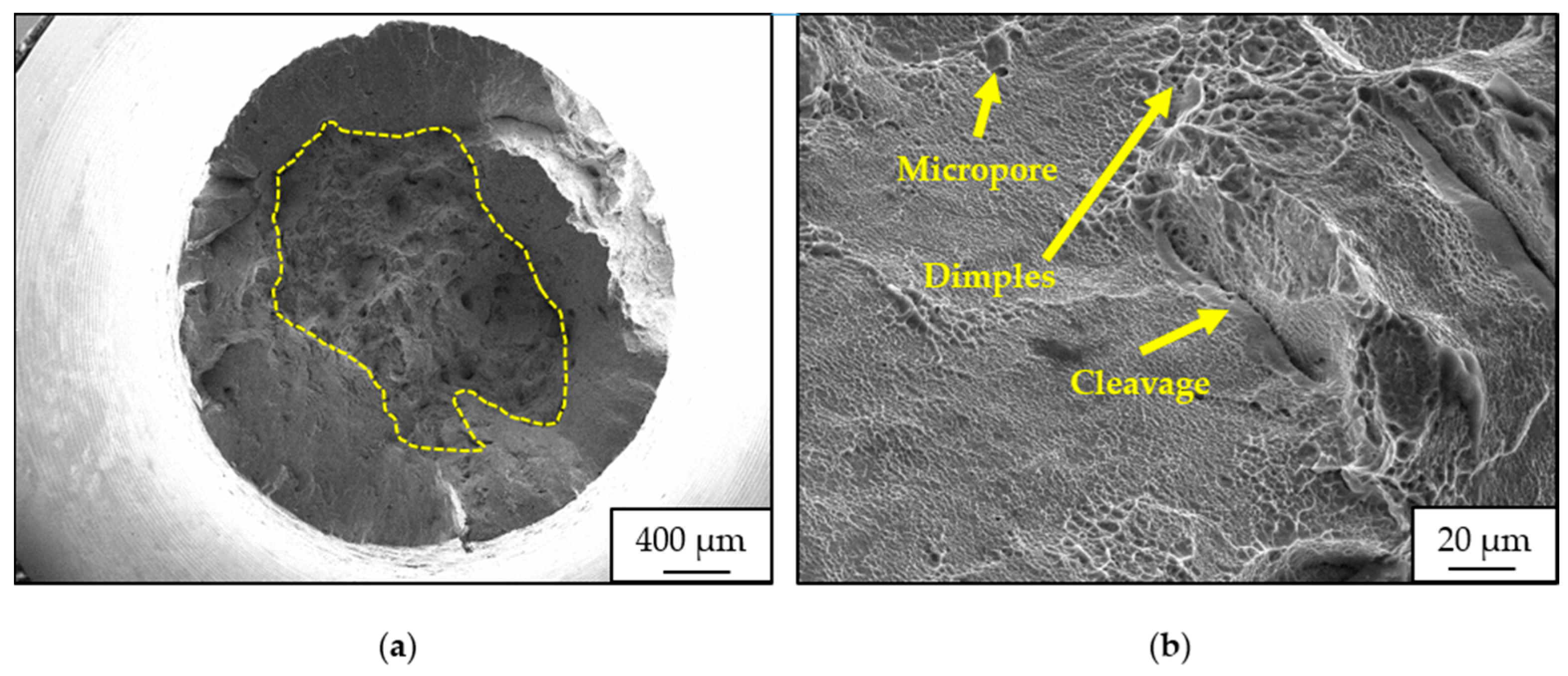
Fractography of HCF Specimens

Figure 10a–c display fracture surfaces of as-built Ti-6Al-7Nb samples with different building orientations at a stress amplitude of 400 MPa. Crack nucleation sites can be identified on fracture surfaces in Figure 10d–f. With increasing crack propagation, the effective cross-sectional area decreases and leads to the final residual fracture surface at constant stress amplitudes. The crack propagation area generally reveals PBF-LB/M typical defects like cracks and different types of pores independent of the build orientation (Figure 10g–i) [85]. Examination of crack nucleation reveals local internal defects such as pores to be potential areas for cracks under fatigue loading. Figure 10d–f show crack nucleation zones of the 90°, 45°, and 0° specimen areas with unmolten powder particles near the boundary of the specimen, which are presumably related to the lack of fusion. Typically, lack-of-fusion defects are oriented perpendicular to the build orientation and, due to their irregular and near-elliptical shape, are harmful because of local stress concentrations [86,87,88].
The morphological shapes of these defects seemed to differ with changing build orientation, which could be explained by the projection on the surface perpendicular to the direction of the force. In the 0° specimens, lack-of-fusion defects occurred with deeper and sharper shapes compared with those of the spherical 45° and 90° samples, which were localized close to the specimen surface. Surfaces near defects were highly destructive for the fatigue performance as a crack does not necessarily have to be induced by intrusion and extrusion formation [89,90]. In contrast, the crack nucleation of the 90° samples was approximately 100 µm away from the sample surface. However, apart from micropores and cracks, the 90° fracture surfaces did not exhibit any near-surface lack of fusion defects. This resulted in an improved fatigue performance.

4. Conclusions

This study addressed the effects of different build orientations on the monotonic tensile and fatigue performances of PBF-LB/M processed Ti-6Al-7Nb. The results were illustrated in the stress–strain and the S–N curves and correlated with the fracture surface analysis. The main findings can be summarized as follows:
  • The microstructure of as-built Ti-6Al-7Nb was characterized by columnar β grains growing parallel to the build direction. Inside prior β grains, fine acicular α′ martensite was composed due to the high cooling rates in the PBF-LB/M process. The characteristics of the microstructure were independent of the build orientation.
  • Fracture analysis of tensile specimens revealed a mixed mode of ductile and brittle fracture behavior.
  • The build orientation had a significant influence on the ductility, whereas the tensile strength, yield strength, and Young’s modulus were not affected. The 0° specimens showed the poorest elongation at break, while the 90°- and 45°-orientated specimens met all requirements of the standard ISO 5832-11.
  • Fatigue tests revealed that the build orientation had a significant influence on fatigue performance. The 0° specimens showed the best performance with an average long-life fatigue strength of 387.54 MPa.
  • The overall poorer performance of the 0° specimens in the tensile and fatigue tests regarding elongation at break and average long-life fatigue strength could be attributed to a higher number of defects, as well as to near-surface lack-of-fusion defects.

Author Contributions

Conceptualization, D.M. and K.-P.H.; methodology, D.M. and K.-P.H.; formal analysis, D.M.; investigation, D.M. and N.E.; resources, D.M., K.-P.H. and M.S.; data curation, D.M. and N.E.; writing—original draft preparation, D.M.; writing—review and editing, D.M. and K.-P.H.; visualization, D.M.; supervision, D.M., K.-P.H. and M.S.; project administration, K.-P.H. and M.S.; funding acquisition, M.S. All authors have read and agreed to the published version of the manuscript.

Funding

This research received no external funding.

Data Availability Statement

The data presented in this study are available on request from the corresponding author.

Acknowledgments

The authors are grateful for the support of the Chair of Materials Science (LWK) staff members and are especially thankful to Kay-Peter Hoyer and Mirko Schaper for their support and supervision. Sudipta Pramanik is acknowledged for performing β grain reconstruction.

Conflicts of Interest

The authors declare no conflicts of interest.

References

  1. Schmidt, M.; Merklein, M.; Bourell, D.; Dimitrov, D.; Hausotte, T.; Wegener, K.; Overmeyer, L.; Vollertsen, F.; Levy, G.N. Laser based additive manufacturing in industry and academia. CIRP Ann. 2017, 66, 561–583. [Google Scholar] [CrossRef]
  2. Blakey-Milner, B.; Gradl, P.; Snedden, G.; Brooks, M.; Pitot, J.; Lopez, E.; Leary, M.; Berto, F.; Du Plessis, A. Metal additive manufacturing in aerospace: A review. Mater. Des. 2021, 209, 110008. [Google Scholar] [CrossRef]
  3. Böckin, D.; Tillman, A.-M. Environmental assessment of additive manufacturing in the automotive industry. J. Clean. Prod. 2019, 226, 977–987. [Google Scholar] [CrossRef]
  4. Kumar, R.; Kumar, M.; Chohan, J.S. The role of additive manufacturing for biomedical applications: A critical review. J. Manuf. Process. 2021, 64, 828–850. [Google Scholar] [CrossRef]
  5. New Manufacturing Milestone: 30,000 Additive Fuel Nozzles|GE Additive. Available online: https://www.ge.com/additive/stories/new-manufacturing-milestone-30000-additive-fuel-nozzles (accessed on 26 June 2023).
  6. Nouri, A.; Rohani Shirvan, A.; Li, Y.; Wen, C. Additive manufacturing of metallic and polymeric load-bearing biomaterials using laser powder bed fusion: A review. J. Mater. Sci. Technol. 2021, 94, 196–215. [Google Scholar] [CrossRef]
  7. Yap, C.Y.; Chua, C.K.; Dong, Z.L.; Liu, Z.H.; Zhang, D.Q.; Loh, L.E.; Sing, S.L. Review of selective laser melting: Materials and applications. Appl. Phys. Rev. 2015, 2, 041101. [Google Scholar] [CrossRef]
  8. Zhang, Y.; Yang, S.; Zhao, Y.F. Manufacturability analysis of metal laser-based powder bed fusion additive manufacturing—A survey. Int. J. Adv. Manuf. Technol. 2020, 110, 57–78. [Google Scholar] [CrossRef]
  9. Sing, S.L.; Yeong, W.Y. Laser powder bed fusion for metal additive manufacturing: Perspectives on recent developments. Virtual Phys. Prototyp. 2020, 15, 359–370. [Google Scholar] [CrossRef]
  10. Colombo-Pulgarín, J.C.; Biffi, C.A.; Vedani, M.; Celentano, D.; Sánchez-Egea, A.; Boccardo, A.D.; Ponthot, J.-P. Beta Titanium Alloys Processed by Laser Powder Bed Fusion: A Review. J. Mater. Eng. Perform. 2021, 30, 6365–6388. [Google Scholar] [CrossRef]
  11. Santecchia, E.; Spigarelli, S.; Cabibbo, M. Material Reuse in Laser Powder Bed Fusion: Side Effects of the Laser—Metal Powder Interaction. Metals 2020, 10, 341. [Google Scholar] [CrossRef]
  12. Oliveira, J.P.; LaLonde, A.D.; Ma, J. Processing parameters in laser powder bed fusion metal additive manufacturing. Mater. Des. 2020, 193, 108762. [Google Scholar] [CrossRef]
  13. Wu, J.; Wang, X.Q.; Wang, W.; Attallah, M.M.; Loretto, M.H. Microstructure and strength of selectively laser melted AlSi10Mg. Acta Mater. 2016, 117, 311–320. [Google Scholar] [CrossRef]
  14. Davoodi, E.; Montazerian, H.; Mirhakimi, A.S.; Zhianmanesh, M.; Ibhadode, O.; Shahabad, S.I.; Esmaeilizadeh, R.; Sarikhani, E.; Toorandaz, S.; Sarabi, S.A.; et al. Additively manufactured metallic biomaterials. Bioact. Mater. 2022, 15, 214–249. [Google Scholar] [CrossRef] [PubMed]
  15. Gatto, M.L.; Furlani, M.; Giuliani, A.; Bloise, N.; Fassina, L.; Visai, L.; Mengucci, P. Biomechanical performances of PCL/HA micro- and macro-porous lattice scaffolds fabricated via laser powder bed fusion for bone tissue engineering. Mater. Sci. Eng. C Mater. Biol. Appl. 2021, 128, 112300. [Google Scholar] [CrossRef]
  16. Attar, H.; Prashanth, K.G.; Chaubey, A.K.; Calin, M.; Zhang, L.C.; Scudino, S.; Eckert, J. Comparison of wear properties of commercially pure titanium prepared by selective laser melting and casting processes. Mater. Lett. 2015, 142, 38–41. [Google Scholar] [CrossRef]
  17. Bartolomeu, F.; Sampaio, M.; Carvalho, O.; Pinto, E.; Alves, N.; Gomes, J.R.; Silva, F.S.; Miranda, G. Tribological behavior of Ti6Al4V cellular structures produced by Selective Laser Melting. J. Mech. Behav. Biomed. Mater. 2017, 69, 128–134. [Google Scholar] [CrossRef] [PubMed]
  18. Campanelli, L.C. A review on the recent advances concerning the fatigue performance of titanium alloys for orthopedic applications. J. Mater. Res. 2020, 36, 151–165. [Google Scholar] [CrossRef]
  19. Dai, N.; Zhang, L.-C.; Zhang, J.; Zhang, X.; Ni, Q.; Chen, Y.; Wu, M.; Yang, C. Distinction in corrosion resistance of selective laser melted Ti-6Al-4V alloy on different planes. Corros. Sci. 2016, 111, 703–710. [Google Scholar] [CrossRef]
  20. Hao, Y.-L.; Li, S.-J.; Yang, R. Biomedical titanium alloys and their additive manufacturing. Rare Met. 2016, 35, 661–671. [Google Scholar] [CrossRef]
  21. Costa, B.C.; Tokuhara, C.K.; Rocha, L.A.; Oliveira, R.C.; Lisboa-Filho, P.N.; Costa Pessoa, J. Vanadium ionic species from degradation of Ti-6Al-4V metallic implants: In vitro cytotoxicity and speciation evaluation. Mater. Sci. Eng. C Mater. Biol. Appl. 2019, 96, 730–739. [Google Scholar] [CrossRef]
  22. Haase, F.; Siemers, C.; Klinge, L.; Lu, C.; Lang, P.; Lederer, S.; König, T.; Rösler, J. Aluminum- and Vanadium-free Titanium Alloys for Medical Applications. MATEC Web Conf. 2020, 321, 5008. [Google Scholar] [CrossRef]
  23. Kim, K.T.; Eo, M.Y.; Nguyen, T.T.H.; Kim, S.M. General review of titanium toxicity. Int. J. Implant Dent. 2019, 5, 10. [Google Scholar] [CrossRef] [PubMed]
  24. Rojas-Lemus, M.; López-Valdez, N.; Bizarro-Nevares, P.; González-Villalva, A.; Ustarroz-Cano, M.; Zepeda-Rodríguez, A.; Pasos-Nájera, F.; García-Peláez, I.; Rivera-Fernández, N.; Fortoul, T.I. Toxic Effects of Inhaled Vanadium Attached to Particulate Matter: A Literature Review. Int. J. Environ. Res. Public Health 2021, 18, 8457. [Google Scholar] [CrossRef]
  25. Chen, Q.; Thouas, G.A. Metallic implant biomaterials. Mater. Sci. Eng. R Rep. 2015, 87, 1–57. [Google Scholar] [CrossRef]
  26. Li, B.Q.; Lu, X. A Biomedical Ti-35Nb-5Ta-7Zr Alloy Fabricated by Powder Metallurgy. J. Mater. Eng. Perform. 2019, 28, 5616–5624. [Google Scholar] [CrossRef]
  27. Kobayashi, E.; Wang, T.J.; Doi, H.; Yoneyama, T.; Hamanaka, H. Mechanical properties and corrosion resistance of Ti-6Al-7Nb alloy dental castings. J. Mater. Sci. Mater. Med. 1998, 9, 567–574. [Google Scholar] [CrossRef] [PubMed]
  28. Kobayashi, E.; Mochizuki, H.; Doi, H.; Yoneyama, T.; Hanawa, T. Fatigue Life Prediction of Biomedical Titanium Alloys under Tensile/Torsional Stress. Mater. Trans. 2006, 47, 1826–1831. [Google Scholar] [CrossRef]
  29. Iijima, D.; Yoneyama, T.; Doi, H.; Hamanaka, H.; Kurosaki, N. Wear properties of Ti and Ti-6Al-7Nb castings for dental prostheses. Biomaterials 2003, 24, 1519–1524. [Google Scholar] [CrossRef]
  30. Leyens, C.; Peters, M. Titanium and Titanium Alloys: Fundamentals and Applications; Wiley-VCH: Weinheim, Germany, 2003; ISBN 3527305343. [Google Scholar]
  31. Shaikh, A.; Kumar, S.; Dawari, A.; Kirwai, S.; Patil, A.; Singh, R. Effect of Temperature and Cooling Rates on the α+β Morphology of Ti-6Al-4V Alloy. Procedia Struct. Integr. 2019, 14, 782–789. [Google Scholar] [CrossRef]
  32. Liu, S.; Shin, Y.C. Additive manufacturing of Ti6Al4V alloy: A review. Mater. Des. 2019, 164, 107552. [Google Scholar] [CrossRef]
  33. Kok, Y.; Tan, X.P.; Wang, P.; Nai, M.; Loh, N.H.; Liu, E.; Tor, S.B. Anisotropy and heterogeneity of microstructure and mechanical properties in metal additive manufacturing: A critical review. Mater. Des. 2018, 139, 565–586. [Google Scholar] [CrossRef]
  34. Mahmud, A.; Huynh, T.; Le, Z.; Hyer, H.; Mehta, A.; Imholte, D.D.; Woolstenhulme, N.E.; Wachs, D.M.; Sohn, Y. Mechanical Behavior Assessment of Ti-6Al-4V ELI Alloy Produced by Laser Powder Bed Fusion. Metals 2021, 11, 1671. [Google Scholar] [CrossRef]
  35. Rans, C.; Michielssen, J.; Walker, M.; Wang, W.; Hoen-Velterop, L. Beyond the orthogonal: On the influence of build orientation on fatigue crack growth in SLM Ti-6Al-4V. Int. J. Fatigue 2018, 116, 344–354. [Google Scholar] [CrossRef]
  36. Simonelli, M.; Tse, Y.Y.; Tuck, C. Effect of the build orientation on the mechanical properties and fracture modes of SLM Ti–6Al–4V. Mater. Sci. Eng. A 2014, 616, 1–11. [Google Scholar] [CrossRef]
  37. Xu, Z.W.; Liu, A.; Wang, X.S. The influence of building direction on the fatigue crack propagation behavior of Ti6Al4V alloy produced by selective laser melting. Mater. Sci. Eng. A 2019, 767, 138409. [Google Scholar] [CrossRef]
  38. Dareh Baghi, A.; Nafisi, S.; Hashemi, R.; Ebendorff-Heidepriem, H.; Ghomashchi, R. Experimental realisation of build orientation effects on the mechanical properties of truly as-built Ti-6Al-4V SLM parts. J. Manuf. Process. 2021, 64, 140–152. [Google Scholar] [CrossRef]
  39. Jamshidi, P.; Aristizabal, M.; Kong, W.; Villapun, V.; Cox, S.C.; Grover, L.M.; Attallah, M.M. Selective Laser Melting of Ti-6Al-4V: The Impact of Post-processing on the Tensile, Fatigue and Biological Properties for Medical Implant Applications. Materials 2020, 13, 2813. [Google Scholar] [CrossRef] [PubMed]
  40. DIN ISO 5832-11:2015-12; Chirurgische Implantate—Metallische Werkstoffe—Teil_11: Titan Aluminium-6 Niob-7 Knetlegierung (ISO_5832-11:2014). Beuth Verlag GmbH: Berlin, Germany, 2015.
  41. Chlebus, E.; Kuźnicka, B.; Kurzynowski, T.; Dybała, B. Microstructure and mechanical behaviour of Ti―6Al―7Nb alloy produced by selective laser melting. Mater. Charact. 2011, 62, 488–495. [Google Scholar] [CrossRef]
  42. Sercombe, T.; Jones, N.; Day, R.; Kop, A. Heat treatment of Ti-6Al-7Nb components produced by selective laser melting. Rapid Prototyp. J. 2008, 14, 300–304. [Google Scholar] [CrossRef]
  43. Hein, M.; Hoyer, K.-P.; Schaper, M. Additively processed TiAl6Nb7 alloy for biomedical applications. Mater. Werkst. 2021, 52, 703–716. [Google Scholar] [CrossRef]
  44. Hein, M.; Kokalj, D.; Lopes Dias, N.F.; Stangier, D.; Oltmanns, H.; Pramanik, S.; Kietzmann, M.; Hoyer, K.-P.; Meißner, J.; Tillmann, W.; et al. Low Cycle Fatigue Performance of Additively Processed and Heat-Treated Ti-6Al-7Nb Alloy for Biomedical Applications. Metals 2022, 12, 122. [Google Scholar] [CrossRef]
  45. Xu, C.; Sikan, F.; Atabay, S.E.; Muñiz-Lerma, J.A.; Sanchez-Mata, O.; Wang, X.; Brochu, M. Microstructure and mechanical behavior of as-built and heat-treated Ti–6Al–7Nb produced by laser powder bed fusion. Mater. Sci. Eng. A 2020, 793, 139978. [Google Scholar] [CrossRef]
  46. Hein, M. Influence of Physical Vapor Deposition on High-Cycle Fatigue Performance of Additively Manufactured Ti-6Al-7Nb Alloy. Crystals 2022, 12, 1190. [Google Scholar] [CrossRef]
  47. Singla, A.K.; Banerjee, M.; Sharma, A.; Singh, J.; Bansal, A.; Gupta, M.K.; Khanna, N.; Shahi, A.S.; Goyal, D.K. Selective laser melting of Ti6Al4V alloy: Process parameters, defects and post-treatments. J. Manuf. Process. 2021, 64, 161–187. [Google Scholar] [CrossRef]
  48. DIN ISO 6892-1; Metallische Werkstoffe—Zugversuch—Teil 1: Prüfverfahren bei Raumtemperatur (ISO 6892-1:2019). Beuth Verlag GmbH: Berlin, Germany, 2020.
  49. DIN 50100; Schwingfestigkeitsversuch—Durchführung und Auswertung von zyklischen Versuchen mit konstanter Lastamplitude für metallische Werkstoffproben und Bauteile. DIN Deutsches Institut für Normung e. V.: Berlin, Germany, 2016.
  50. Lu, S.L.; Zhang, Z.J.; Liu, R.; Qu, Z.; Wang, B.; Zhou, X.H.; Eckert, J.; Zhang, Z.F. Prior β grain evolution and phase transformation of selective laser melted Ti6Al4V alloy during heat treatment. J. Alloys Compd. 2022, 914, 165235. [Google Scholar] [CrossRef]
  51. Phutela, C.; Aboulkhair, N.T.; Tuck, C.J.; Ashcroft, I. The Effects of Feature Sizes in Selectively Laser Melted Ti-6Al-4V Parts on the Validity of Optimised Process Parameters. Materials 2019, 13, 117. [Google Scholar] [CrossRef]
  52. Banerjee, D.; Williams, J.C. Perspectives on Titanium Science and Technology. Acta Mater. 2013, 61, 844–879. [Google Scholar] [CrossRef]
  53. Thijs, L.; Verhaeghe, F.; Craeghs, T.; van Humbeeck, J.; Kruth, J.-P. A study of the microstructural evolution during selective laser melting of Ti–6Al–4V. Acta Mater. 2010, 58, 3303–3312. [Google Scholar] [CrossRef]
  54. Simonelli, M.; Tse, Y.Y.; Tuck, C. The formation of α + β microstructure in as-fabricated selective laser melting of Ti–6Al–4V. J. Mater. Res. 2014, 29, 2028–2035. [Google Scholar] [CrossRef]
  55. Ren, S.; Chen, Y.; Liu, T.; Qu, X. Effect of Build Orientation on Mechanical Properties and Microstructure of Ti-6Al-4V Manufactured by Selective Laser Melting. Metall. Mater. Trans. A 2019, 50, 4388–4409. [Google Scholar] [CrossRef]
  56. DebRoy, T.; Wei, H.L.; Zuback, J.S.; Mukherjee, T.; Elmer, J.W.; Milewski, J.O.; Beese, A.M.; Wilson-Heid, A.; De, A.; Zhang, W. Additive manufacturing of metallic components—Process, structure and properties. Prog. Mater. Sci. 2018, 92, 112–224. [Google Scholar] [CrossRef]
  57. Yang, J.; Yu, H.; Yin, J.; Gao, M.; Wang, Z.; Zeng, X. Formation and control of martensite in Ti-6Al-4V alloy produced by selective laser melting. Mater. Des. 2016, 108, 308–318. [Google Scholar] [CrossRef]
  58. Yan, X.; Yin, S.; Chen, C.; Huang, C.; Bolot, R.; Lupoi, R.; Kuang, M.; Ma, W.; Coddet, C.; Liao, H.; et al. Effect of heat treatment on the phase transformation and mechanical properties of Ti6Al4V fabricated by selective laser melting. J. Alloys Compd. 2018, 764, 1056–1071. [Google Scholar] [CrossRef]
  59. Lütjering, G.; Williams, J.C. Titanium, 2nd ed.; Springer: Berlin/Heidelberg, Germany, 2007; ISBN 9783540730361. [Google Scholar]
  60. Pramanik, S.; Milaege, D.; Hoyer, K.-P.; Schaper, M. Additively manufactured novel Ti6Al7Nb circular honeycomb cellular solid for energy absorbing applications. Mater. Sci. Eng. A 2022, 854, 143887. [Google Scholar] [CrossRef]
  61. Lütjering, G. Influence of processing on microstructure and mechanical properties of (α + β) titanium alloys. Mater. Sci. Eng. A 1998, 243, 32–45. [Google Scholar] [CrossRef]
  62. Qiu, C.; Adkins, N.J.; Attallah, M.M. Microstructure and tensile properties of selectively laser-melted and of HIPed laser-melted Ti–6Al–4V. Mater. Sci. Eng. A 2013, 578, 230–239. [Google Scholar] [CrossRef]
  63. Zhang, L.-C.; Chen, L.-Y. A Review on Biomedical Titanium Alloys: Recent Progress and Prospect. Adv. Eng. Mater. 2019, 21, 1801215. [Google Scholar] [CrossRef]
  64. Niinomi, M. Mechanical properties of biomedical titanium alloys. Mater. Sci. Eng. A 1998, 243, 231–236. [Google Scholar] [CrossRef]
  65. Bajt Leban, M.; Kosec, T.; Finšgar, M. The corrosion resistance of dental Ti6Al4V with differing microstructures in oral environments. J. Mater. Res. Technol. 2023, 27, 1982–1995. [Google Scholar] [CrossRef]
  66. Shunmugavel, M.; Polishetty, A.; Littlefair, G. Microstructure and Mechanical Properties of Wrought and Additive Manufactured Ti-6Al-4V Cylindrical Bars. Procedia Technol. 2015, 20, 231–236. [Google Scholar] [CrossRef]
  67. Jaber, H.; Kónya, J.; Kulcsár, K.; Kovács, T. Effects of Annealing and Solution Treatments on the Microstructure and Mechanical Properties of Ti6Al4V Manufactured by Selective Laser Melting. Materials 2022, 15, 1978. [Google Scholar] [CrossRef]
  68. Dehnavi, V.; Henderson, J.D.; Dharmendra, C.; Amirkhiz, B.S.; Shoesmith, D.W.; Noël, J.J.; Mohammadi, M. Corrosion Behaviour of Electron Beam Melted Ti6Al4V: Effects of Microstructural Variation. J. Electrochem. Soc. 2020, 167, 131505. [Google Scholar] [CrossRef]
  69. Moridi, A.; Demir, A.G.; Caprio, L.; Hart, A.J.; Previtali, B.; Colosimo, B.M. Deformation and failure mechanisms of Ti–6Al–4V as built by selective laser melting. Mater. Sci. Eng. A 2019, 768, 138456. [Google Scholar] [CrossRef]
  70. Voisin, T.; Calta, N.P.; Khairallah, S.A.; Forien, J.-B.; Balogh, L.; Cunningham, R.W.; Rollett, A.D.; Wang, Y.M. Defects-dictated tensile properties of selective laser melted Ti-6Al-4V. Mater. Des. 2018, 158, 113–126. [Google Scholar] [CrossRef]
  71. Attar, H.; Calin, M.; Zhang, L.C.; Scudino, S.; Eckert, J. Manufacture by selective laser melting and mechanical behavior of commercially pure titanium. Mater. Sci. Eng. A 2014, 593, 170–177. [Google Scholar] [CrossRef]
  72. Syed, A.K.; Ahmad, B.; Guo, H.; Machry, T.; Eatock, D.; Meyer, J.; Fitzpatrick, M.E.; Zhang, X. An experimental study of residual stress and direction-dependence of fatigue crack growth behaviour in as-built and stress-relieved selective-laser-melted Ti6Al4V. Mater. Sci. Eng. A 2019, 755, 246–257. [Google Scholar] [CrossRef]
  73. Sun, W.; Ma, Y.; Huang, W.; Zhang, W.; Qian, X. Effects of build direction on tensile and fatigue performance of selective laser melting Ti6Al4V titanium alloy. Int. J. Fatigue 2020, 130, 105260. [Google Scholar] [CrossRef]
  74. Leuders, S.; Lieneke, T.; Lammers, S.; Tröster, T.; Niendorf, T. On the fatigue properties of metals manufactured by selective laser melting—The role of ductility. J. Mater. Res. 2014, 29, 1911–1919. [Google Scholar] [CrossRef]
  75. Leuders, S.; Vollmer, M.; Brenne, F.; Tröster, T.; Niendorf, T. Fatigue Strength Prediction for Titanium Alloy TiAl6V4 Manufactured by Selective Laser Melting. Met. Mater. Trans. A 2015, 46, 3816–3823. [Google Scholar] [CrossRef]
  76. Li, P.; Warner, D.H.; Fatemi, A.; Phan, N. Critical assessment of the fatigue performance of additively manufactured Ti–6Al–4V and perspective for future research. Int. J. Fatigue 2016, 85, 130–143. [Google Scholar] [CrossRef]
  77. Meng, L.X.; Yang, H.J.; Ben, D.D.; Ji, H.B.; Lian, D.L.; Ren, D.C.; Li, Y.; Bai, T.S.; Cai, Y.S.; Chen, J.; et al. Effects of defects and microstructures on tensile properties of selective laser melted Ti6Al4V alloys fabricated in the optimal process zone. Mater. Sci. Eng. A 2022, 830, 142294. [Google Scholar] [CrossRef]
  78. Liu, F.; He, C.; Chen, Y.; Zhang, H.; Wang, Q.; Liu, Y. Effects of defects on tensile and fatigue behaviors of selective laser melted titanium alloy in very high cycle regime. Int. J. Fatigue 2020, 140, 105795. [Google Scholar] [CrossRef]
  79. Nudelis, N.; Mayr, P. A Novel Classification Method for Pores in Laser Powder Bed Fusion. Metals 2021, 11, 1912. [Google Scholar] [CrossRef]
  80. Hu, Y.N.; Wu, S.C.; Wu, Z.K.; Zhong, X.L.; Ahmed, S.; Karabal, S.; Xiao, X.H.; Zhang, H.O.; Withers, P.J. A new approach to correlate the defect population with the fatigue life of selective laser melted Ti-6Al-4V alloy. Int. J. Fatigue 2020, 136, 105584. [Google Scholar] [CrossRef]
  81. Bhandari, L.; Gaur, V. A study on defect-induced fatigue failures in SLM Ti6Al4V Alloy. Procedia Struct. Integr. 2022, 42, 529–536. [Google Scholar] [CrossRef]
  82. Luo, Y.; Wang, M.; Tu, J.; Jiang, Y.; Jiao, S. Reduction of residual stress in porous Ti6Al4V by in situ double scanning during laser additive manufacturing. Int. J. Miner. Met. Mater. 2021, 28, 1844–1853. [Google Scholar] [CrossRef]
  83. Vastola, G.; Pei, Q.X.; Zhang, Y.-W. Predictive model for porosity in powder-bed fusion additive manufacturing at high beam energy regime. Addit. Manuf. 2018, 22, 817–822. [Google Scholar] [CrossRef]
  84. Gong, H.; Rafi, K.; Gu, H.; Starr, T.; Stucker, B. Analysis of defect generation in Ti–6Al–4V parts made using powder bed fusion additive manufacturing processes. Addit. Manuf. 2014, 1–4, 87–98. [Google Scholar] [CrossRef]
  85. Afroz, L.; Inverarity, S.B.; Qian, M.; Easton, M.; Das, R. Analysing the effect of defects on stress concentration and fatigue life of L-PBF AlSi10Mg alloy using finite element modelling. Prog. Addit. Manuf. 2023, 1–9. [Google Scholar] [CrossRef]
  86. Zerbst, U.; Bruno, G.; Buffiere, J.-Y.; Wegener, T.; Niendorf, T.; Wu, T.; Zhang, X.; Kashaev, N.; Meneghetti, G.; Hrabe, N.; et al. Damage tolerant design of additively manufactured metallic components subjected to cyclic loading: State of the art and challenges. Prog. Mater. Sci. 2021, 121, 100786. [Google Scholar] [CrossRef]
  87. Afkhami, S.; Dabiri, M.; Alavi, S.H.; Björk, T.; Salminen, A. Fatigue characteristics of steels manufactured by selective laser melting. Int. J. Fatigue 2019, 122, 72–83. [Google Scholar] [CrossRef]
  88. Liang, X.; Hor, A.; Robert, C.; Salem, M.; Lin, F.; Morel, F. High cycle fatigue behavior of 316L steel fabricated by laser powder bed fusion: Effects of surface defect and loading mode. Int. J. Fatigue 2022, 160, 106843. [Google Scholar] [CrossRef]
  89. Polák, J.; Man, J. Mechanisms of extrusion and intrusion formation in fatigued crystalline materials. Mater. Sci. Eng. A 2014, 596, 15–24. [Google Scholar] [CrossRef]
  90. Siddique, S.; Imran, M.; Rauer, M.; Kaloudis, M.; Wycisk, E.; Emmelmann, C.; Walther, F. Computed tomography for characterization of fatigue performance of selective laser melted parts. Mater. Des. 2015, 83, 661–669. [Google Scholar] [CrossRef]
Figure 1. Gas-atomized Ti-6Al-7Nb powder characterization. (a) Particle size distribution. (b) SEM image of powder particles.
Crystals 14 00117 g001
Figure 2. Schematic illustration of PBF-LB/M. (a) Build job with cylindrical specimens in 90°, 45°, and 0° orientations (blue represents the support structure). (b) Sample design for monotonic tensile tests. (c) Sample design for HCF tests.
Crystals 14 00117 g002
Figure 3. Examination of relative density. (a) Light optical micrograph of cubic Ti-6Al-7Nb as-built sample with a relative density of 99.99%. (bd) µCT images taken across the respective measuring range of 90°, 45°, and 0° Ti-6Al-7Nb tensile specimens with a relative density above 99.98%.
Crystals 14 00117 g003
Figure 4. Microstructure analysis of as-built Ti-6Al-7Nb for different building orientations. Light micrographs: (a) 90°, (b) 45°, and (c) 0°. EBSD orientation maps: (d) 90°, (e) 45°, and (f) 0°. EBSD orientation maps of reconstructed β grains: (g) 90°, (h) 45°, and (i) 0°.
Crystals 14 00117 g004
Figure 5. Results of monotonic tensile tests for as-built 90°, 45°, and 0° Ti-6Al-7Nb. (a) Stress–strain curves. (b) Mechanical properties in consideration of the ultimate tensile strength (Rm) and yield strength (Rp0,2), as well as the elongation at break (A) in comparison with values defined as per ISO 5832-11.
Crystals 14 00117 g005
Figure 6. (a) SEM images of a tensile fracture surface of the 0° as-built Ti-6Al-7Nb specimen. (b) Higher magnification of defects on the corresponding fracture surface.
Crystals 14 00117 g006
Figure 7. (a) SEM images of a tensile fracture surface of the 45° as-built Ti-6Al-7Nb specimen. (b) Higher magnification of defects on the corresponding fracture surface.
Crystals 14 00117 g007
Figure 8. (a) SEM images of a tensile fracture surface of the 90° as-built Ti-6Al-7Nb specimen. (b) Higher magnification of defects on the corresponding fracture surface.
Crystals 14 00117 g008
Figure 9. Results of experimental Wöhler tests (filled symbols) of different build orientations at different stress levels with the corresponding failure probability curves PF50%.
Crystals 14 00117 g009
Figure 10. Fracture surfaces of as-built Ti-6Al-7Nb fatigue specimens after fatigue testing: (a) 90° as-built Ti-6Al-7Nb (stress amplitude 400 MPa), (b) 45° as-built Ti-6Al-7Nb (stress amplitude 400 MPa), and (c) 0° as-built Ti-6Al-7Nb (stress amplitude 400 MPa). (df) Magnifications of corresponding regions (a) Blue sqare, (b) Brown square–(c) Violett square. (gi) Magnifications of defects in (a) Orange Square, (b) Dark green, (c) Light green.
Crystals 14 00117 g010
Table 1. Chemical composition of investigated materials regarding ISO 5832-11 standard.
ConditionTi in wt.%Al in wt.%Nb in wt.%Fe in wt.%O in wt.%
Ti-6Al-7Nb
(ISO 5832-11)
Balance5.5–6.56.5–7.5<0.25<0.2
Ti-6Al-7Nb powder
(supplier)
Balance6.026.530.190.12
Ti-6Al-7Nb cuboid
(OES)
Balance5.747.050.120.08
Table 2. Ti-6Al-7Nb process parameters used for fabrication of fully dense samples.
Laser Power
in W
Laser Scanning Speed
in m‧s−1
Hatch Distance
in mm
Layer Thickness
in mm
Ti-6Al-7Nb3051.650.100.05
Table 3. Results of monotonic tensile test of PBF-LB/M processed as-built Ti-6Al-7Nb regarding the build orientation including mean values and associated standard deviations of ultimate tensile strength (Rm), yield strength (Rp0,2), and Young’s modulus (E), as well as elongation at break (A) for all samples tested in comparison with the ISO 5832-11 [40] standard.
Condition/SpecimenRm in MPaRp0,2 in MPaE in GPaA in %
90°-11192109711311.5
90°-21195110311312.2
90°-31195110611211.5
Mean value 90°1194110211311.7
Standard deviation 90°±2±5±1±0.6
45°-11195113211210.5
45°-21183113311311.6
45°-31186113011411.4
Mean value 45°1189113211311.2
Standard deviation 45°±6±2±1±0.6
0°-11197114311310.6
0°-2119311431119.4
0°-3119611441129.5
Mean value 0°119511431129.8
Standard deviation 0°±2±1±1±0.7
ISO 5832-11 [40]900800-10
Disclaimer/Publisher’s Note: The statements, opinions and data contained in all publications are solely those of the individual author(s) and contributor(s) and not of MDPI and/or the editor(s). MDPI and/or the editor(s) disclaim responsibility for any injury to people or property resulting from any ideas, methods, instructions or products referred to in the content.

