Article

Crystalline Microstructure, Microsegregations, and Mechanical Properties of Inconel 718 Alloy Samples Processed in Electromagnetic Levitation Facility

1
Otto Schott Institute of Materials Research, Friedrich Schiller University Jena, 07743 Jena, Germany
2
Institut für Materialphysik im Weltraum, Deutsches Zentrum für Luft- und Raumfahrt (DLR), 51147 Köln, Germany
*
Author to whom correspondence should be addressed.
Crystals 2024, 14(3), 244; https://doi.org/10.3390/cryst14030244
Submission received: 20 December 2023 / Revised: 18 January 2024 / Accepted: 18 February 2024 / Published: 29 February 2024
(This article belongs to the Special Issue Phase Transition in External Fields (2nd Edition))

Abstract

:
The solidification of Inconel 718 alloy (IN718) from undercooled liquid is studied. The solidification kinetics is evaluated in melted and undercooled droplets processed using the electromagnetic levitation (EML) technique by the temperature–time profiles and solid/liquid (S/L) interface movement during recalescence. The kinetics is monitored in real time by special pyrometrical measurements and high-speed digital camera. It is shown that the growth velocity of γ -phase (the primary phase in IN718), the final crystalline microstructure (dendritic and grained), and the mechanical properties (microhardness) are strongly dependent on the initial undercooling Δ T at which the samples started to solidify with the originating γ -phase. Particularly, with the increase in undercooling, the secondary dendrite arm spacing decreases from 28 μm to 5 μm. At small and intermediate ranges of undercooling, the solidified droplets have a dendritic crystalline microstructure. At higher undercooling values reached in the experiment, Δ T > 160 K (namely, for samples solidified with Δ T = 170 K and Δ T = 263 K), fine crystalline grains are observed instead of the dendritic structure of solidified drops. Such change in the crystalline morphology is qualitatively consistent with the behavior of crystal growth kinetics which exhibits the change from the power law to linear law at Δ T 160 K in the velocity–undercooling relationship (measured by the advancement of the recalescence front in solidifying droplets). Study of the local mechanical properties shows that the microhardness increases with the increase in the γ -phase within interdendritic spacing. The obtained data are the basis for testing the theoretical and computational of multicomponent alloy samples.

1. Introduction

Ni-based superalloys are materials that exhibit excellent mechanical strength, high temperature resistance, and good corrosion resistance [1,2]. The IN718 alloy, well known for its exceptional mechanical properties, is a nickel-rich alloy that undergoes a sophisticated precipitation hardening process [3,4]. The alloy is characterized by the formation of ordered body-centered tetragonal precipitates, specifically in the form of γ -phase, which are finely dispersed within the γ -matrix. This complex microstructural arrangement plays a key role in enhancing the overall strength and performance of the alloy. The ordered γ -precipitates, primarily composed of N i 3 N b , contribute significantly to the alloy’s strength by impeding dislocation movement and hindering the progress of plastic deformation. As the volume percentage of γ increases, a more refined and densely populated precipitate network forms, leading to a corresponding increase in strength [5,6,7].
Previous experimental studies [8] and computations [9,10] show that the microstructure, segregation of chemical elements, and alloy preparation technique have a substantial effect on the mechanical properties of the Inconel samples. The chemical segregation and crystalline microstructure were investigated experimentally and computationally in the positive temperature gradient [9,10] consistent with the welding and additive manufacturing processing for small thermal gradients and cooling rates. For example, investigations of Rahul et al. [10] were limited by cooling rates of 10 (K/s) and thermal gradients of 5 × 10 2 (K/m). The structure and chemical segregation in samples crystallized from undercooled state was also studied [9,11,12]. These studies also dealt with the analysis of samples formed under small values of undercooling: grand-potential statement of the problem within the phase field method a p r i o r y assumes small differences in chemical potentials [9] and the as-cast samples assume only units of Kelvin in values of undercooling [11]. Therefore, the motivation of the present study is to extend the analysis for samples of IN718 solidified under undercooling from units to several hundred Kelvin.
As a typical process of sluggish and rapid solidification evolving under small and high values of undercooling, the electromagnetic levitation technique (EML method) is used in the present work. This technique is well known to produce novel materials with improved mechanical and electrical properties, namely, due to reaching large values of undercooling at which metastable phases appear [13]. Therefore, a relationship between the microstructure and mechanical properties of IN718 alloy is established using microhardness measurements. Specific features of dendritic patterns are analyzed as the main crystalline microstructure in alloy samples appearing during solidification from undercooled state. The study of the kinetics of dendritic nucleation and growth enables us to predict the formation of grains and defects in the microstructure of alloys. The obtained experimental results are utilized as inputs and specific test values for computational modeling carried out in our theoretical study [14]. As a final note, the experimentally found solidification kinetics is analyzed in comparison with the sharp interface model predictions for the dendrite velocity–undercooling relationship.

2. Materials and Methods

2.1. Electromagnetic Levitation (EML)

Samples of IN718 having the content specified in Table 1 were prepared in the form of 800 mg cubes, and all sides were ground using P1200 SiC abrasive paper before the EML experiments to eliminate the oxides and impurities. During the electromagnetic levitation experiment, the whole solidification process can be observed directly [15,16]. The main setup of the electromagnetic levitation device can be found in [17]. The levitation process in this study was controlled by the power of a high-frequency generator, which delivered a current to a coil that produced an electromagnetic field with the necessary strength to levitate a specific sample with mass and geometric characteristics. In this study, spherical samples of 5 to 7 mm in diameter were placed on a sample holder between the upper and lower coils. An alternating current with a frequency (f) approximately equal to 300 kHz and a power (P) between 0.3 and 10 kW was used to generate the electromagnetic field to counteract gravity and promote sample heating. For the experiments, the vacuum chamber was first evacuated to 6 · 10 6 mbar and then refilled with high-purity He (6N) to a pressure of 350 mbar in order to limit the evaporation of the sample. When the sample was completely melted, the temperature was continuously increased to 200 K above liquidus temperature T L to dissolve/evaporate oxides. Sample cooling and subsequent solidification were initiated using cooling gas (He). The temperature of the sample’s top surface was determined by an IR pyrometer (model IGA 140 MB 30L, Fa. LumaSense Technologies) and an accuracy of ±2 K. In addition, a high-speed camera was utilized to examine the recalescence events on the sample’s side surface in situ to quantify the dendritic tip velocity under undercooled conditions. The camera’s highest frame rate is 125,000 fps and its two-dimensional resolution is 100 × 100 μm2 (128 × 32 pixels). These melting and solidification cycles were repeated several times to examine tip velocities across a broad range of undercooling. This resolution is adequate to monitor growth velocities ranging from 0.1 m/s to 100 m/s. The dendrite growth velocity V was determined using the formula V = d / t , where d is the sample’s diameter and t is the recalescence period. Additional information regarding EML device can be found in Ref. [17].

2.2. Microstructure Investigation

The as-solidified samples were cut along the center cross-section and mounted in conducting mounting resin, then grounded, and polished to 1 μm. To obtain a better surface quality for further characterization the sample metallography was finished using a vibratory polishing machine (Saphir Vibro). The solidification microstructure of the samples was examined by scanning electron microscopy (SEM) in the backscattering mode (Zeiss Evo 40, Carl Zeiss AG, Jena, Germany). Compositions of the bulk samples and phase constituents were analyzed using an energy-dispersive X-ray spectrometer (EDS) with an EDAX PV7715/89-ME detecting unit.

2.3. Mechanical Characterization

The measurement of microhardness was performed with a 200 g load using a Vickers HMV-2000 hardness tester (Shimadzu Corp., Osaka, Japan). The cross-section of the sample was evenly divided into multiple regions, and fifty microhardness tests were randomly conducted within the designated regions under the same conditions to obtain the statistical results on microhardness.

3. Results and Discussion

3.1. Thermal Behavior of the Samples

As illustrated in Figure 1, the present samples show the recalescence during the whole cooling process from 1700 °C to 1000 °C. The thermal event refers to the nucleation of the primary Ni-fcc phase, and with the increasing of undercooling the nucleation interval also becomes shorter. The second recalescence is hypothesized to be the signal for carbide.
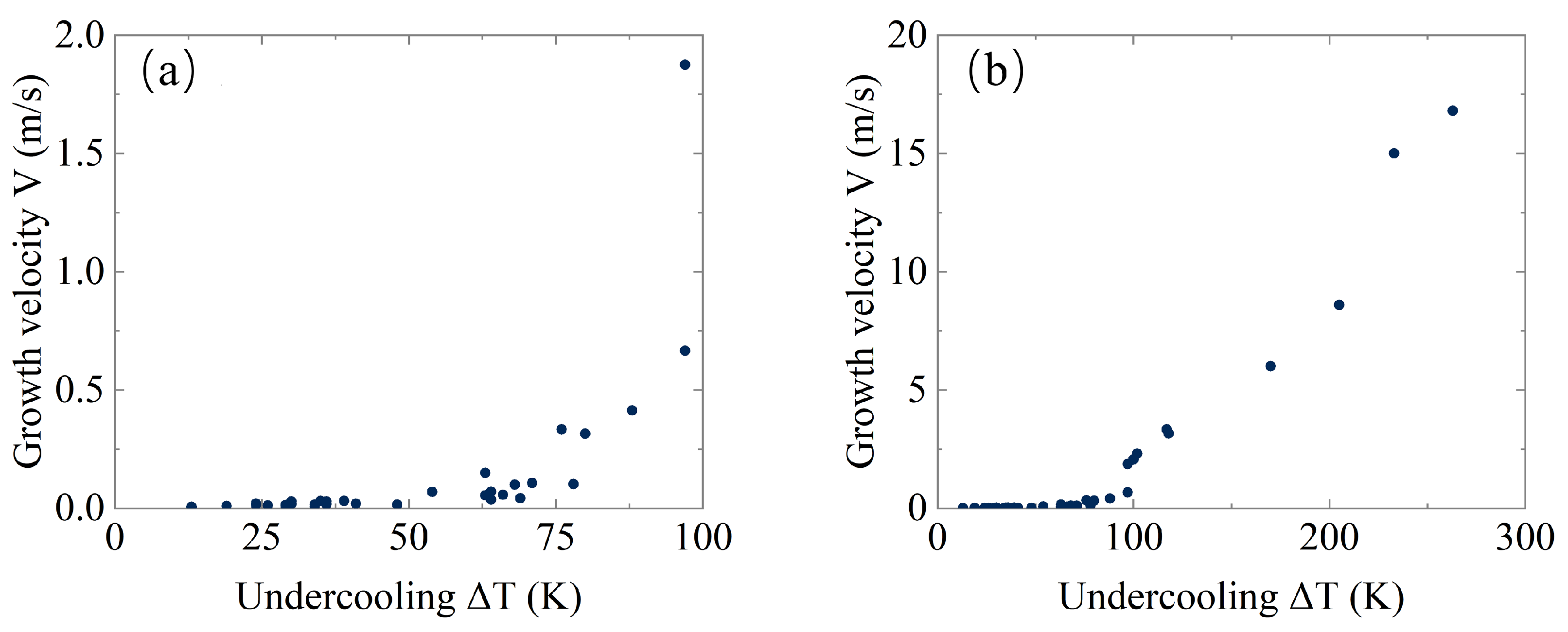
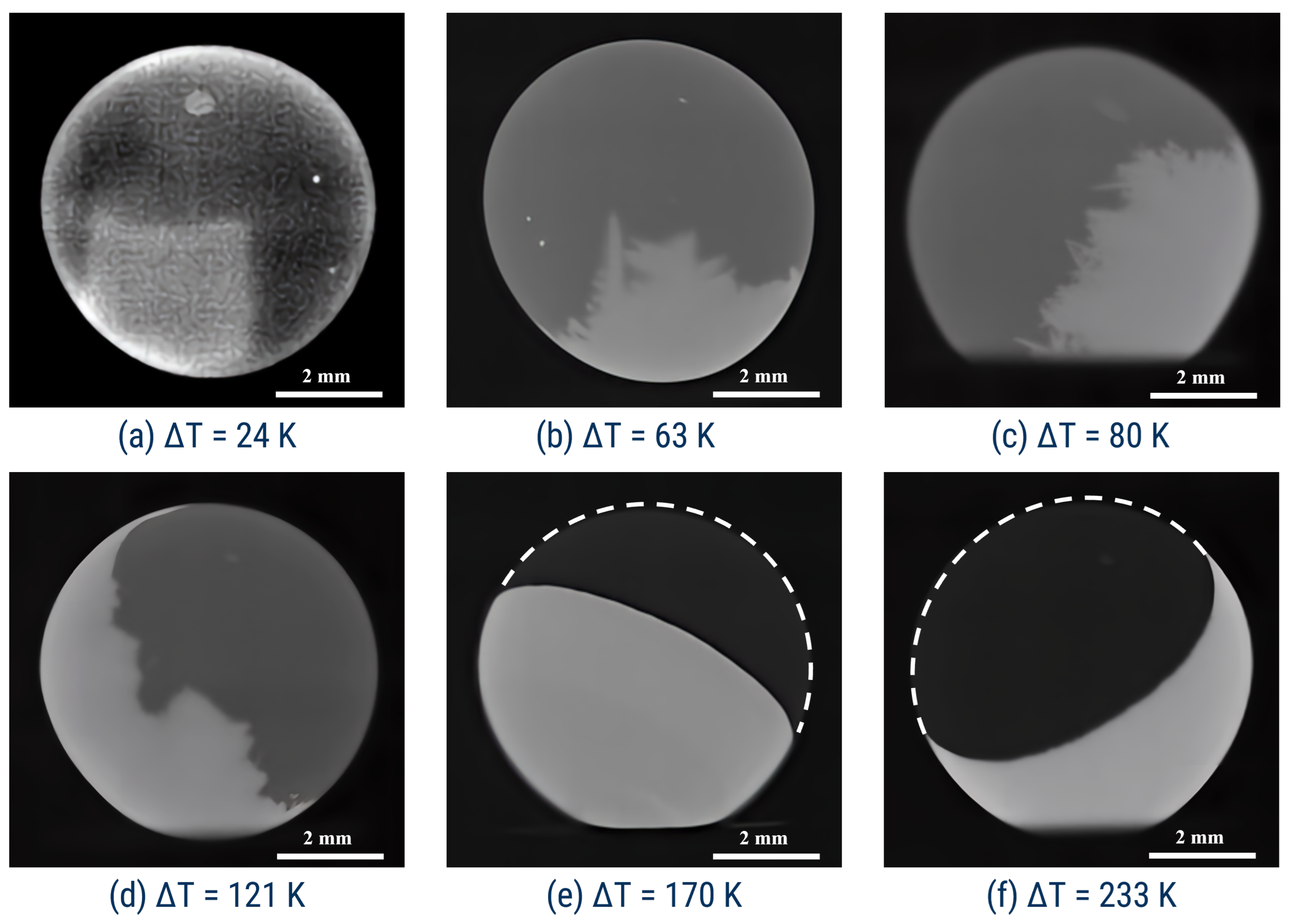
As shown in Figure 2, the interface growth velocity exhibits an exponential increase within the range of small and intermediate undercooling and the possible change to the linear law with the higher level of undercooling. Indeed, within the range of small and moderate values of undercooling, the interface velocity increases gradually; however, the velocity essentially rises at the higher undercooling approximately of Δ T = 160 K. Along with the variation of growth rate, the recalescence front is also changed from mesoscopically rough to smooth spherical/planar front (see transition in recalescence front in Figure 3a–f. Very probably, the cellular/dendritic microstructure dictated by short-range solute diffusion is changed in this case to the large dendrites growth which is governed by long-range thermal transport. Such kinetic crossover is accompanied by the velocity rising existing due to the nonequilibrium trapping of atoms (so/called “solute trapping effect”) in the alloy [16]. The solute trapping decreases the solutal atmosphere around the solid/liquid interface, respectively, decreasing the solute drag at the solid–liquid interface, and, as a result, it leads to the increase in the crystal growth velocity. This behavior is shown by calculations summarized in Appendix A and shown in Figure A1.

3.2. Microstructure Analysis

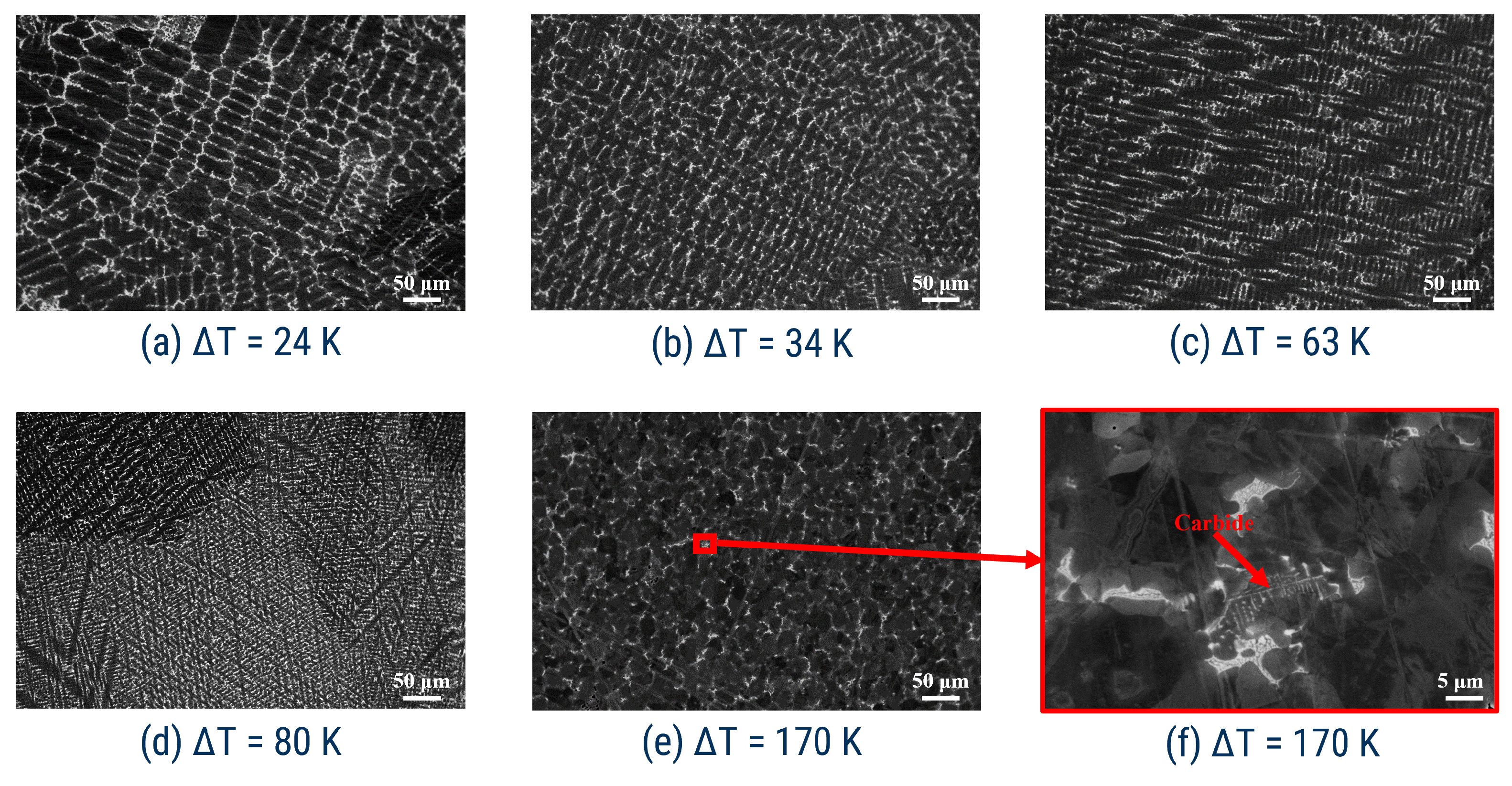
The SEM investigations showed that the samples that solidified at Δ T < 160 K have a dendritic microstructure. Figure 4 demonstrates the microstructure consisting of three microconstituents: periodic dark gray dendrite γ -matrix, halos of the precipitated γ -phase (both γ -and Laves phases in our samples are found; however, one can only mention them as γ due to the rough resolution to quantify exactly these phase), and light gray interdendritic region. Consistently with Figure 3, the microstructure becomes finer with the increase in undercooling in samples (see Figure 4a–c).
In addition to the typical dendritic structure, fine equiaxed grains (Figure 4e) were found in the sample solidified at Δ T = 170 K. At the boundaries among dendritic cells, precipitation phases of different shapes can be seen due to the segregation of the local chemical composition. The varying brightness of the dendritic cells in Figure 4e exists mainly due to the various crystal orientations. The relationship between the structure of undercooling liquid and nucleation is an issue of discussion in [19,20]. The correlative study carried out showed that solidified samples of IN718 show grain sizes on the order of micrometers, and they are very heterogeneous at the microscale. Our metallographic and electronic microscope studies show that the typical size of grains has the order on micrometers in samples of IN718 solidified at the undercooling of 10–80 K. When the undercooling of samples reaches 170 K, the structural region with equiaxed morphology is found. This region can be caused by the high cooling rate near the bottom of the sample [16]. According to the nucleation theory [19,20], the nucleation rate in the alloy melt increases with the rise of undercooling. Therefore, there are more nuclei formed in the highly undercooled alloy melt than in the less undercooled alloy melt. In addition, the strong recalescence under higher undercooling conditions can also remelt and break the dendrite arms due to their instability [21,22]. Finally, the cross-section with these small grains may represent crystalline cells in the direction perpendicular to the primary growth direction.

3.3. Dendrite Arm Spacing Analysis (Linear Intercept Method)

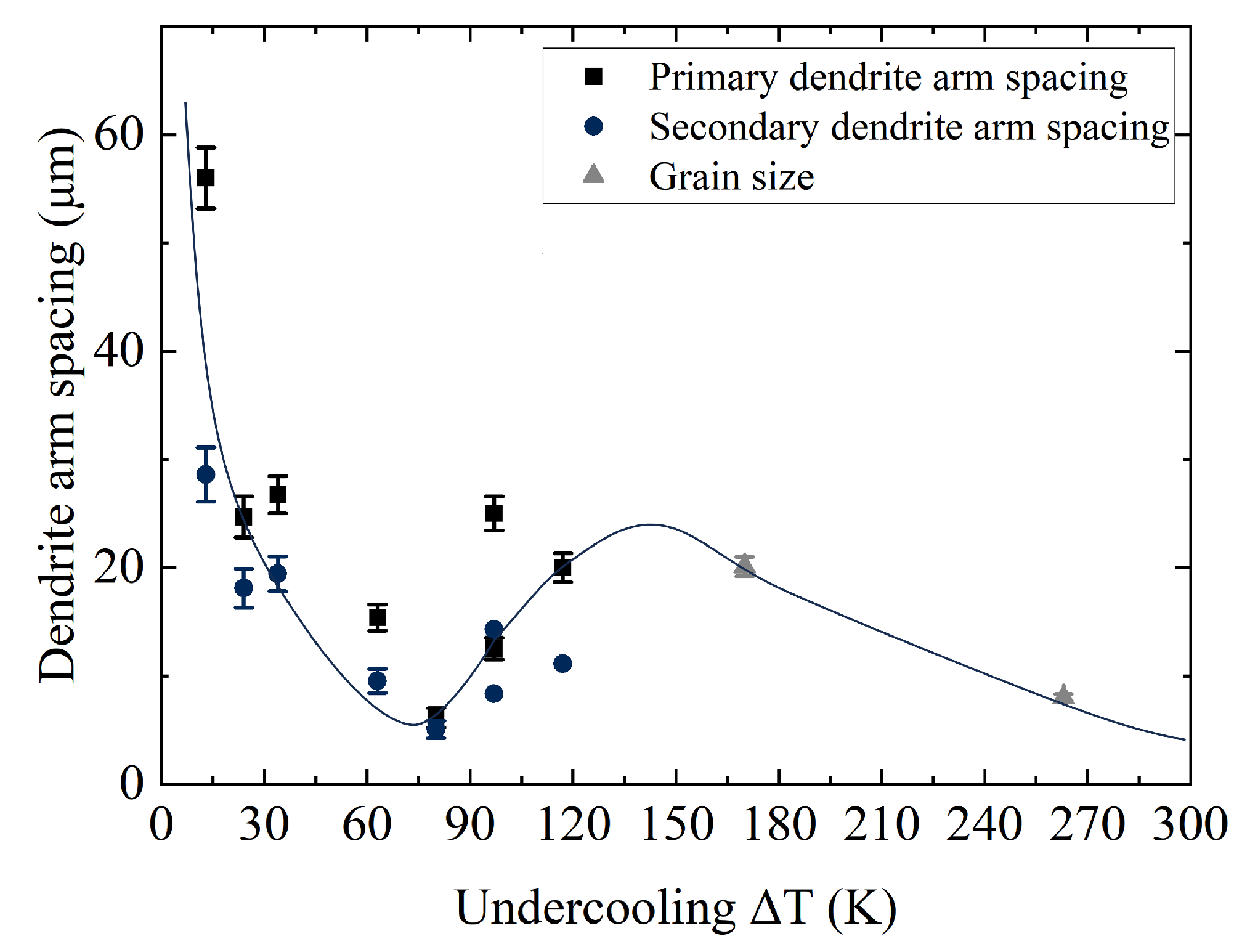
The primary dendrite arm spacing (PDAS) and secondary dendrite arm spacing (SDAS) can be utilized to evaluate the structure of samples solidified at different undercoolings. PDAS has a significant effect on the mechanical properties, but the secondary dendrite arm spacing has a direct effect on the segregation of components, the secondary phase precipitation, and the distribution of microscopic shrinkage defects. Moreover, the SDAS is responsible for the interdiffusion of alloy components and, respectively, for the homogenization of a sample. Using ImageJ software (version 1.53e), the line intercept method was applied to measure the primary and secondary dendrite spacings, following the procedure described in [23]. It can be seen from Figure 4 that the microstructure of samples solidified at different undercooling is composed of well-developed dendritic structures up to the undercooling Δ T = 80 K. The PDAS and SDAS are characterized by a decreasing trend in microstructure with the increase in undercooling. This is a well-known trend caused by the higher solidification rate and also the increasing thermal gradient [19]. During the rapid solidification process, a great number of crystal nuclei in the melt pool do not have enough time to grow and create grains. Furthermore, based on the theory introduced by Kirkwood [24], the spacing between secondary dendrite arms is proportional to the undercooling (Figure 5): at lower undercooling, one can find the bigger distance within the space of PDAS and SDAS. In the range of 63 K and 80 K, the characteristic space in PDAS and SDAS tends toward confluence. This means that the characteristic length of the dendrites decreases such that it becomes the order of distance between secondary arms. For the exceptional undercooling of 170 K, the grain size is not presented in Figure 5 because small-grained crystals were found in this highly undercooled sample.

3.4. Phase Fraction Using Scanning Electron Microscopy Image Analysis

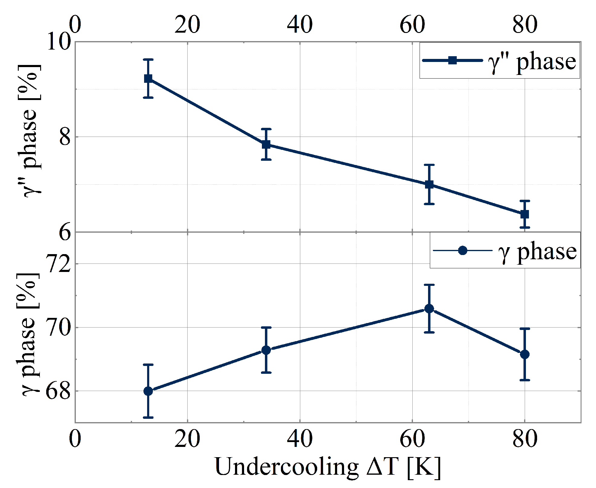
In this study, phase distribution in IN718 samples was characterized using scanning electron microscopy (SEM) under the backscattered electron (BSE) mode. The software MATLAB 8.0 was utilized for all BSE image processing. MATLAB open-site programs were developed to process grayscale photos with gray intensity values ranging from 0 to 255. Before background correction, the BSE pictures underwent preliminary processing, which includes histogram normalization and noise filtering. Once the background of the BSE image became homogeneous, a global threshold was applied to the entire grayscale image. If a pixel’s gray intensity was below the threshold, it was assigned the value 0 (black), while all other pixels were assigned the value 1 (white). The fraction of different phases was determined based on the grayscale differences among distinct phases. The results shown in Figure 6 indicate that the fraction of the primary γ -phase (primary dendrite region) presents a trend of increasing in the range of small undercoolings (13 K–63 K), for instance, the fraction reaches its summit at 63 K of 70.2% and shows a gradual decrease up to 68.9% at Δ T = 80 K. By contrast, fraction of the γ -phase shows a downward direction in this range of undercooling, in which the phase fraction changes from 9.2% to 6.3% at Δ T = 13–80 K.

3.5. Mechanical Properties

Several different methods to measure the mechanical properties are known to quantitatively estimate the elasticity, plasticity, hardness, and fragility of alloy samples. In the present work, microhardness by Vickers was measured to obtain averaged values of microhardness over the entire cross-section of the specimen.
Methodically, each sample was tested at room temperature statistically under the same conditions. Our measurements show that the Vickers hardness of the IN718 samples solidified with the undercooling between 13 K and 170 K is in a range from 211 HV 0.2 ± 10 to 244 HV 0.2 ± 17. Within this measurable range of microhardness, the nonlinear dependence on undercooling was found (see Figure 7). The obtained dependence shows a clear trend for microhardness increasing. The dispersion of dendritic structure with γ -phase increases (see Figure 6); therefore, microhardness increases with undercooling (Figure 7). These measurements are consistent with the downward branch of the dendrite arm spacing at Δ T < 85 K, i.e., within the diffusion-limited range of the dendrite growth. The only points at which dispersion decreases and microhardness increases are attributed to the sample solidified Δ T = 80 K. In our understanding, around this point, the transition from solute diffusion-limited growth to thermally controlled growth begins. Namely, around this point, the solute trapping starts with the formation of the metastable crystalline structure, which usually leads to improved material properties of alloys [13].
Because the presently measured microhardness gives only averaged values, which give information for every measurement value on several phases, the reason for the appearance of the nonlinearity of Figure 7 might be clarified after nanoindentation.

4. Conclusions

The solidification behavior of droplets and their growth front was investigated using an EML facility with observations recorded by IR pyrometer and a high-speed camera. The solidification kinetics were evaluated within the undercooling range of 13 K to 263 K. This temperature variation corresponds to dendritic growth velocities ranging from 6 · 10 3 m/s to 16.8 m/s.
In the range of the diffusion-limited growth within which the dispersion of dendrites increases (the dendrite arm spacing decreases), the increase in microhardness was obtained. At the very beginning of the transition to thermally controlled growth, the dispersion decreases (the dendrite arm spacing increases) but the microhardness is still increased. This tendency exists due to the beginning of solute trapping and formation of the metastable phase, exhibiting the improved hardness of samples at higher undercooling.
The transformation of the microstructure in IN718 alloy, shifting from dendrite to grain, and the decreasing of the dendrite arm spacing were discussed with respect to the increasing undercooling. It was found that
-
The sharp change in the shape of the recalescence front exists at Δ T = 170 K;
-
The crystalline microstructure changes at Δ T = 170 K;
-
The characteristic dendritic arm spacings change by the novel exponential law at Δ T > 170 K.
These drastic changes are the result of the transition from solute diffusion-limited to thermally controlled growth predicted by the experimental measurements of the dendrite growth velocity and confirmed by the predictions of the theoretical model. The transition to pure thermally controlled growth is sharp and it occurs at the dendrite growth velocity equal to the speed of solutes diffusion in bulk liquid.

Author Contributions

Conceptualization, Y.F., N.K., M.S., S.L. and P.K.G.; methodology, Y.F., N.K., M.S., S.L. and P.K.G.; software, Y.F., C.Y., N.K. and P.K.G.; validation, Y.F., C.Y., M.S., K.F., S.L. and P.K.G.; formal analysis, Y.F., C.Y., M.S., K.F., M.K., S.L. and P.K.G.; investigation, Y.F., C.Y., M.S., K.F., M.K., S.L. and P.K.G.; resources, Y.F., C.Y., M.S., K.F., M.K., S.L. and P.K.G.; data curation, Y.F., C.Y., M.S., K.F. and P.K.G.; writing—original draft preparation, Y.F. and P.K.G.; writing—review and editing, Y.F., C.Y., N.K., M.S., K.F., M.K., S.L. and P.K.G.; visualization, Y.F. and C.Y.; supervision, S.L. and P.K.G.; project administration, S.L. and P.K.G.; funding acquisition, P.K.G. and S.L. All authors have read and agreed to the published version of the manuscript.

Funding

This research was funded by the German Science Foundation (DFG-Deutsche Forschungsgemeinschaft) under the Project GA 1142/11-1.

Data Availability Statement

Data are available on request.

Acknowledgments

Authors thank Jianrong Gao for useful exchanges.

Conflicts of Interest

The authors declare no conflicts of interest. The authors have no known competing financial interests or personal relationships that could have appeared to influence the work reported in this paper.

Abbreviations

The following abbreviations are used in this manuscript:
IN718Inconel 718
EMLElectromagnetic levitation
S/LSolid–liquid
TLAThree letter acronym
SEMScanning electron microscopy
BSEBackscattered electron
PDASPrimary dendrite arm spacing
SDASSecondary dendrite arm spacing
EBSDElectron backscattering diffraction
EDSEnergy-dispersive X-ray spectrometer

Appendix A. Sharp Interface Model and Predictions of Crystal Growth Kinetics

Equations of the sharp interface model [25] combine a selection criterion of stable dendrite mode and the balance of undercooling contributions at the dendritic tip by taking into account the local nonequilibrium at the interface and in bulk liquid. The total undercooling
Δ T T L 0 T 0 = T m + m e N b c 0 N b + m e C r c 0 C r T 0 ,
represents the temperature balance at the dendrite tip as
Δ T = Δ T T + Δ T C + Δ T N + Δ T R + Δ T K ,
where c 0 N b and c 0 C r are the nominal concentrations of N b and C r , respectively, m e N b and m e C r are the liquidus line slopes in the equilibrium phase quasi-binary diagrams of N i N b and N i C r , respectively, T 0 is the far-field temperature of the liquid, and T m is melting temperature of nickel. The extension to three-component alloy on the basis of definitions (A1) and (A2) was also made for N i Z r A l alloy [26].
The total undercooling (A2) is determined as a sum of thermal contribution Δ T T , constitutional undercooling Δ T C caused by solute redistribution at the solid–liquid interface, the shift Δ T N of the liquidus line from its equilibrium position in the kinetic phase diagram of steady-state solidification undercooling Δ T R due to the interface curvature (Gibbs–Thomson effect), and the kinetic undercooling Δ T K that determines the intensity of atomic kinetics on the dendritic tip. The concrete definitions of the undercooling contributions are given in our previous works, for instance, in Ref. [25].
Because Equation (A2) is the only equation for two variables, the velocity V and radius R of the dendrite tip, at the given (and experimentally measurable) undercooling Δ T , a second equation is provided by the following stability condition [25]:
R = 1 σ · d 0 Δ 0 T Q P T ξ T 2 Δ v P C ξ C , V < V D ; 1 σ · d 0 Δ 0 T Q P T ξ T , V V D .
The condition (A3) follows from the expression σ * 2 d 0 D T / ( R 2 V ) = σ [ f T ( P T ) ξ T ( P T ) + f C ( P C ) ξ C ( P C , V / V D ) ] , which describes the stable mode of the dendritic tip growth due to anisotropy ε c of the interfacial energy, and the stability parameter is proportional to the anisotropy as σ ε c 7 / 4 [27,28,29,30]. The thermal stability function in rapid solidification is given by
ξ T ( P T ) = [ 1 + b 1 15 ε c P T 1 + b 0 D T β / d 0 ] 2 ,
where b 0 and b 1 are the asymptotic coefficients of joiningof large thermal Péclet numbers regime and growth kinetics regime, respectively, and β = 1 / ( μ k T Q ) is the kinetic growth parameter. The chemical stability function at rapid solidification is described by
ξ C ( P C , V / V D ) = 1 + b 2 15 ε c P C * ( 1 + b 0 D L β / d 0 CD ) 2 , V < V D ; 0 , V V D ,
where b 2 is the asymptotic coefficient of joiningof large thermal Péclet numbers regime, d 0 C D is the chemical capillary length, and P C * = P C / 1 V 2 / V D 2 .
The limit V D describes the regime of Fickean diffusion under the local thermodynamic equilibrium in bulk phases. Applying this limit to the stability growth mode by Equations (A2)–(A5) predicts the criterion formulated by Trivedi and Kurz [31] developed for rapid dendritic growth [32]. Within the limit of small Peclét numbers, P T 1 and P C * 1 , and with the local equilibrium limits V D I and V D , Equations (A3)–(A5) transform to previously obtained conditions of Ben Amar and Pelcé [28]. The selection criterion (A3) is written for the four-fold symmetry of crystal lattices that can be generalized to other crystalline symmetries [33,34].
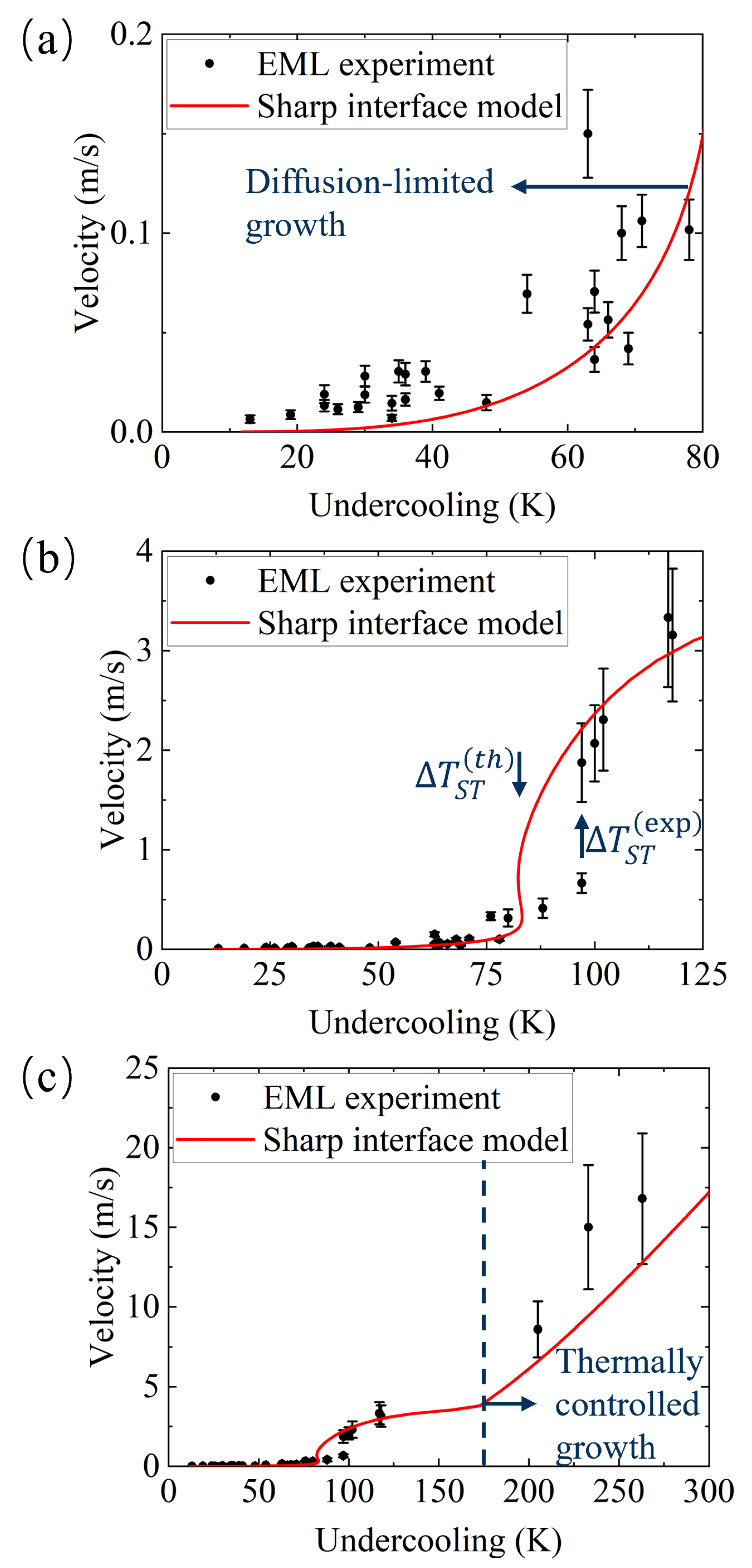
Figure A1 demonstrates results of computations using the sharp interface model (A1)–(A5) and the material parameters of IN718 in the ternary alloy approximation (to adjust our calculations to experimental data in dendrite growth kinetics (Figure A1), the special material parameters were shifted a bit in comparison with the previous data on quasi-binary approximation of INCONEL 718. The change in solute partitioning coefficient and liquidus line slope for N i N b is consistent with the change of parameters for the N i N b alloy modeled in quasi-binary approximation for Inconel [15]) summarized in Table A1. The N i C r N b ternary approximation of IN718 was chosen since N b is a key alloying element in this alloy for precipitation hardening. It forms carbides and contributes to the formation of γ -phase N i 3 N b , strengthening the alloy through precipitation hardening mechanisms. The chromium is a solid-solution strengthener in nickel-based alloys such as the IN718 alloy. It forms a solid solution with the nickel matrix, contributing to the alloy’s strength and hardness. Also, C r contributes to the formation of Laves-phase ( N i , F e , C r ) 2 ( N b , M o , T i ) . As is known, the formation of long-chain Laves phase promotes initiation and propagation of cracks [35]. With the movement of the solidification front, the solutes are accumulated at the interface, and most of them are partitioned to the residual liquid phase enriching the area between the dendrites. It is a possible mode of carbides and Laves-phase precipitation [36]. To investigate the influence of solutes with partitioning coefficient smaller than 1 ( k e < 1 exhibits solute element N b in the solvent N i ) and larger than 1 ( k e > 1 exhibits solute element C r in the solvent N i ), the sharp interface model for the ternary N i C r N b system is developed and used in the Appendix A of the present paper. Computations are shown for three different ranges of undercooling:
-
Theoretically well-described region of small values of undercooling in which the dendrite growth proceeds in the solute diffusion-limited mode (Figure A1a); some discrepancy between theoretical curve and experimental data might be attributed to the ternary approximation in solidification analysis of the multicomponent IN718 alloy.
-
Theoretical description of the transition from solute diffusion-limited to thermally controlled growth with a small shift of the model prediction, with relatively experimental data for its beginning; see the difference in undercooling between Δ T S T ( t h ) and Δ T S T ( e x p ) in Figure A1b.
-
The whole range of undercooling, including the sharp change to the purely thermally controlled growth at V = V D = 3.7 (m/s) (Figure A1c).
Table A1. Sharp interface model parameters for IN718 in the N i N b C r ternary alloy approximation.
ParameterSharp Interface ModelRefs.
Niobium concentration, c 0 N b 5 wt%pw
Chromium concentration, c 0 C r 18 wt%pw
Niobium partition coefficient *, k e N b 0.38 pw
Chromium partition coefficient *, k e C r 1.12 pw
Equilibrium liquidus slope of Ni-Nb, m e N b 10.51 K/wt%[37]
Equilibrium liquidus slope of Ni-Cr, m e C r 10.156 K/wt%[37]
Melting point, T m 1726 Kpw
Gibbs–Thomson coefficient, Γ 1.55 · 10 7 K·m[38]
Adiabatic temperature of solidification, T Q 259.72 Kpw
Nb diffusion coefficient, D L N b 9 · 10 9 m2/s[39]
Cr diffusion coefficient, D L C r 1.523 · 10 8 m2/s[39]
Thermal diffusivity, a L 7.19 · 10 6 m2/s[39]
Kinetic growth coefficient, μ K 0.15 m/s/Kpw
Capillary anisotropy strength, ϵ c 0.02 pw
Bulk diffusion speed, V D 3.7 m/spw
Diffusion speed of Nb at the interface, V D I N b 0.5 m/spw
Diffusion speed of Cr at the interface, V D I N b 0.15 m/spw
Stability constant, σ 0 0.0085 pw
* pw—present work.
As is seen from Figure A1, the three different regimes, which are characterized by different values of length scales, are described using the only theoretical model. Using the three-component ( N i N b C r ) approximation for IN718 (consisting of eight chemical components in reality; Table 1) might be satisfactorily described by Equations (A1)–(A5). Especially, the transition to the pure thermally controlled growth is predicted by the experimental measurements of the dendrite growth velocity as the sharp transition (see Figure A1c), consistently with
-
The sharp change in the shape of recalescence front that is fixed at Δ T = 170 K (see Figure 3b–c);
-
Drastic change in the crystalline microstructure fixed at Δ T = 170 K (see Figure 4b–c);
-
Novel exponential behavior of the dendrite arm spacing fixed at Δ T > 170 K (see Figure 5).
We especially note that the jump in dendrite tip velocity V shown in Figure A1b and Figure 2 around Δ T = 100 K is explained by the experimentally measured step around the minimal value of the dendrite tip radius R at the very ending of the solute diffusion-limited growth and at the beginning of the transition to thermally-controlled growth. At this point, R is going through the minimum and may take smaller/bigger values in the free dendrite solidification, leading to the appearance of the step for V-data. Indeed, as it follows from values for dendrite arm spacing, which are directly correlated with R (see Figure 5), the transition of “bigger–smaller–bigger” V-values occurs in the range of the undercooling 75 < Δ T (K) < 110 .
Figure A1. Dendrite growth velocity V as a function of undercooling Δ T for IN718 alloy. The experimental data are represented by the symbols, and the lines give the predictions of the sharp interface model given by Equations (A1)–(A5): (a) for region of relatively small undercooling; (b) for small and intermediate undercooling; and (c) in the whole range of undercooling. “The First Frame–Last Frame method” (FF–LF method) was used to estimate the growth velocity [40]. In this method, the time from the first frame and the time for the last frame of the digital movie from the high-speed camera recording are taken for the period of the primary phase growth in covering the entire sample by the recalescence front. The error bars in the data were determined by 1 / t o t a l n u m b e r o f f r a m e s from the recorded digital movie of the high-speed camera.
Crystals 14 00244 g0a1
The transition to the pure thermally controlled growth is sharp and it occurs at the characteristic velocity (the bulk diffusion speed V D is the characteristic speed for the diffusion front propagation [41,42]. This speed describes the maximum speed for solute diffusion and characterizes the beginning of the diffusionless solidification with the transition to the thermally controlled growth) V = V D = 3.7 (m/s) (Figure A1c), which is 5 7 times smaller than the same transition obtained experimentally and described theoretically for substitution or interstitial binary alloys [25]. Such a big difference in the bulk diffusion speed V D in the multicomponent and binary alloys can directly indicate the essential deceleration of the diffusion processes in the complex and chemically multicomponent alloy with possible atomic interactions among them. Furthermore, even with the averaging of the bulk diffusion speed in multicomponent IN718 alloy, we are able to predict the sharp ending of the transition to pure thermally controlled growth of dendrites around the initial undercooling Δ T = 170 K (see Figure A1c) that generally follows from the theory of rapid solidification (see Ref. [25] and references therein). The transition to pure thermally controlled growth leads to the growth of big thermal dendritic patterns with a characteristic scale comparable with the size of droplets, which are represented by the smooth recalescense front (see Figure 3).

References

  1. Reed, R.C. The Superalloys: Fundamentals and Applications; Cambridge University Press: Cambridge, MA, USA, 2006. [Google Scholar] [CrossRef]
  2. Rezayat, M.; Aboutorabi Sani, A.; Talafi Noghani, M.; Saghafi Yazdi, M.; Taheri, M.; Moghanian, A.; Mohammadi, M.A.; Moradi, M.; Mateo García, A.M.; Besharatloo, H. Effect of Lateral Laser-Cladding Process on the Corrosion Performance of Inconel 625. Metals 2023, 13, 367. [Google Scholar] [CrossRef]
  3. Medeiros, S.; Prasad, Y.; Frazier, W.G.; Srinivasan, R. Modeling grain size during hot deformation of IN 718. Scr. Mater. 1999, 42, 17–23. [Google Scholar] [CrossRef]
  4. Li, R.; Yao, M.; Liu, W.; He, X. Isolation and determination for delta, γ and γ′′ phases in Inconel 718 alloy. Scr. Mater. 2002, 46, 635–638. [Google Scholar] [CrossRef]
  5. Miller, M.; Babu, S.; Burke, M. Intragranular precipitation in alloy 718. Mater. Sci. Eng. A 1999, 270, 14–18. [Google Scholar] [CrossRef]
  6. Hong, S.; Chen, W.; Wang, T. A diffraction study of the γ′′ phase in INCONEL 718 superalloy. Metall. Mater. Trans. A 2001, 32, 1887–1901. [Google Scholar] [CrossRef]
  7. Sencer, B.; Bond, G.; Garner, F.; Hamilton, M.; Maloy, S.A.; Sommer, W. Correlation of radiation-induced changes in mechanical properties and microstructural development of Alloy 718 irradiated with mixed spectra of high-energy protons and spallation neutrons. J. Nucl. Mater. 2001, 296, 145–154. [Google Scholar] [CrossRef]
  8. Zhang, W.; Liu, F.; Liu, F.; Huang, C.; Liu, L.; Zheng, Y.; Lin, X. Effect of Al content on microstructure and microhardness of Inconel 718 superalloy fabricated by laser additive manufacturing. J. Mater. Res. Technol. 2022, 16, 1832–1845. [Google Scholar] [CrossRef]
  9. Fleck, M.; Querfurth, F.; Glatzel, U. Phase field modeling of solidification in multi-component alloys with a case study on the Inconel 718 alloy. J. Mater. Res. 2017, 32, 4605–4615. [Google Scholar] [CrossRef]
  10. Rahul, M.; Agilan, M.; Mohan, D.; Phanikumar, G. Integrated experimental and simulation approach to establish the effect of elemental segregation in Inconel 718 welds. Materialia 2022, 26, 101593. [Google Scholar] [CrossRef]
  11. Antonsson, T.; Fredriksson, H. The effect of cooling rate on the solidification of INCONEL 718. Metall. Mater. Trans. B 2005, 36, 85–96. [Google Scholar] [CrossRef]
  12. Knorovsky, G.A.; Cieslak, M.J.; Headley, T.J.; Romig, A.D.; Hammetter, W.F. INCONEL 718: A solidification diagram. Metall. Trans. A 1989, 20, 2149–2158. [Google Scholar] [CrossRef]
  13. Herlach, D.M.; Galenko, P.K.; Holland-Moritz, D. Metastable Solids from Undercooled Melts; Elsevier: Amsterdam, The Netherlands, 2007. [Google Scholar]
  14. Kropotin, N.; Fang, Y.; Yu, C.; Seyring, M.; Freiberg, K.; Lippmann, S.; Pinomaa, T.; Laukkanen, A.; Provatas, N.; Galenko, P.K. Modelling of the Solidifying Microstructure of Inconel 718: Quasi-Binary Approximation. Modelling 2023, 4, 323–335. [Google Scholar] [CrossRef]
  15. Elahi, S.; Tavakoli, R.; Boukellal, A.; Isensee, T.; Romero, I.; Tourret, D. Multiscale simulation of powder-bed fusion processing of metallic alloys. Comput. Mater. Sci. 2022, 209, 111383. [Google Scholar] [CrossRef]
  16. Herlach, D.; Eckler, K.; Karma, A.; Schwarz, M. Grain refinement through fragmentation of dendrites in undercooled melts. Mater. Sci. Eng. A 2001, 304, 20–25. [Google Scholar] [CrossRef]
  17. Toropova, L.V.; Alexandrov, D.V.; Kao, A.; Rettenmayr, M.; Galenko, P.K. Electromagnetic levitation method as a containerless experimental technique. Phys. Uspekhi 2023, 66, 722–733. [Google Scholar] [CrossRef]
  18. Publication Number SMC-045. Copyright© Special Metals Corporation. 2007. Available online: http://www.specialmetals.com (accessed on 1 December 2023).
  19. Kurz, W.; Fisher, D.; Rappaz, M. Fundamentals of Solidification, 5th ed.; Trans Tech Publications Ltd.: Zurich, Switzerland, 2023. [Google Scholar]
  20. Boettinger, W.J.; Coriell, S.R.; Greer, A.; Karma, A.; Kurz, W.; Rappaz, M.; Trivedi, R. Solidification microstructures: Recent developments, future directions. Acta Mater. 2000, 48, 43–70. [Google Scholar] [CrossRef]
  21. Schwarz, M.; Karma, A.; Eckler, K.; Herlach, D.M. Physical Mechanism of Grain Refinement in Solidification of Undercooled Melts. Phys. Rev. Lett. 1994, 73, 1380–1383. [Google Scholar] [CrossRef]
  22. Karma, A. Model of grain refinement in solidification of undercooled melts. Int. J. Non-Equilib. Process. 1998, 11, 201–233. [Google Scholar]
  23. Vandersluis, E.; Ravindran, C.R. Comparison of Measurement Methods for Secondary Dendrite Arm Spacing. Metallogr. Microstruct. Anal. 2017, 6, 89–94. [Google Scholar] [CrossRef]
  24. Kirkwood, D.H. A simple model for dendrite arm coarsening during solidification. Mater. Sci. Eng. 1985, 73, L1–L4. [Google Scholar] [CrossRef]
  25. Galenko, P.K.; Jou, D. Rapid solidification as non-ergodic phenomenon. Phys. Rep. 2019, 818, 1–70. [Google Scholar] [CrossRef]
  26. Galenko, P.K.; Reutzel, S.; Herlach, D.M.; Fries, S.G.; Steinbach, I.; Apel, M. Dendritic solidification in undercooled Ni–Zr–Al melts: Experiments and modeling. Acta Mater. 2009, 57, 6166–6175. [Google Scholar] [CrossRef]
  27. Barbieri, A.; Langer, J.S. Predictions of dendritic growth rates in the linearized solvability theory. Phys. Rev. A 1989, 39, 5314–5325. [Google Scholar] [CrossRef]
  28. Ben Amar, M.; Pelcé, P. Impurity effect on dendritic growth. Phys. Rev. A 1989, 39, 4263–4269. [Google Scholar] [CrossRef]
  29. Brener, E.A.; Mel’nikov, V.I. Two-dimensional dendritic growth at arbitrary Peclet number. J. Phys. 1990, 51, 157–166. [Google Scholar] [CrossRef]
  30. Müller-Krumbhaar, H.; Abel, T.; Brener, E.; Hartmann, M.; Eissfeldt, N.; Temkin, D. Growth-Morphologies in Solidification and Hydrodynamics. JSME Int. J. Ser. B Fluids Therm. Eng. 2002, 45, 129–132. [Google Scholar] [CrossRef]
  31. Trivedi, R.; Kurz, W. Morphological stability of a planar interface under rapid solidification conditions. Acta Metall. 1986, 34, 1663–1670. [Google Scholar] [CrossRef]
  32. Trivedi, R.; Kurz, W. Dendritic growth. Int. Mater. Rev. 1994, 39, 49–74. [Google Scholar] [CrossRef]
  33. Alexandrov, D.V.; Galenko, P.K. Selected mode of dendritic growth with n-fold symmetry in the presence of a forced flow. EPL Europhys. Lett. 2017, 119, 16001. [Google Scholar] [CrossRef]
  34. Alexandrov, D.V.; Galenko, P.K.; Toropova, L.V. Thermo-solutal and kinetic modes of stable dendritic growth with different symmetries of crystalline anisotropy in the presence of convection. Philos. Trans. R. Soc. A Math. Phys. Eng. Sci. 2018, 376, 20170215. [Google Scholar] [CrossRef] [PubMed]
  35. Yuan, K.; Guo, W.; Li, P.; Wang, J.; Su, Y.; Lin, X.; Li, Y. Influence of process parameters and heat treatments on the microstructures and dynamic mechanical behaviors of Inconel 718 superalloy manufactured by laser metal deposition. Mater. Sci. Eng. A 2018, 721, 215–225. [Google Scholar] [CrossRef]
  36. Chen, M.; Du, Q.; Shi, R.; Fu, H.; Liu, Z.; Xie, J. Phase field simulation of microstructure evolution and process optimization during homogenization of additively manufactured Inconel 718 alloy. Front. Mater. 2022, 9, 1043249. [Google Scholar] [CrossRef]
  37. Nie, P.; Ojo, O.; Li, Z. Numerical modeling of microstructure evolution during laser additive manufacturing of a nickel-based superalloy. Acta Mater. 2014, 77, 85–95. [Google Scholar] [CrossRef]
  38. Ferreira, D.; Bezerra, B.; Collyer, M.; Garcia, A.; Ferreira, I.L. The use of computational thermodynamics for the determination of surface tension and Gibbs–Thomson coefficient of multicomponent alloys. Contin. Mech. Thermodyn. 2018, 30, 1145–1154. [Google Scholar] [CrossRef]
  39. Connétable, D.; Ter-Ovanessian, B.; Andrieu, É. Diffusion and segregation of niobium in fcc-nickel. J. Phys. Condens. Matter 2012, 24, 095010. [Google Scholar] [CrossRef]
  40. Galenko, P.; Hanke, R.; Paul, P.; Koch, S.; Rettenmayr, M.; Gegner, J.; Herlach, D.; Dreier, W.; Kharanzhevski, E. Solidification kinetics of CuZr alloy: Ground-based and microgravity experiments. IOP Conf. Ser. Mater. Sci. Eng. 2017, 192, 012028. [Google Scholar] [CrossRef]
  41. Jou, D.; Casas-Vazquez, J.; Lebon, G. Extended Irreversible Thermodynamics, 4th ed.; Springer: Dordrecht, The Netherlands, 2010. [Google Scholar]
  42. Lebon, G.; Jou, D.; Casas-Vazquez, J. Understanding Non-Equilibrium Thermodynamics; Springer: Berlin/Heidelberg, Germany, 2008. [Google Scholar]
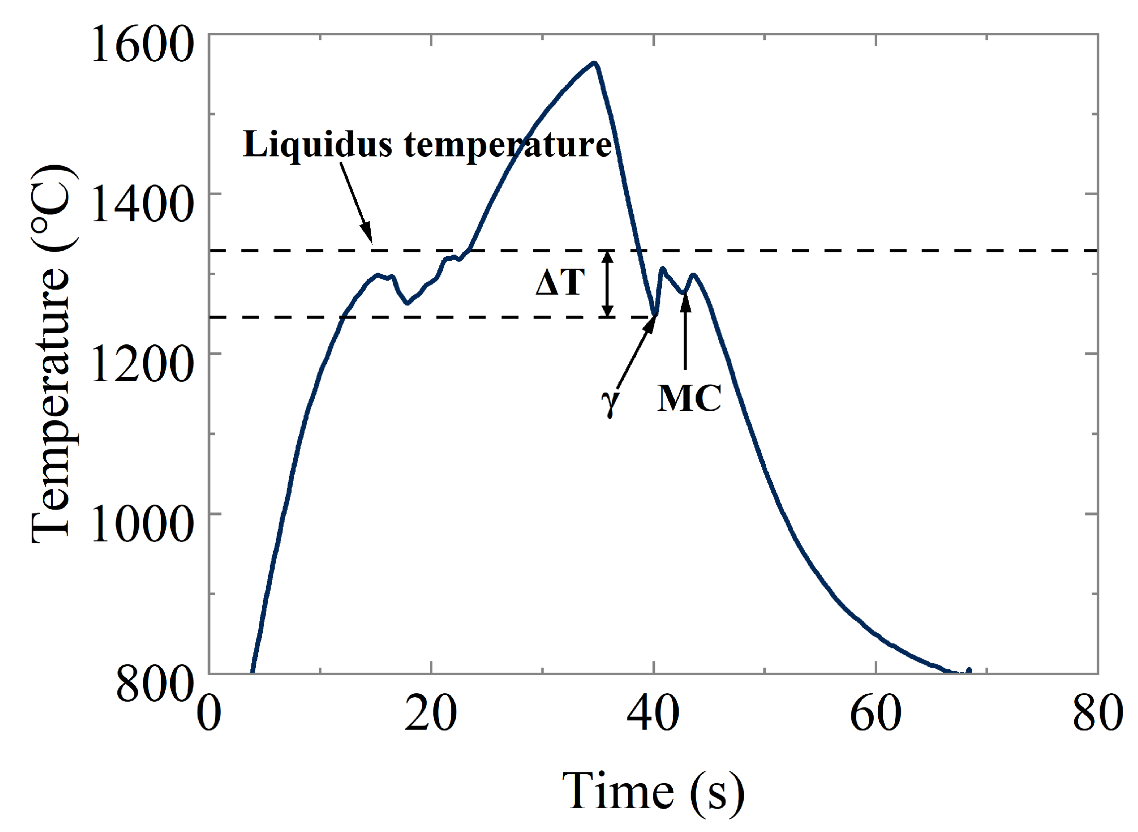
Figure 1. Illustration of temperature–time profiles of the samples during EML experiment. The undercooling Δ T is consistent with the nucleation and growth of the γ -phase as the primary dendritic-grained structure. The undercooling consistent with M C might be related to origination of carbides. Note that the temperature of the samples is well below the liquidus temperature at the end of first recalescence, because, in many experiments with containerless samples, the temperature upon first recalescence does not reach, and may be far from, liquidus temperature due to the ending of primary solidification in which dendrites with the residual interdendritic liquid phase filled the bulk droplet. In this case, the latent heat is not intensively released and the cooling gas around the droplet makes the further temperature increase impossible.
Crystals 14 00244 g001
Figure 2. Measured growth velocity V versus undercooling Δ T . The growth velocity represents the experimental measurement of the recalescence front propagation, which is the envelope of dendritic tips where the latent heat is intensively released. The dendrite velocity is shown at the small undercooling (a) and in the whole range of the measured velocity and undercooling (b).
Crystals 14 00244 g002
Figure 3. Recalescence front (envelope of growing dendritic tips). One can see different shapes of recalescence front between undercooled liquid (dark part of the droplet) and primary crystalline γ -phase (bright part of the droplet): (a) cellular–dendritic front in the mode of the atomistically diffusion-limited growth of crystals; (bd) dendritic front which becomes smoother with the increase in undercooling, i.e., with the increasing tendency to have a transition from solute-diffusion mode to thermal regime of the crystal growth; (e,f) planar front at the stage of pure thermal growth. The dashed semi-spherical curve in (e,f) shows the hidden boundary of the droplet.
Crystals 14 00244 g003
Figure 4. Backscattered SEM micrographs of the samples processed by EML with the corresponding growth interface morphology. The bright phase is the precipitation phase and the dark gray phase is the primary dendrite: (a) Δ T = 24 K, (b) Δ T = 34 K, (c) Δ T = 63 K, (d) Δ T = 80 K, (e) Δ T = 170 K; (f) carbides upon solidification at Δ T = 170 K. The transition from dendritic to small granular microstructure shown here is from the undercooling range 24 Δ T (K) 80 to the highest undercooling Δ T 170 K. The carbides were formed within interdendritic space that is shown in (f) by fragment of the grain’s boundary.
Crystals 14 00244 g004
Figure 5. Measurements of primary and secondary dendrite arm spacings using intercept method (100 measurements for each error bar). Measurements were made for IN718 samples (droplets) processed in EML and solidified at the different undercoolings. The curve shows the qualitative behavior of the dendrite (primary and secondary) arm spacing. This behavior is completely consistent with the growth of dendrites in the solute diffusion-limited mode ( Δ T < 80 K), thermally controlled regime of dendrite growth ( Δ T > 160 K), and within the range of the transitive mode ( 80 < Δ T ( K ) < 160 ) from solute diffusion to thermally controlled regime. For details, see the overview in [25].
Crystals 14 00244 g005
Figure 6. Analysis results of phase fraction for IN718 samples with undercoolings of 13 K, 34 K, 63 K, and 80 K. Note that the beginning of the decrease in the γ -phase fraction (primary dendrites) begins to decrease precisely in the range of undercooling Δ T = 60 80 K. As follows from Figure 5, this range is associated with the change of the primary dendritic arm spacing from its minimum value to the beginning of an increase in this dendritic spacing. It is quite possible that part of the sample crystallized at Δ T = 80 K, in which γ -phase measurements were made, and already shows an increase in the dendritic arm spacing, a decrease in the dendritic dispersity, and, as a consequence, a decrease in the dendritic phase fraction from the sample crystallized at Δ T = 63 K to a sample crystallized at Δ T = 80 K.
Crystals 14 00244 g006
Figure 7. Microhardness by Vickers in IN718 samples solidified at different values of undercooling.
Crystals 14 00244 g007
Table 1. Initial composition of IN718 [18] in wt.%.
ElementNiCrNbMoTiAlCFe
Measured concentration52.7818.74.953.041.010.550.046Balance
Powder concentration541882000Balance
Disclaimer/Publisher’s Note: The statements, opinions and data contained in all publications are solely those of the individual author(s) and contributor(s) and not of MDPI and/or the editor(s). MDPI and/or the editor(s) disclaim responsibility for any injury to people or property resulting from any ideas, methods, instructions or products referred to in the content.